The document describes the design of an automated guided vehicle (AGV) that can avoid collisions with obstacles. The AGV uses infrared LEDs and receivers connected to a microcontroller to detect obstacles on its path and signals the motors to change direction accordingly. Key components include a chassis, motors, a microcontroller, motor driver, power supply and infrared sensors. The microcontroller is programmed using AVR Studio to control the motor directions based on input from the infrared sensors to navigate around any obstacles.
A collision prevention warning system is an automobile safety system which enables vehicles to identify the chances of collision and give visual and audio warning to the driver so that the driver can take necessary action to avoid `a collision.
In this project we will be controlling the speed of Dc motor using Arduino controller. Dc motor is drive by using PWM technique and then using encoder to sense the rpm of DC motor. Encoder produces pulses in the output, which is feed into Arduino and Arduino controls the speed of DC motor. So we have implemented the feedback system which controls the speed of DC motor.
Arduino Workshop Day 2 - Advance Arduino & DIYVishnu
Arduino Workshop Day 2 - IR, Ultrasonic & Temperature - Humidity Sensor Interfacing & Do It Yourself - Line Follower, Light Follower & Obstacle Avoider.
Edgefxkits.com has a wide range of electronic projects ideas that are primarily helpful for ECE, EEE and EIE students and the ideas can be applied for real life purposes as well.
http://www.edgefxkits.com/
Visit our page to get more ideas on popular electronic projects developed by professionals.
Edgefx provides free verified electronic projects kits around the world with abstracts, circuit diagrams, and free electronic software. We provide guidance manual for Do It Yourself Kits (DIY) with the modules at best price along with free shipping.
This was my final year project based on embedded system
this is the code
http://downloads..com/download/24001476/code.rar.html
and the pcb are
http://downloads..com/download/24001498/pcb.rar.html
Contactless digital tachometer using microcontroller IJECEIAES
Tachometer is a device that used for counting or for the measuring purpose of the number of revolutions (that is the total number rotations made by the device in unit of measuring time) of an object in unit time. It is expressed in the unit of RPS or RPM, the model uses a set of infrared transducer receiver to count the RPM pulses, and the Arduino microcontroller is used for the implementation of the project. The individual pulses are counted by the microcontroller to give the final output of the RPM.
This project is used to control the speed of brushless DC motor by using arduino development board with rpm display and pulse width modulation. It can be used in different industrial applications.
OBJECTIVE:
A mars rover is a motor vehicle that travels across the surface of the planet mars upon arrival.
The motion of robot controlling via internet is one of the easy means as it requires the user to access the designated webpage to guide it. This system can be used in defence applications for detecting landmines in war field and for bomb detections by mounting a metal detector sensor on it. Further, the size of device can be miniaturized based upon specific applications.
This ppt explains Metal Detector Robotic Vehicle, student is provided with his/her authorized tag to swipe over the reader to record their attendance.
Edgefxkits.com has a wide range of electronic projects ideas that are primarily helpful for ECE, EEE and EIE students and the ideas can be applied for real life purposes as well.
http://www.edgefxkits.com/
Visit our page to get more ideas on popular electronic projects developed by professionals.
Edgefx provides free verified electronic projects kits around the world with abstracts, circuit diagrams, and free electronic software. We provide guidance manual for Do It Yourself Kits (DIY) with the modules at best price along with free shipping.
Multi-Function Automatic Move Smart Car for ArduinoWanita Long
ICStation team share this open source of making Multi-Function automatic move smart car with all electronic DIY hobbyists.It is the third car we introduce to you and you can make a comparison with the two previous. The multi-Function automatic move smart car uses an MCU development application system and a 4-wheel driver system,the core of which is arduino Atmega-328P.It can realize multifunction,such as tracking,obstacle avoidance,remote control and some other functions.
Fire Fighter Robot with Night Vision Camera (1).pptxSyedMohiuddin62
This advanced project Fire Fighter Robotic Vehicle with Night Vision Camera allows a user to control a fire fighter robot equipped with water tank and gun remotely wirelessly for extinguishing fires. For this purposes the system uses an Rf remote for remote operation along with rf receive based microcontroller circuit for operating the robotic vehicle and water pump. The receiver circuit receives RF signals through RF based remote transfer users commands.
LF Energy Webinar: Electrical Grid Modelling and Simulation Through PowSyBl -...DanBrown980551
Do you want to learn how to model and simulate an electrical network from scratch in under an hour?
Then welcome to this PowSyBl workshop, hosted by Rte, the French Transmission System Operator (TSO)!
During the webinar, you will discover the PowSyBl ecosystem as well as handle and study an electrical network through an interactive Python notebook.
PowSyBl is an open source project hosted by LF Energy, which offers a comprehensive set of features for electrical grid modelling and simulation. Among other advanced features, PowSyBl provides:
- A fully editable and extendable library for grid component modelling;
- Visualization tools to display your network;
- Grid simulation tools, such as power flows, security analyses (with or without remedial actions) and sensitivity analyses;
The framework is mostly written in Java, with a Python binding so that Python developers can access PowSyBl functionalities as well.
What you will learn during the webinar:
- For beginners: discover PowSyBl's functionalities through a quick general presentation and the notebook, without needing any expert coding skills;
- For advanced developers: master the skills to efficiently apply PowSyBl functionalities to your real-world scenarios.
More Related Content
Similar to Design and Development of a prototype of AGV
This was my final year project based on embedded system
this is the code
http://downloads..com/download/24001476/code.rar.html
and the pcb are
http://downloads..com/download/24001498/pcb.rar.html
Contactless digital tachometer using microcontroller IJECEIAES
Tachometer is a device that used for counting or for the measuring purpose of the number of revolutions (that is the total number rotations made by the device in unit of measuring time) of an object in unit time. It is expressed in the unit of RPS or RPM, the model uses a set of infrared transducer receiver to count the RPM pulses, and the Arduino microcontroller is used for the implementation of the project. The individual pulses are counted by the microcontroller to give the final output of the RPM.
This project is used to control the speed of brushless DC motor by using arduino development board with rpm display and pulse width modulation. It can be used in different industrial applications.
OBJECTIVE:
A mars rover is a motor vehicle that travels across the surface of the planet mars upon arrival.
The motion of robot controlling via internet is one of the easy means as it requires the user to access the designated webpage to guide it. This system can be used in defence applications for detecting landmines in war field and for bomb detections by mounting a metal detector sensor on it. Further, the size of device can be miniaturized based upon specific applications.
This ppt explains Metal Detector Robotic Vehicle, student is provided with his/her authorized tag to swipe over the reader to record their attendance.
Edgefxkits.com has a wide range of electronic projects ideas that are primarily helpful for ECE, EEE and EIE students and the ideas can be applied for real life purposes as well.
http://www.edgefxkits.com/
Visit our page to get more ideas on popular electronic projects developed by professionals.
Edgefx provides free verified electronic projects kits around the world with abstracts, circuit diagrams, and free electronic software. We provide guidance manual for Do It Yourself Kits (DIY) with the modules at best price along with free shipping.
Multi-Function Automatic Move Smart Car for ArduinoWanita Long
ICStation team share this open source of making Multi-Function automatic move smart car with all electronic DIY hobbyists.It is the third car we introduce to you and you can make a comparison with the two previous. The multi-Function automatic move smart car uses an MCU development application system and a 4-wheel driver system,the core of which is arduino Atmega-328P.It can realize multifunction,such as tracking,obstacle avoidance,remote control and some other functions.
Fire Fighter Robot with Night Vision Camera (1).pptxSyedMohiuddin62
This advanced project Fire Fighter Robotic Vehicle with Night Vision Camera allows a user to control a fire fighter robot equipped with water tank and gun remotely wirelessly for extinguishing fires. For this purposes the system uses an Rf remote for remote operation along with rf receive based microcontroller circuit for operating the robotic vehicle and water pump. The receiver circuit receives RF signals through RF based remote transfer users commands.
LF Energy Webinar: Electrical Grid Modelling and Simulation Through PowSyBl -...DanBrown980551
Do you want to learn how to model and simulate an electrical network from scratch in under an hour?
Then welcome to this PowSyBl workshop, hosted by Rte, the French Transmission System Operator (TSO)!
During the webinar, you will discover the PowSyBl ecosystem as well as handle and study an electrical network through an interactive Python notebook.
PowSyBl is an open source project hosted by LF Energy, which offers a comprehensive set of features for electrical grid modelling and simulation. Among other advanced features, PowSyBl provides:
- A fully editable and extendable library for grid component modelling;
- Visualization tools to display your network;
- Grid simulation tools, such as power flows, security analyses (with or without remedial actions) and sensitivity analyses;
The framework is mostly written in Java, with a Python binding so that Python developers can access PowSyBl functionalities as well.
What you will learn during the webinar:
- For beginners: discover PowSyBl's functionalities through a quick general presentation and the notebook, without needing any expert coding skills;
- For advanced developers: master the skills to efficiently apply PowSyBl functionalities to your real-world scenarios.
Essentials of Automations: Optimizing FME Workflows with ParametersSafe Software
Are you looking to streamline your workflows and boost your projects’ efficiency? Do you find yourself searching for ways to add flexibility and control over your FME workflows? If so, you’re in the right place.
Join us for an insightful dive into the world of FME parameters, a critical element in optimizing workflow efficiency. This webinar marks the beginning of our three-part “Essentials of Automation” series. This first webinar is designed to equip you with the knowledge and skills to utilize parameters effectively: enhancing the flexibility, maintainability, and user control of your FME projects.
Here’s what you’ll gain:
- Essentials of FME Parameters: Understand the pivotal role of parameters, including Reader/Writer, Transformer, User, and FME Flow categories. Discover how they are the key to unlocking automation and optimization within your workflows.
- Practical Applications in FME Form: Delve into key user parameter types including choice, connections, and file URLs. Allow users to control how a workflow runs, making your workflows more reusable. Learn to import values and deliver the best user experience for your workflows while enhancing accuracy.
- Optimization Strategies in FME Flow: Explore the creation and strategic deployment of parameters in FME Flow, including the use of deployment and geometry parameters, to maximize workflow efficiency.
- Pro Tips for Success: Gain insights on parameterizing connections and leveraging new features like Conditional Visibility for clarity and simplicity.
We’ll wrap up with a glimpse into future webinars, followed by a Q&A session to address your specific questions surrounding this topic.
Don’t miss this opportunity to elevate your FME expertise and drive your projects to new heights of efficiency.
Epistemic Interaction - tuning interfaces to provide information for AI supportAlan Dix
Paper presented at SYNERGY workshop at AVI 2024, Genoa, Italy. 3rd June 2024
https://alandix.com/academic/papers/synergy2024-epistemic/
As machine learning integrates deeper into human-computer interactions, the concept of epistemic interaction emerges, aiming to refine these interactions to enhance system adaptability. This approach encourages minor, intentional adjustments in user behaviour to enrich the data available for system learning. This paper introduces epistemic interaction within the context of human-system communication, illustrating how deliberate interaction design can improve system understanding and adaptation. Through concrete examples, we demonstrate the potential of epistemic interaction to significantly advance human-computer interaction by leveraging intuitive human communication strategies to inform system design and functionality, offering a novel pathway for enriching user-system engagements.
UiPath Test Automation using UiPath Test Suite series, part 3DianaGray10
Welcome to UiPath Test Automation using UiPath Test Suite series part 3. In this session, we will cover desktop automation along with UI automation.
Topics covered:
UI automation Introduction,
UI automation Sample
Desktop automation flow
Pradeep Chinnala, Senior Consultant Automation Developer @WonderBotz and UiPath MVP
Deepak Rai, Automation Practice Lead, Boundaryless Group and UiPath MVP
UiPath Test Automation using UiPath Test Suite series, part 4DianaGray10
Welcome to UiPath Test Automation using UiPath Test Suite series part 4. In this session, we will cover Test Manager overview along with SAP heatmap.
The UiPath Test Manager overview with SAP heatmap webinar offers a concise yet comprehensive exploration of the role of a Test Manager within SAP environments, coupled with the utilization of heatmaps for effective testing strategies.
Participants will gain insights into the responsibilities, challenges, and best practices associated with test management in SAP projects. Additionally, the webinar delves into the significance of heatmaps as a visual aid for identifying testing priorities, areas of risk, and resource allocation within SAP landscapes. Through this session, attendees can expect to enhance their understanding of test management principles while learning practical approaches to optimize testing processes in SAP environments using heatmap visualization techniques
What will you get from this session?
1. Insights into SAP testing best practices
2. Heatmap utilization for testing
3. Optimization of testing processes
4. Demo
Topics covered:
Execution from the test manager
Orchestrator execution result
Defect reporting
SAP heatmap example with demo
Speaker:
Deepak Rai, Automation Practice Lead, Boundaryless Group and UiPath MVP
JMeter webinar - integration with InfluxDB and GrafanaRTTS
Watch this recorded webinar about real-time monitoring of application performance. See how to integrate Apache JMeter, the open-source leader in performance testing, with InfluxDB, the open-source time-series database, and Grafana, the open-source analytics and visualization application.
In this webinar, we will review the benefits of leveraging InfluxDB and Grafana when executing load tests and demonstrate how these tools are used to visualize performance metrics.
Length: 30 minutes
Session Overview
-------------------------------------------
During this webinar, we will cover the following topics while demonstrating the integrations of JMeter, InfluxDB and Grafana:
- What out-of-the-box solutions are available for real-time monitoring JMeter tests?
- What are the benefits of integrating InfluxDB and Grafana into the load testing stack?
- Which features are provided by Grafana?
- Demonstration of InfluxDB and Grafana using a practice web application
To view the webinar recording, go to:
https://www.rttsweb.com/jmeter-integration-webinar
GraphRAG is All You need? LLM & Knowledge GraphGuy Korland
Guy Korland, CEO and Co-founder of FalkorDB, will review two articles on the integration of language models with knowledge graphs.
1. Unifying Large Language Models and Knowledge Graphs: A Roadmap.
https://arxiv.org/abs/2306.08302
2. Microsoft Research's GraphRAG paper and a review paper on various uses of knowledge graphs:
https://www.microsoft.com/en-us/research/blog/graphrag-unlocking-llm-discovery-on-narrative-private-data/
Software Delivery At the Speed of AI: Inflectra Invests In AI-Powered QualityInflectra
In this insightful webinar, Inflectra explores how artificial intelligence (AI) is transforming software development and testing. Discover how AI-powered tools are revolutionizing every stage of the software development lifecycle (SDLC), from design and prototyping to testing, deployment, and monitoring.
Learn about:
• The Future of Testing: How AI is shifting testing towards verification, analysis, and higher-level skills, while reducing repetitive tasks.
• Test Automation: How AI-powered test case generation, optimization, and self-healing tests are making testing more efficient and effective.
• Visual Testing: Explore the emerging capabilities of AI in visual testing and how it's set to revolutionize UI verification.
• Inflectra's AI Solutions: See demonstrations of Inflectra's cutting-edge AI tools like the ChatGPT plugin and Azure Open AI platform, designed to streamline your testing process.
Whether you're a developer, tester, or QA professional, this webinar will give you valuable insights into how AI is shaping the future of software delivery.
Software Delivery At the Speed of AI: Inflectra Invests In AI-Powered Quality
Design and Development of a prototype of AGV
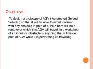
1. OBJECTIVE:
To design a prototype of AGV ( Automated Guided
Vehicle ) so that it will be able to avoid collision
with any obstacle in path of it. Path here will be a
route over which this AGV will travel, in a workshop
of an industry. Obstacle is anything that will lie on
path of AGV while it is performing its travelling.
2. METHODOLOGY:
AGV’s are basically automatic transport vehicle.
‘Automatic ’ word refer here is fully autonomous or in
other words no human interference. This means that
once AGV is on, it will cover its path by itself.
So for this, to achieve, we will have to design a
programmable circuit. Once an AGV is programmed, it
will follow the instruction given by its controller according
to programme.
Now we will have to add electronic components in a
circuit along with microprocessor to avoid collision
during travelling. This electronic component is nothing
but an IR-LED (Infra Red –Light Emitting Diode).
Working of this IR -LED can be shown by following block
diagram:
3.
4. According to above block diagram :
IR-LED’s will detect obstacle: IR-LED’s continuously emit
IR rays. These signals when fall on obstacle, they will
reflect back to IR receiver.
Signal to microcontroller : As soon as IR- receiver
detects IR rays, it will send signal to the microcontroller.
5. Decision By Microcontroller : Now microcontroller will
take decision about this obstacle , and according to
programme embedded in it, it will send signals to motors.
Rotation of Motors : Motor will rotate in the direction
followed by signals. Due to this, new path is selected by
AGV and it will run on that path, finally approaching
towards its target location.
7. TO FABRICATE AGV FOLLOWING COMPONENTS ARE
NEEDED
Mechanical Components: Chassis etc
Electrical Components: motor, power supply etc
Electronic Components: Development board,
microcontroller, IR-LED’s , Motor driver etc
8. CHASSIS
Technical Data for Chassis:
Feature Data
Length: 194mm
Breadth: 105mm
Height: 12mm
The chassis is fabricated from Plastic fibre .
There is a flange which holds the motor
9. Speed 100rpm
Rated voltage 12 V
Motor
Technical specification of Motor:
Motor is the device that converts electrical signal to rotational motion.
Motor used in our project is Plastic DC Geared motor
11. A microcontroller (µC, uC or MCU) is a small computer on a
single integrated circuit containing a processor core,
memory, and programmable input/output peripherals.
Microcontrollers are designed for embedded applications, in
contrast to the microprocessors used in personal computers
or other general purpose applications.
The Microcontroller used in the AGV is ATMEL Atmega 16.
The reasons for using atmega 16 are
Cheap cost
Easy to program
Microcontroller
13. Type: 40Pin Dual Inline Package
Minimum /Maximum Voltage: 4.5/5.5V
Maximum current: 20mA
Number of PORTS 4
No of Data Pins per port 8
Bus width 8Bit
Oscillation Speed 16Mhz
Specification of ATmega 16 (MCU):
14. PIN Name Pin No Connected to:
Vcc 10 +5V
GND 11 GND
XTAL1 12 16Mhz Crystal
XTAL2 13 16Mhz Crystal
PD0 14 Data Pin of Receiever
PB4 3 L293D
PB5 4
PB6 5
PB7 6
Connections:
15. Motor Driver
Motor can not run on power that we get from output PINs of MCU ,
So, there is a need to use a amplifying Current IC that is L293D .
In this IC there is a provision of providing External Voltage up to 36V.
16. Type: 16Pin Dual Inline package
Max Logic Voltage: 5V
Max Supply Voltage: 36V
Channels: 2
Current per channel: 600mA
Technical Specification of L293D
17. IR Emitter and Receiever
IR emitter transmits the IR rays and Receiver that
receives the rays and send signal to MCU
18. Power supply
A power supply is a device that supplies electrical energy
to Development Board and Motors.
24. #include <avr/io.h>
void Drive_Motor(unsigned char LEFT,unsigned char RGHT)
{
if(RGHT==0)//if right == 0 then right motor will stop
{
PORTB&=~_BV(5);
PORTB&=~_BV(4);
}
if(RGHT==1)//if right == 1 then right motor will go forward
{
PORTB&=~_BV(5);
PORTB|=_BV(4);
}
if(RGHT==2)//if right == 2 then right motor will go backward
{
PORTB|=_BV(5);
PORTB&=~_BV(4);
}
if(LEFT==0)//if left == 0 then left motor will stop
{
PORTB&=~_BV(6);
PORTB&=~_BV(7);
//PC2=0;
//PC3=0;
}
if(LEFT==1)//if left == 1 then left motor will go forward
{
PORTB&=~_BV(6);
PORTB|=_BV(7);
}
if(LEFT==2)//if left == 2 then right motor will go backward
{
PORTB|=_BV(6);
PORTB&=~_BV(7);
}
}
25. int main(void)
{
DDRA=0x00; //Set PortA all pins as input
DDRD=0xff; //Set PortD all pins as output
DDRB=0xff; //Set PortB all pins as output
PORTA=0xff; //Enable pullup on all PortA pins
PORTD=0xff; //Make all pins of portD go high
PORTB=0x00; //Make all pins of portB go low
//when looking at the machine from the front
while(1)
{
if((bit_is_clear(PINA, 1)) && (bit_is_clear(PINA, 2)) && (bit_is_clear(PINA, 3))) // if middle 3 on line go straight
{
Drive_Motor(1,1);//all 3 sensors on black line
}
else
if((bit_is_set(PINA, 1)) && (bit_is_clear(PINA, 2)) && (bit_is_clear(PINA, 3)))
{
Drive_Motor(1,0);//left sensor on white patch
}
else
if((bit_is_set(PINA, 1)) && (bit_is_set(PINA, 2)) && (bit_is_clear(PINA, 3)))
{
Drive_Motor(1,0);//left and middle sensor on white patch
}
else
if((bit_is_clear(PINA, 1)) && (bit_is_clear(PINA, 2)) && (bit_is_set(PINA, 3)))
{
Drive_Motor(0,1);//right sensor on white patch
}
else
if((bit_is_clear(PINA, 1)) && (bit_is_set(PINA, 2)) && (bit_is_set(PINA, 3)))
{
Drive_Motor(0,1);//middle & right sensor on white patch
}
}
}
27. Now we have to burn the programme to MCU. For this
purpose we need an interface between MCU and
programming device like laptop or computer. This interface
is known as programmer.
INTERFACE:
programmer