
![Mechanical specification
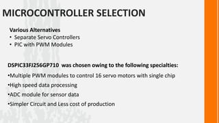
SPECIFICATIONS DETAILS
Material Used Light weight, Low cost Aluminum alloy
Number of links 8
Size of link(mm) 130x62x77
Weight of link(Kg) 0.28
Motion Range of joint(deg) [-90,+90]
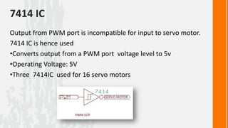
Actuators Servo motor, (Vigor – 6Kg cm Stall Torque)
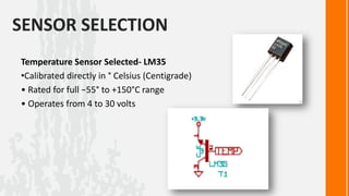
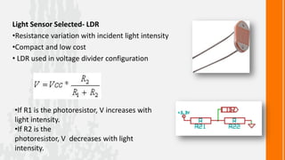
Sensors Temperature Sensor ( LM35 ) Light sensor (LDR)](https://image.slidesharecdn.com/wasp-120417150253-phpapp02/85/Wirelessly-Actuated-Snake-Prototype-8-320.jpg)
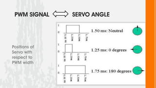
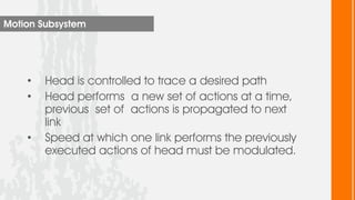
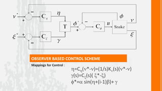
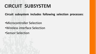
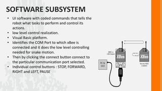
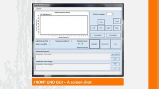
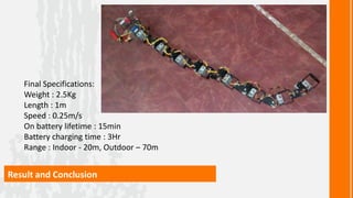
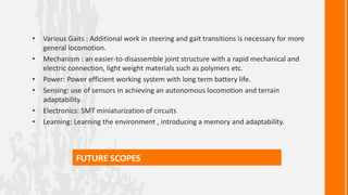
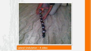

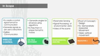
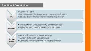
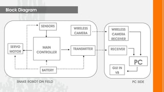
This document describes a wireless snake robot prototype called WASP. It has 8 linked segments that provide multiple degrees of freedom for flexible motion. The robot is intended to demonstrate horizontal and basic vertical movement as a proof of concept. Key components include a microcontroller for motion control, sensors for environmental analysis, and wireless communication between the robot and a PC interface. Algorithms are used to generate servo motor angles from user instructions to achieve the snake-like locomotion. The prototype aims to establish wireless control, sensor data reception and basic on-field movement capabilities. Future work may include improving gaits, mechanism design, power efficiency and adding autonomous capabilities.