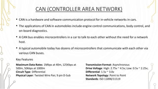
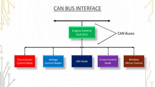
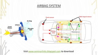
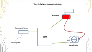
Embedded System in Automobiles
Visit www.seminarlinks.blogspot.com to download
EMBEDDED SYSTEM
• A combination of hardware and software which together form a
component of a larger machine.
• An example of an embedded system is a microprocessor that
controls an automobile engine.
• An embedded system is designed to run on its own without human
intervention, and may be required to respond to events in real
time.
Block Diagram of A Typical Embedded System
CHARACTERISTICS OF EMBEDDED SYSTEMS
• Sophisticated functionality
Often have to run sophisticated algorithms or multiple algorithms. Often
provide sophisticated user interfaces.
• Real-time operation
Must finish operations by deadlines.
• Hard real time: missing deadline causes failure.
• Soft real time: missing deadline results in degraded performance.
Many systems are multi-rate: must handle operations at widely varying rates.
• Low manufacturing cost.
• Low power.
• Designed to tight deadlines by small teams.
APPLICATIONS IN AUTOMOTIVE SYSTEM
• Air Bags
• Traction Control
• The Black Box
• Automatic Parking
• Anti-lock Brake
• Adaptive Cruise
• Heads-up display Control
• Night Vision
• Drive by wire
• Satellite Radio E.g.: XM
• Back-up collision sensor
• Telematics E.g.: OnStar
• Rain-sensing Wipers
• Navigation Systems
• Emission Control
• Tire Pressure Monitor
• Climate Control
CAN (CONTROLLER AREA NETWORK)
• CAN is a hardware and software communication protocol for in-vehicle networks in cars.
• The applications of CAN in automobiles include engine control communications, body control, and
on-board diagnostics.
• A CAN bus enables microcontrollers in a car to talk to each other without the need for a network
host.
• A typical automobile today has dozens of microcontrollers that communicate with each other via
various CAN buses.
Key Features
Transmission Format: Asynchronous
Drive Voltage: High: 2.75v ~ 4.5v; Low: 0.5v ~ 2.25v;
Differential: 1.5v ~ 3.0v
Network Topology: Point to Point
Standards: ISO 11898/11519
Maximum Data Rates: 1Mbps at 40m, 125Kbps at
500m, 50kbps at 1000m
Circuit Type: Differential
Physical Layer: Twisted Wire Pair, 9 pin D-Sub
CAN BUS INTERFACE
Transmission
Control Node
Airbags
Control Nodes
ABS Node
Cruise Control
Node
Window
Mirror Control
Engine Control
Unit ECU CAN Buses
AIRBAG SYSTEM
Visit www.seminarlinks.blogspot.com to download
EDR-ELECTRONIC DATA RECORDERS
• Electronic data recorders- similar to the ‘Black Box’ flight recorders used on
airplanes
• It records a few seconds of a vehicle’s operation immediately before the crash.
• EDRs usually are connected to a vehicle’s air bag control system and
continuously record and rerecord data from connected sensors.
• In an accident in which air bags are deployed , EDR records are captured for
analysis.
EDR BLOCK DIAGRAM
ANTI-LOCK BRAKE SYSTEM (ABS)
The antilock braking system is designed to
prevent wheels locking or skidding, no
matter how hard brakes are applied, or
how slippery the road surface.
The primary components of the ABS
braking system are:
• Electronic control unit (ECU)
• Hydraulic control unit or modulator
• Power booster & master cylinder
assembly
• Wheel sensor unit
BASIC ANTI-LOCK BRAKE SYSTEM
sensor sensor
sensorsensor
Brake
BrakeBrake
Brake
ABS
control
module
Hydraulic
Pump
PRINCIPLE OF FUNCTIONING
• Wheel-speed sensors detect whether a wheel is showing a tendency to lock-up.
• In case of a lock-up tendency, the electronic control unit reduces the braking
pressure individually at the wheel concerned.
• High-speed correction of the braking pressure up to shortly before the lock-up
threshold.
• The brake-fluid return together with the closed-loop brake circuits makes this a safe,
reliable, and cost-effective system.
The vehicle is remains no longer steerable
when the driver hits the brake
The vehicle remains steerable
even during panic braking
TRACTION CONTROL
• Traction Control works by regulating the distribution of torque to
each wheel of the vehicle.
• This stops the tires from spinning, and ensures that the car moves
forward.
• It also ensures that brake pressure is electronically controlled at
each wheel to suppress wheel spin and maintain optimum traction,
so drive force is optimally distributed to all four wheels.
VEHICLE STABILITY CONTROL (VSC)
• System that ensures control in concerning situations the way ABS does under
braking and TRC does under acceleration .
• The VSC system utilizes electronics sensors in conjunction with the ABS and
TRC hardware to help control any potential understeer or oversteer situations.
• Understeer is when the vehicle loses front-wheel traction and wants to push
forward nose first
• OverSteer is when the rear wheels lose traction and tail begins to slide
CRUISE CONTROL SYSTEM
• The cruise control system controls the
speed of the car by adjusting the throttle
position, so it needs sensors to tell it the
speed and throttle position.
• It also needs to monitor the controls so it
can tell what the desired speed is and
when to disengage.
Adaptive Cruise Control
INTELLIGENT CRUISE CONTROL
• Cooperative Adaptive Cruise Control with Collision Warning (CACC + CW)
• CACC: Cruise at given speed when the road is clear (cruise control) otherwise follow the
car in front, using radar (adaptive) and/or communications (cooperative).
• CW: Warn the driver when an object is being approached too fast, or is too close.
Principle of Operation of
Adaptive Cruise Control
• CACC system is effective when the
adaptive cruise control fails to perform
correctly due to the radar's line-of-
sight scanning.
• When the car approaches a sharp
curve, the DSRC system warns the
adaptive cruise control system of any
slow moving vehicles just around the
turn.
• Dedicated Short Range
Communications (DSRC) is a data-only
automotive communication protocol.
• Vehicle to vehicle DSRC would enable information about an approaching
emergency vehicle to be relayed from vehicle to vehicle forward through traffic.
• This would help to clear the way for the emergency vehicle and reduce the risk to
other vehicles.
APPROACHING EMERGENCY VEHICLE WARNING
Information about
approaching emergency
vehicle sent ahead through
vehicle using DSRC
DRIVE BY WIRE
• This technology replaces the traditional
mechanical control systems with electronic
control systems using electromechanical
actuators and human-machine interfaces.
• It means Drive by wire replaces mechanical
connections – push rods, rack & pinion,
steering columns, overhead cams, cables –
by mechatronic connections – sensors,
actuators, embedded microprocessors,
control software
Drive by wire involves 3 main
systems:
• Steer by Wire
• Throttle by Wire
• Brake by Wire
Visit www.seminarlinks.blogspot.com to download
CONCLUSION
• In the recent years, more and more equipment in automotive are changing
from mechanical systems to electronic systems.
• Embedded system is a core of vehicle electronic systems because of its
flexibility and versatility.
• The electronics revolution has influenced almost every aspect of automotive
design including the powertrain, fuel combustion, crash protection and the
creation of a comfortable cabin and nearly wireless environment.
• It is necessary to pay more attention to the fields of environments, safety and
security, which are the most significant and challenge field of automotive
embedded system design.
REFERENCES
• www.wikipedia.org
• http://www.cvel.clemson.edu/
• http://auto.howstuffworks.com/
• http://www.toyota.com.au/
• http://www.cdxetextbook.com/
Thank You
Visit www.seminarlinks.blogspot.com to download

Embedded System in Automobiles

  • 1.
    Embedded System inAutomobiles Visit www.seminarlinks.blogspot.com to download
  • 2.
    EMBEDDED SYSTEM • Acombination of hardware and software which together form a component of a larger machine. • An example of an embedded system is a microprocessor that controls an automobile engine. • An embedded system is designed to run on its own without human intervention, and may be required to respond to events in real time.
  • 3.
    Block Diagram ofA Typical Embedded System
  • 4.
    CHARACTERISTICS OF EMBEDDEDSYSTEMS • Sophisticated functionality Often have to run sophisticated algorithms or multiple algorithms. Often provide sophisticated user interfaces. • Real-time operation Must finish operations by deadlines. • Hard real time: missing deadline causes failure. • Soft real time: missing deadline results in degraded performance. Many systems are multi-rate: must handle operations at widely varying rates. • Low manufacturing cost. • Low power. • Designed to tight deadlines by small teams.
  • 5.
    APPLICATIONS IN AUTOMOTIVESYSTEM • Air Bags • Traction Control • The Black Box • Automatic Parking • Anti-lock Brake • Adaptive Cruise • Heads-up display Control • Night Vision • Drive by wire • Satellite Radio E.g.: XM • Back-up collision sensor • Telematics E.g.: OnStar • Rain-sensing Wipers • Navigation Systems • Emission Control • Tire Pressure Monitor • Climate Control
  • 7.
    CAN (CONTROLLER AREANETWORK) • CAN is a hardware and software communication protocol for in-vehicle networks in cars. • The applications of CAN in automobiles include engine control communications, body control, and on-board diagnostics. • A CAN bus enables microcontrollers in a car to talk to each other without the need for a network host. • A typical automobile today has dozens of microcontrollers that communicate with each other via various CAN buses. Key Features Transmission Format: Asynchronous Drive Voltage: High: 2.75v ~ 4.5v; Low: 0.5v ~ 2.25v; Differential: 1.5v ~ 3.0v Network Topology: Point to Point Standards: ISO 11898/11519 Maximum Data Rates: 1Mbps at 40m, 125Kbps at 500m, 50kbps at 1000m Circuit Type: Differential Physical Layer: Twisted Wire Pair, 9 pin D-Sub
  • 8.
    CAN BUS INTERFACE Transmission ControlNode Airbags Control Nodes ABS Node Cruise Control Node Window Mirror Control Engine Control Unit ECU CAN Buses
  • 9.
  • 10.
    EDR-ELECTRONIC DATA RECORDERS •Electronic data recorders- similar to the ‘Black Box’ flight recorders used on airplanes • It records a few seconds of a vehicle’s operation immediately before the crash. • EDRs usually are connected to a vehicle’s air bag control system and continuously record and rerecord data from connected sensors. • In an accident in which air bags are deployed , EDR records are captured for analysis.
  • 12.
  • 13.
    ANTI-LOCK BRAKE SYSTEM(ABS) The antilock braking system is designed to prevent wheels locking or skidding, no matter how hard brakes are applied, or how slippery the road surface. The primary components of the ABS braking system are: • Electronic control unit (ECU) • Hydraulic control unit or modulator • Power booster & master cylinder assembly • Wheel sensor unit
  • 14.
    BASIC ANTI-LOCK BRAKESYSTEM sensor sensor sensorsensor Brake BrakeBrake Brake ABS control module Hydraulic Pump
  • 15.
    PRINCIPLE OF FUNCTIONING •Wheel-speed sensors detect whether a wheel is showing a tendency to lock-up. • In case of a lock-up tendency, the electronic control unit reduces the braking pressure individually at the wheel concerned. • High-speed correction of the braking pressure up to shortly before the lock-up threshold. • The brake-fluid return together with the closed-loop brake circuits makes this a safe, reliable, and cost-effective system.
  • 16.
    The vehicle isremains no longer steerable when the driver hits the brake The vehicle remains steerable even during panic braking
  • 17.
    TRACTION CONTROL • TractionControl works by regulating the distribution of torque to each wheel of the vehicle. • This stops the tires from spinning, and ensures that the car moves forward. • It also ensures that brake pressure is electronically controlled at each wheel to suppress wheel spin and maintain optimum traction, so drive force is optimally distributed to all four wheels.
  • 18.
    VEHICLE STABILITY CONTROL(VSC) • System that ensures control in concerning situations the way ABS does under braking and TRC does under acceleration . • The VSC system utilizes electronics sensors in conjunction with the ABS and TRC hardware to help control any potential understeer or oversteer situations. • Understeer is when the vehicle loses front-wheel traction and wants to push forward nose first • OverSteer is when the rear wheels lose traction and tail begins to slide
  • 20.
    CRUISE CONTROL SYSTEM •The cruise control system controls the speed of the car by adjusting the throttle position, so it needs sensors to tell it the speed and throttle position. • It also needs to monitor the controls so it can tell what the desired speed is and when to disengage.
  • 21.
  • 22.
    INTELLIGENT CRUISE CONTROL •Cooperative Adaptive Cruise Control with Collision Warning (CACC + CW) • CACC: Cruise at given speed when the road is clear (cruise control) otherwise follow the car in front, using radar (adaptive) and/or communications (cooperative). • CW: Warn the driver when an object is being approached too fast, or is too close. Principle of Operation of Adaptive Cruise Control
  • 24.
    • CACC systemis effective when the adaptive cruise control fails to perform correctly due to the radar's line-of- sight scanning. • When the car approaches a sharp curve, the DSRC system warns the adaptive cruise control system of any slow moving vehicles just around the turn. • Dedicated Short Range Communications (DSRC) is a data-only automotive communication protocol.
  • 26.
    • Vehicle tovehicle DSRC would enable information about an approaching emergency vehicle to be relayed from vehicle to vehicle forward through traffic. • This would help to clear the way for the emergency vehicle and reduce the risk to other vehicles. APPROACHING EMERGENCY VEHICLE WARNING Information about approaching emergency vehicle sent ahead through vehicle using DSRC
  • 27.
    DRIVE BY WIRE •This technology replaces the traditional mechanical control systems with electronic control systems using electromechanical actuators and human-machine interfaces. • It means Drive by wire replaces mechanical connections – push rods, rack & pinion, steering columns, overhead cams, cables – by mechatronic connections – sensors, actuators, embedded microprocessors, control software
  • 28.
    Drive by wireinvolves 3 main systems: • Steer by Wire • Throttle by Wire • Brake by Wire
  • 29.
  • 32.
    CONCLUSION • In therecent years, more and more equipment in automotive are changing from mechanical systems to electronic systems. • Embedded system is a core of vehicle electronic systems because of its flexibility and versatility. • The electronics revolution has influenced almost every aspect of automotive design including the powertrain, fuel combustion, crash protection and the creation of a comfortable cabin and nearly wireless environment. • It is necessary to pay more attention to the fields of environments, safety and security, which are the most significant and challenge field of automotive embedded system design.
  • 33.
    REFERENCES • www.wikipedia.org • http://www.cvel.clemson.edu/ •http://auto.howstuffworks.com/ • http://www.toyota.com.au/ • http://www.cdxetextbook.com/
  • 34.