Download as PPSX, PPTX
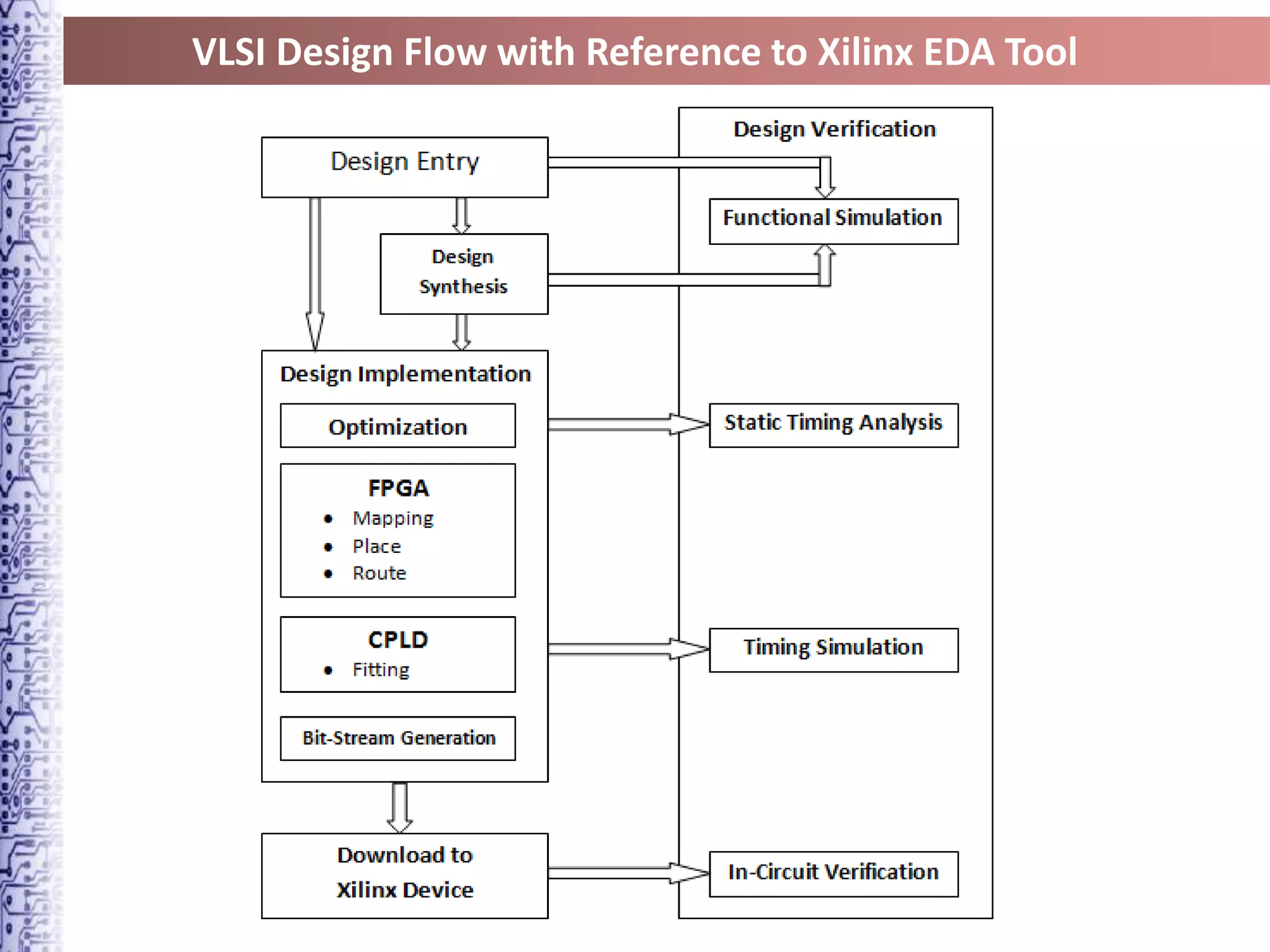

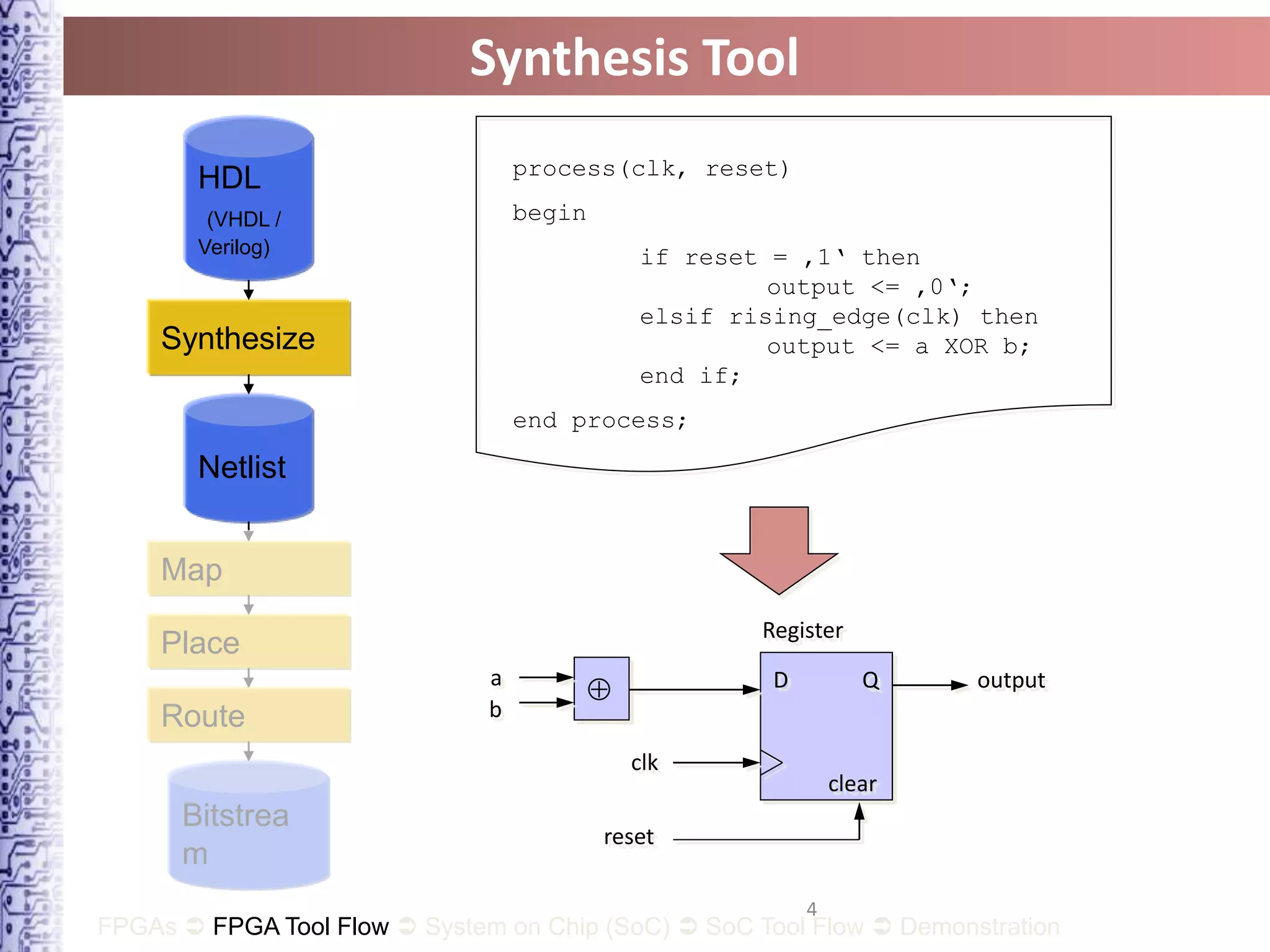
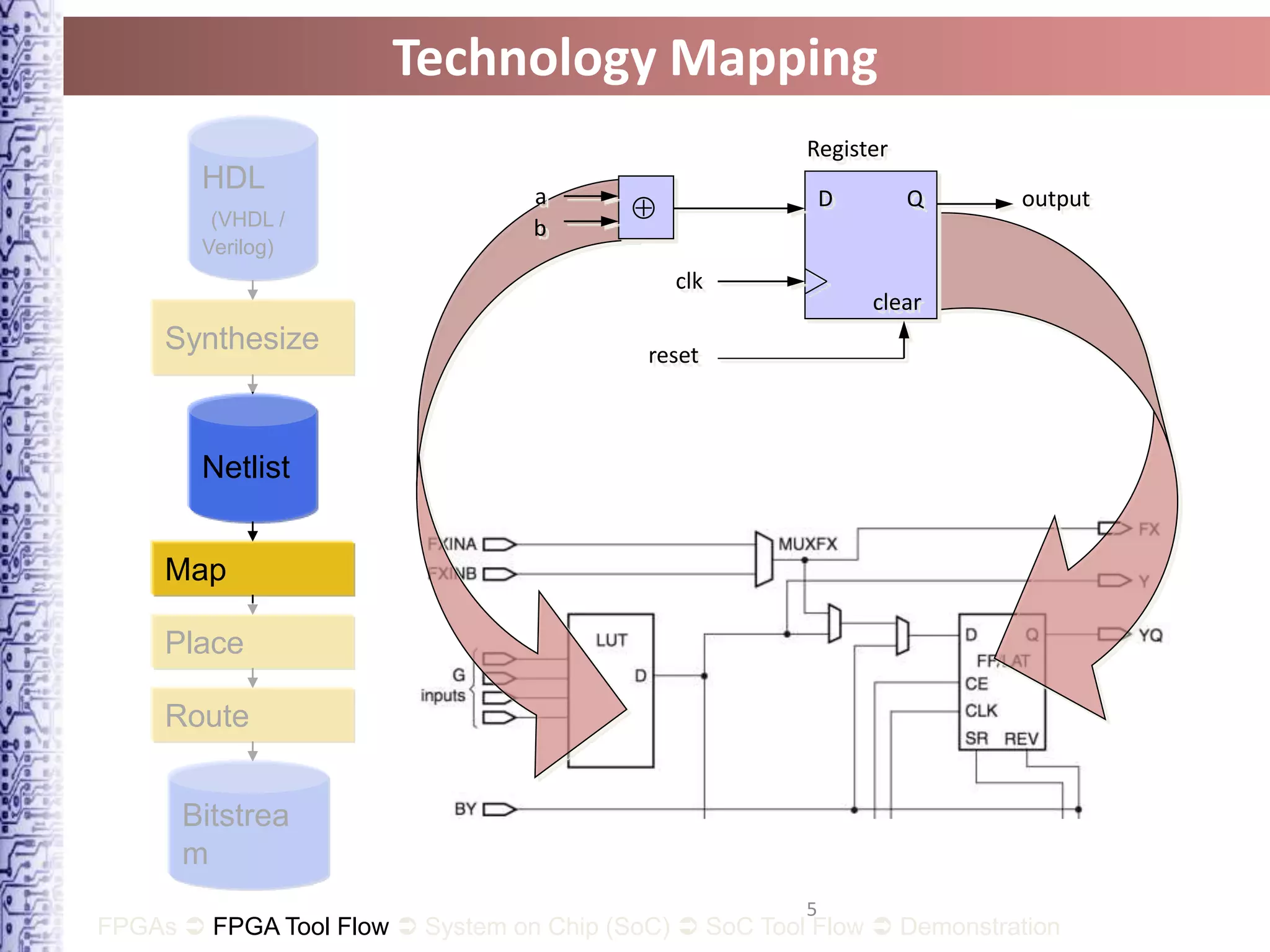
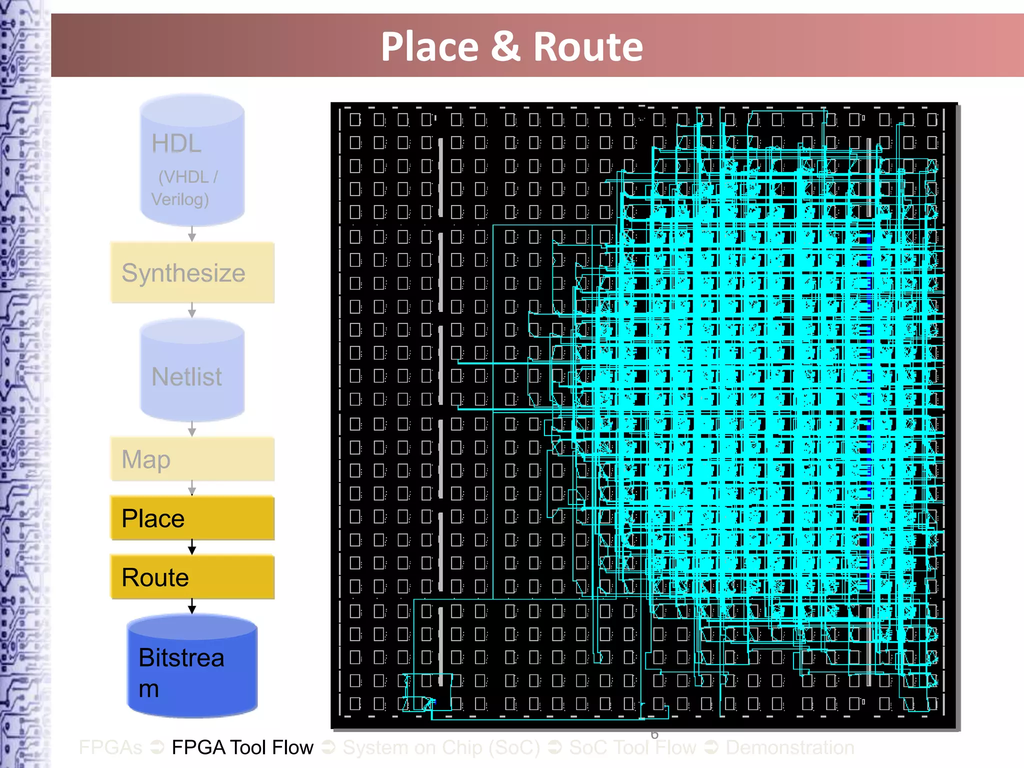


The document describes the VLSI design flow with reference to the Xilinx FPGA tool. It involves modeling the system using a hardware description language like VHDL or Verilog. The synthesis tool then generates a netlist from this code. This netlist is mapped to the FPGA technology by inferring components. These components are placed on the chip and connecting signals are routed through the interconnection network to produce a bitstream that can configure the FPGA.