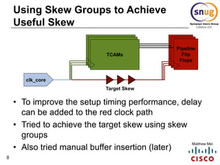
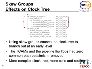
Implementing useful skew through skew groups or manual buffer insertion can improve timing in a large memory block design. Skew groups define a target skew value for groups of clock pins before clock tree synthesis, resulting in a smaller clock tree, lower power increase, and less routing complexity compared to manual buffer insertion. Manual insertion precisely controls skew by adding buffers but dramatically increases clock cell count and power consumption versus skew groups. Both methods effectively improved setup timing for the memory block design.


![6
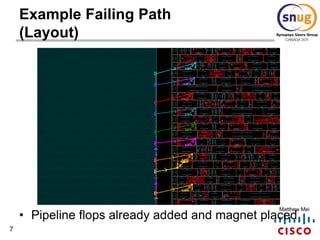
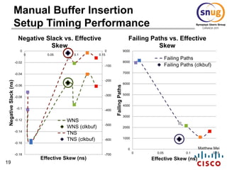
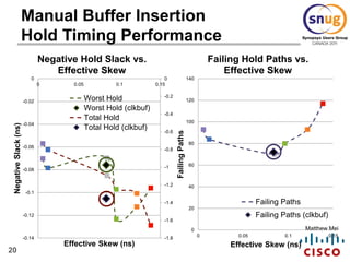
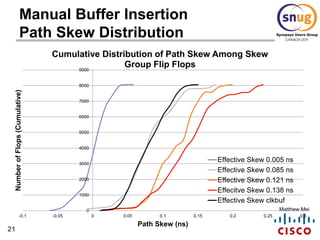
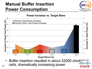
Matthew Mei
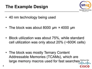
Example Failing Path
(Timing Report)
Path Type: max
Point Incr Path
----------------------------------------------------------
clock clk_core (rise edge) 0.0000 0.0000
clock network delay (propagated) 1.1783 1.1783
w/m_36x1/CLK 0.0000 1.1783 r
w/m_36x1/QXY[13] 1.4831 2.6614 f
w/r0_data_read1_s_36x1_13_ (net) 0.0000 2.6614 f
w/r1_data_read1_s_36x1_reg_13_/D 0.0000 & 2.6614 f
data arrival time 2.6614
clock clk_core (rise edge) 1.6670 1.6670
clock network delay (propagated) 1.0460 2.7130
clock uncertainty -0.0580 2.6550
w/r1_data_read1_s_36x1_reg_13_/CK 0.0000 2.6550 r
library setup time -0.1197 2.5353
data required time 2.5353
----------------------------------------------------------
data required time 2.5353
data arrival time -2.6614
----------------------------------------------------------
slack (VIOLATED) -0.1261](https://image.slidesharecdn.com/snugpresentationfinal4-140504173230-phpapp02/85/Implementing-Useful-Clock-Skew-Using-Skew-Groups-6-320.jpg)


![[Back2School] Timing Checks- Chapter 5.pdf](https://cdn.slidesharecdn.com/ss_thumbnails/specialtimingchecks-250609185635-cf7ed43c-thumbnail.jpg?width=640&height=640&fit=bounds)