Download as PPSX, PPTX
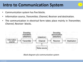
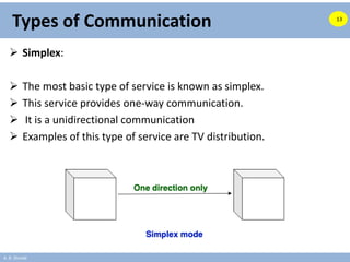
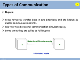
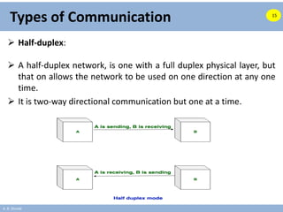
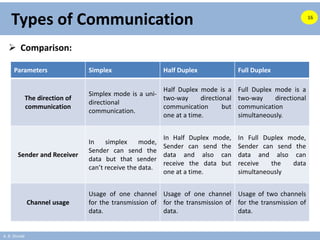
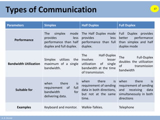
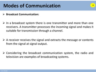
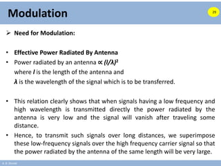
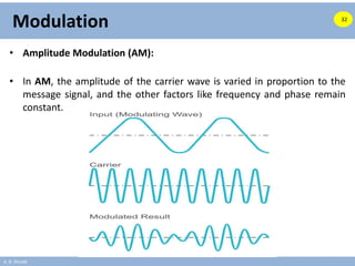
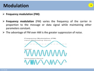
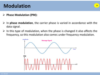
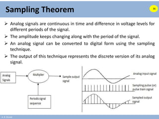
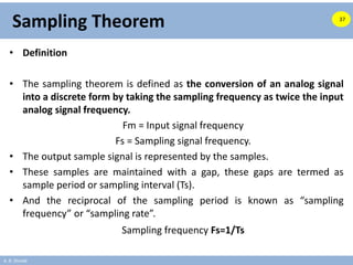
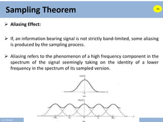
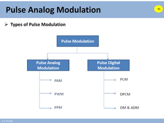
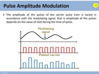


This document provides an introduction to communication systems. It discusses the basic blocks of a communication system including the information source, transmitter, channel, receiver and destination. It also describes different types of communication systems such as simplex, duplex and half-duplex. Modes of communication including broadcast and point-to-point are explained. The document then covers modulation techniques, the need for modulation, and classifications of analog and digital modulation. It introduces the sampling theorem and discusses aliasing. Finally, it discusses pulse amplitude modulation as a type of pulse analog modulation.