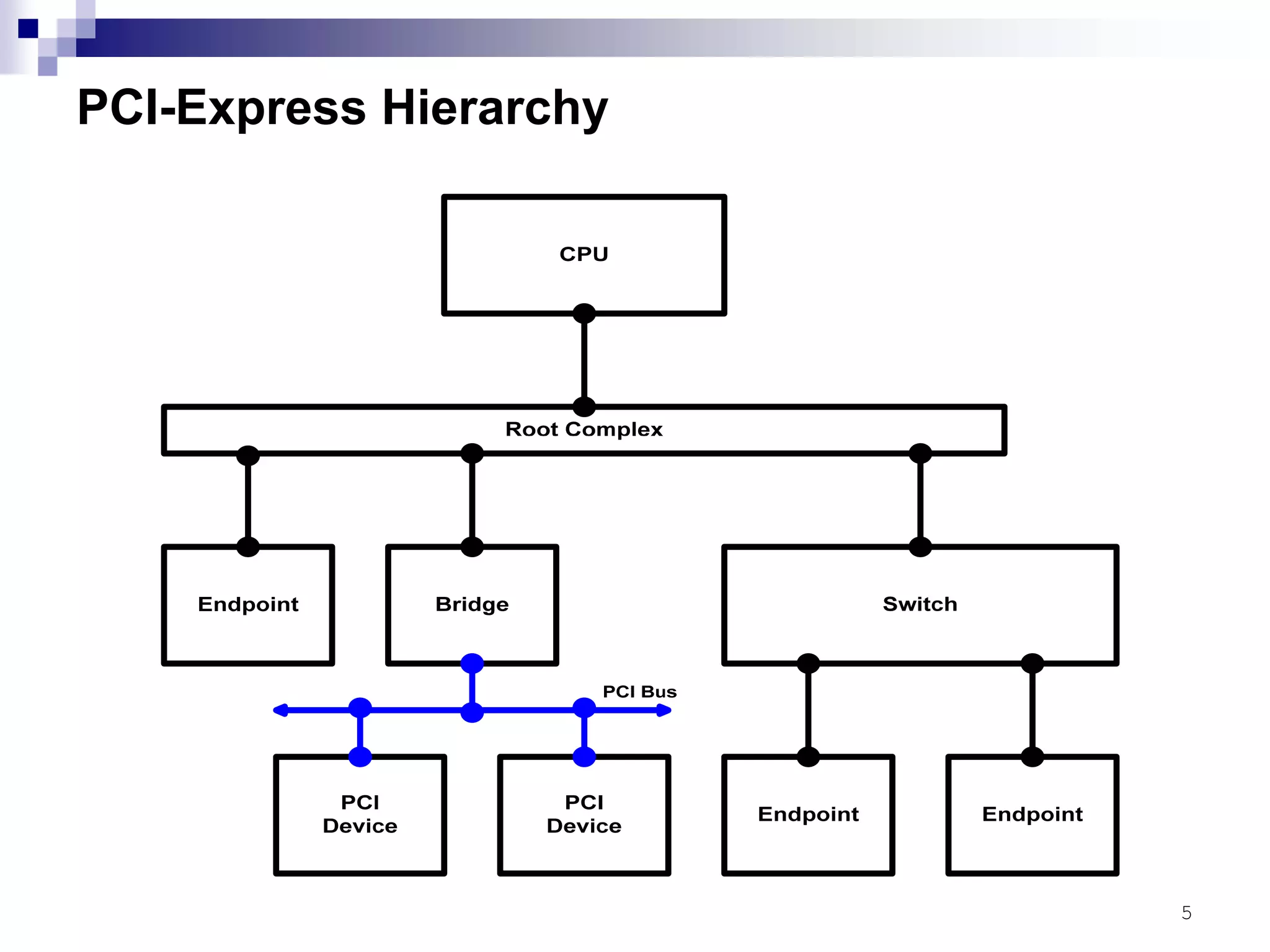
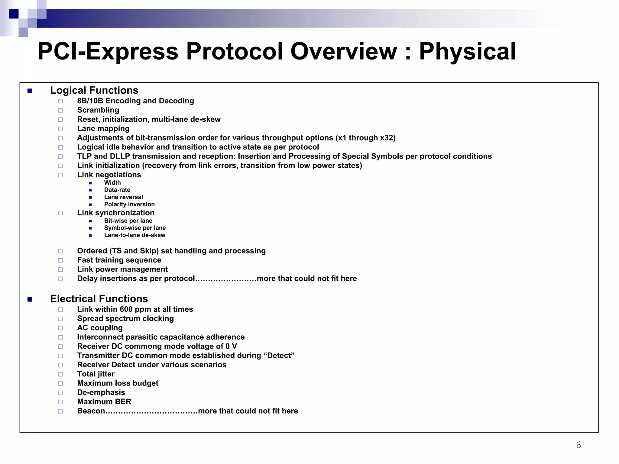
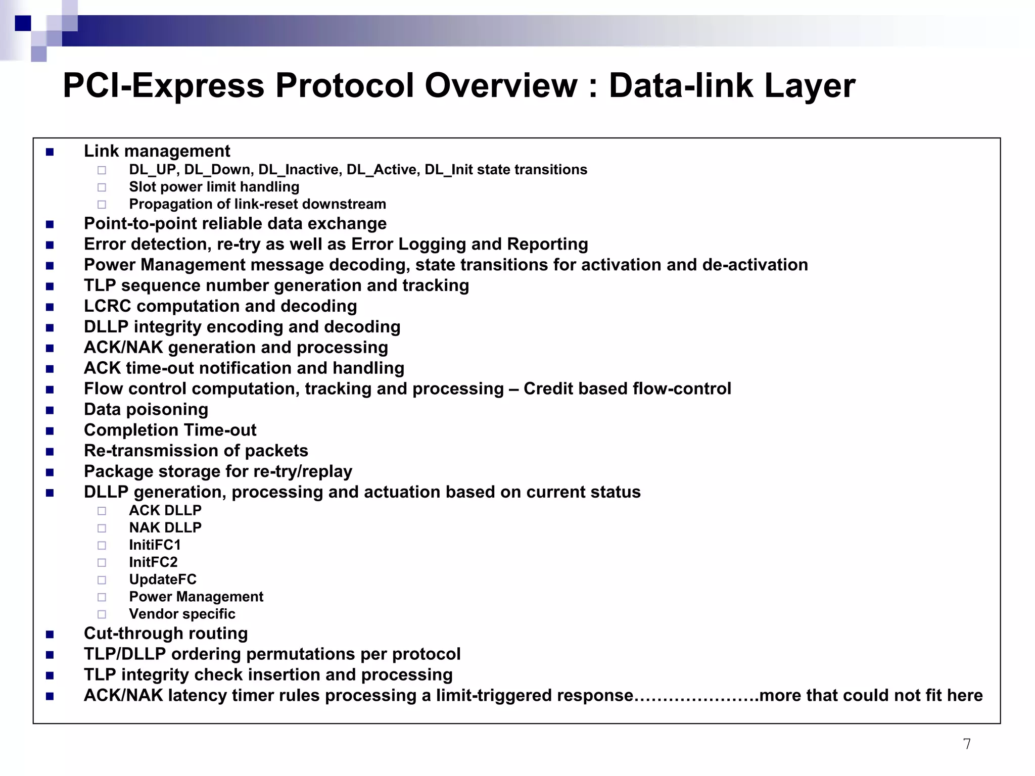
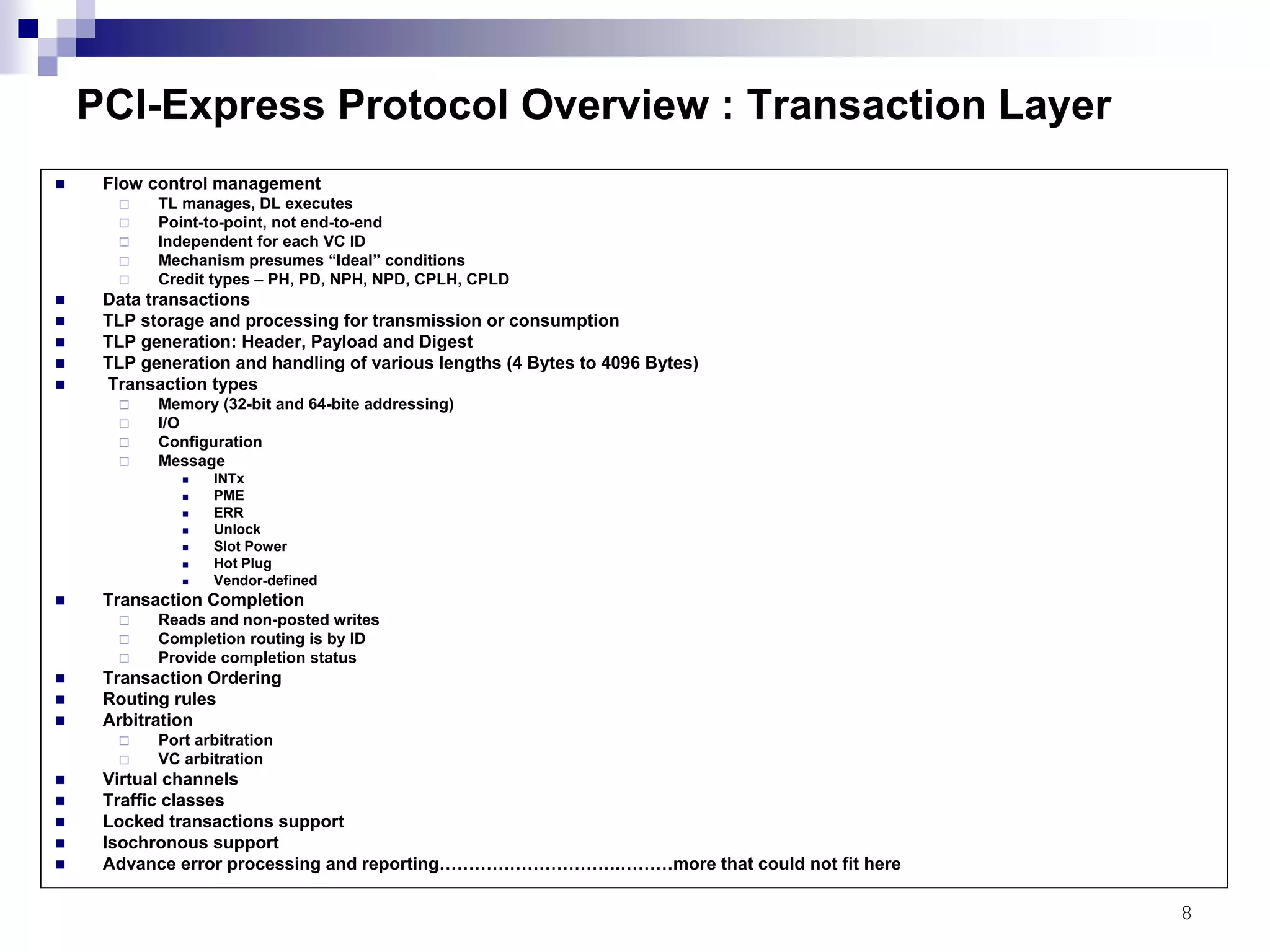
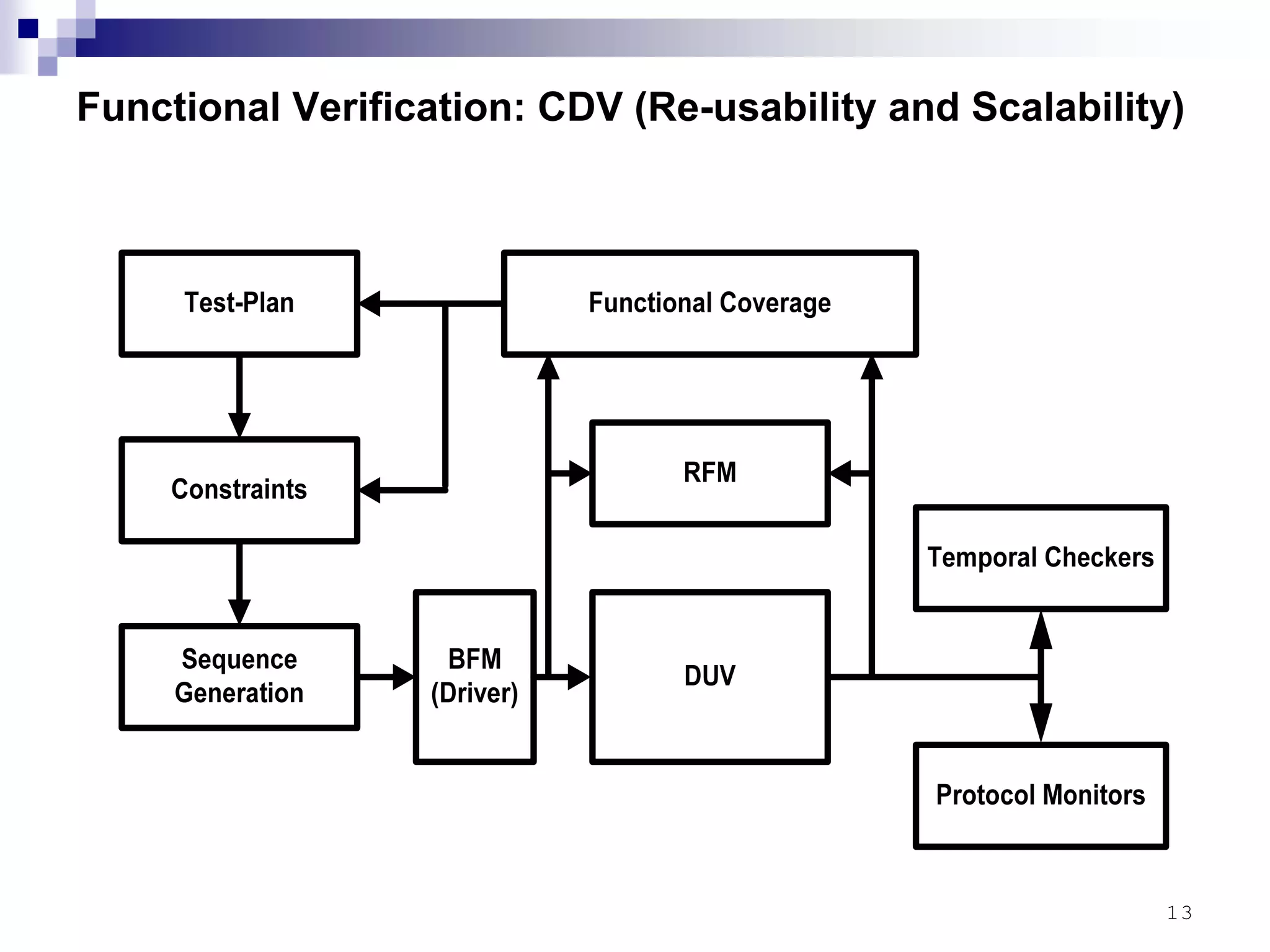
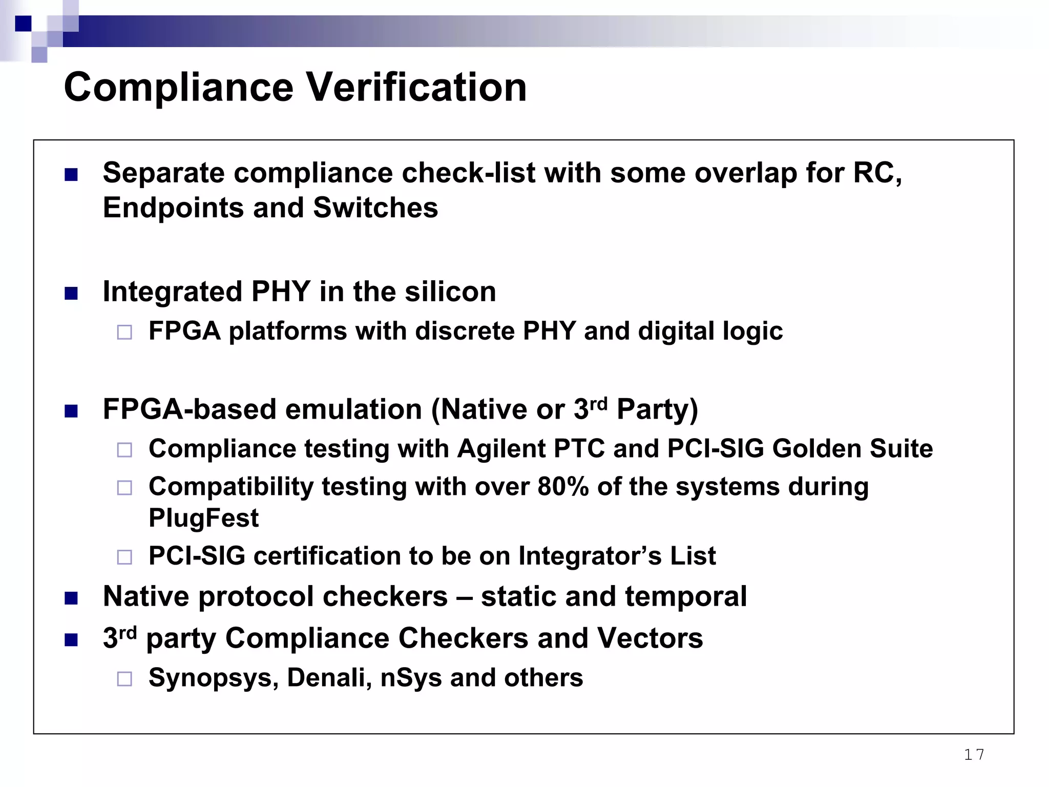
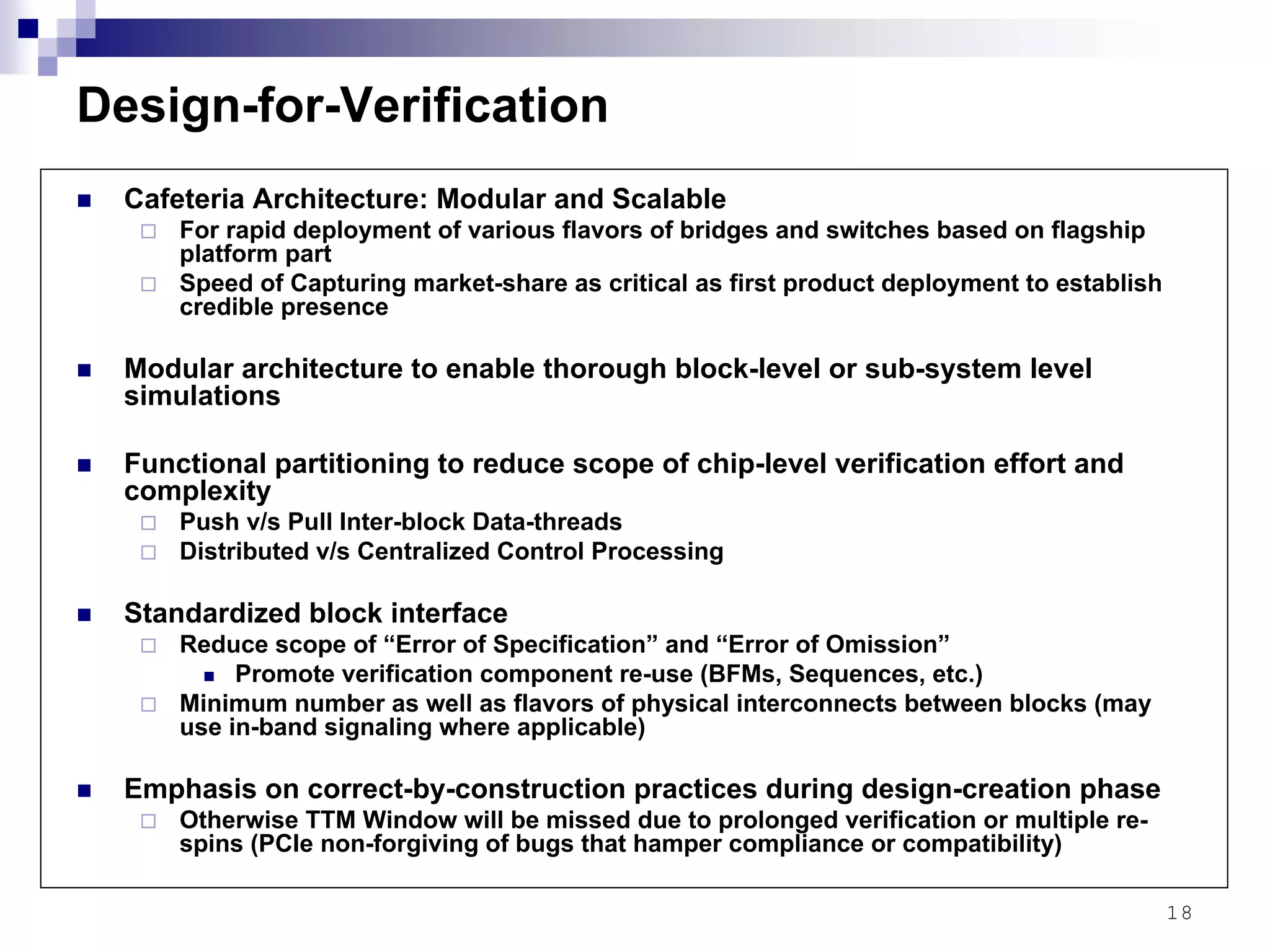
Verification Strategy for PCI-Express
Presenter: Pradip Thaker
July 4th, 2008
2
Outline
PCI-Express Protocol Overview
Verification Paradigm
Design-for-Verification (Well-aligned implementation and
verification architectures)
A key ingredient for a timely verification closure
3
PCI to PCI Express
Limitations of PCI
Not enough bandwidth
32-bit/33 MHz (132 MB/s)
64-bit/66 MHz (528 MB/s)
Shared bus bandwidth
No support for Isochronous applications (TDM or Synchronous Traffic application)
Cost of hardware for parallel busses
Evolution Path
Growing faster is the only possibility (not wider)
Point-to-point communication (Shared bus connectivity impossible above 100/150
MHz)
CDR architecture (Speed limitation of a synchronous bus above few hundred MHz)
Backward compatibility – a must
Fast forward to future – PCI Express (PCIe)
Packet-level data-units over high-speed SERDES based connectivity
Layered architecture – much like networking protocols
Mechanical, Physical, Data-link, Transaction, Software and System Layers
Compatible with existing PCI software infrastructure
Weird wedding of two distinct architectural and business practices – Networking and
Computer
Creation of nightmarish scenario for chip verification (Details on later slides)
4
PCI-Express Protocol Overview - Terminology
Dual Simplex – a related set of two differential pairs (Tx and Rx)
Lane – “Dual Simplex” when PCI-Express compliant
Port – A group of Txs and Rxs within a single device that represent a single connection
to PCI-Express fabric
Link – Two ports and the collection of lanes that interconnect them
x1, x4, x8, xN – Number of lanes within a port or a link
Upstream – Flow of traffic towards the CPU or a port that establishes link in that
direction within the hierarchy
Downstream – Flow of traffic away from the CPU or a port that establishes a link in that
direction within the hierarchy
Ingress Port – the portion of a PCIe port that receives the incoming traffic
Egress Port – the portion of a PCIe port that transmits outgoing traffic
Root Complex – The combination of a PCIe host bridge and one or more downstream
ports
Endpoint – A device that terminates a path within the hierarchy
Bridge – A device that physically and electrically connects PCIe to another protocol
Switch – A device that provides a physical connection between two or more PCIe ports
5
PCI-Express Hierarchy
6
PCI-Express Protocol Overview : Physical
Logical Functions
8B/10B Encoding and Decoding
Scrambling
Reset, initialization, multi-lane de-skew
Lane mapping
Adjustments of bit-transmission order for various throughput options (x1 through x32)
Logical idle behavior and transition to active state as per protocol
TLP and DLLP transmission and reception: Insertion and Processing of Special Symbols per protocol conditions
Link initialization (recovery from link errors, transition from low power states)
Link negotiations
Width
Data-rate
Lane reversal
Polarity inversion
Link synchronization
Bit-wise per lane
Symbol-wise per lane
Lane-to-lane de-skew
Ordered (TS and Skip) set handling and processing
Fast training sequence
Link power management
Delay insertions as per protocol……………………more that could not fit here
Electrical Functions
Link within 600 ppm at all times
Spread spectrum clocking
AC coupling
Interconnect parasitic capacitance adherence
Receiver DC commong mode voltage of 0 V
Transmitter DC common mode established during “Detect”
Receiver Detect under various scenarios
Total jitter
Maximum loss budget
De-emphasis
Maximum BER
Beacon………………………………more that could not fit here
7
PCI-Express Protocol Overview : Data-link Layer
Link management
DL_UP, DL_Down, DL_Inactive, DL_Active, DL_Init state transitions
Slot power limit handling
Propagation of link-reset downstream
Point-to-point reliable data exchange
Error detection, re-try as well as Error Logging and Reporting
Power Management message decoding, state transitions for activation and de-activation
TLP sequence number generation and tracking
LCRC computation and decoding
DLLP integrity encoding and decoding
ACK/NAK generation and processing
ACK time-out notification and handling
Flow control computation, tracking and processing – Credit based flow-control
Data poisoning
Completion Time-out
Re-transmission of packets
Package storage for re-try/replay
DLLP generation, processing and actuation based on current status
ACK DLLP
NAK DLLP
InitiFC1
InitFC2
UpdateFC
Power Management
Vendor specific
Cut-through routing
TLP/DLLP ordering permutations per protocol
TLP integrity check insertion and processing
ACK/NAK latency timer rules processing a limit-triggered response………………….more that could not fit here
8
PCI-Express Protocol Overview : Transaction Layer
Flow control management
TL manages, DL executes
Point-to-point, not end-to-end
Independent for each VC ID
Mechanism presumes “Ideal” conditions
Credit types – PH, PD, NPH, NPD, CPLH, CPLD
Data transactions
TLP storage and processing for transmission or consumption
TLP generation: Header, Payload and Digest
TLP generation and handling of various lengths (4 Bytes to 4096 Bytes)
Transaction types
Memory (32-bit and 64-bite addressing)
I/O
Configuration
Message
INTx
PME
ERR
Unlock
Slot Power
Hot Plug
Vendor-defined
Transaction Completion
Reads and non-posted writes
Completion routing is by ID
Provide completion status
Transaction Ordering
Routing rules
Arbitration
Port arbitration
VC arbitration
Virtual channels
Traffic classes
Locked transactions support
Isochronous support
Advance error processing and reporting………………………….………more that could not fit here
9
PCI-Express Protocol Overview: Summary
Open standard containing over 500 pages
Many more pages of supporting literature
Each line of each page in the standards document is a cryptic
edict dictating a specific behavior for each condition
and not a detailed explanation about behavior or implementation
Much space for protocol detail misinterpretation resulting into
mal-function or non-compliance
Hundreds of configuration bits – each controlling a complex
behavior within the chip with strict adherence to standard dictate
to guarantee backward software compatibility
No wiggle room to claim bug as a feature!!!
10
Verification Paradigm
Chips based on Open-Standard – Pressure Points
Technology/Feature differentiator – Marginal or Non-existing
Commodity product – Power, Performance and Price
Time-to-market – Very Critical
First product – To Establish Credible Presence
Sub-sequent products with various flavors – To Capture Market Share
Bridges: PCI-to-PCIe, SATA-to-PCIe, 1394-to-PCIe, USB-to-PCIe etc.
Switches: 4-port x1 throughput, 4-port x4 throughput, 8-port x4 throughput, etc.
Root Complex: x1 throughput, x4 throughput, etc.
Quality of First Silicon – Critical
Verification Plays A Major Role in Success of Chips based on Open-Standard
Addresses Two Key Aspects: TTM and Quality of Silicon
Verification Execution: Focal Points
Functionality
Performance
Interoperability (Compliance and Compatibility)
Verification Platform Architecture and Methodology: Focal Points
Re-usability
Scalability (Modularity)
Comprehensiveness (with leveraging of automation)
11
Verification Strategy: A Broader Definition
Verification – A vehicle to deliver chips with “Zero Bugs(!)”,
Compliance and Superior performance
Performance Modeling (C/C++/SystemC)
Architecture and Micro-architecture of Key Data and Control Paths
RTL Verification
FPGA-based Emulation
Compliance and Compatibility testing
PCI-SIG certification to be on Integrator’s List
Performance verification
3rd party Compliance Checkers and Vectors
Mixed-signal Simulations
12
Functional Verification: Four Pillars
Coverage-driven constrained-random testing with reference models (HVLs)
Reference Model (RFM)
Temporal Checkers
Protocol Monitors
Sequence Generators
Constraints
Functional Coverage
Test-plan
Assertion-based verification for key building blocks
Detects design errors at the source – increases observability and decreases debug-time
Can identify subtle bugs that may be hard to reach with SBV
Black-box assertions – Protocol oriented
Effective for size/complexity to an extent (memory-size and run-time limitations)
Suitable for block-level deployment rather than end-to-end chip-level stand-alone verification
method
Complex properties are verified through bounded-proof (neither proven nor falsified)
Effective for control-path oriented logic (state space exploration rather than data-path logic)
verification
Assertions when written by engineer other than designer can help detect specification
(interpretation) class of errors
Asynchronous clock-domain simulations
Power-domain simulations – Power Management Compliance Check-list
Improper Buffer Insertion, Missing Level Shifters, Missing Power Good, Power Sequencing Tests
13
Functional Verification: CDV (Re-usability and Scalability)
14
Functional Verification: Golden Rules for RFM
Reference Model shall be independent of the DUT implementation
Reference Model to be created by engineer other than designer of the block
Reference Model created in high-level language and hence it does not have any low-
level mechanics analogous to RTL implementation to realize functionality
Reference Model shall support co-simulation with the DUT in order to predict
and verify run-time behavior
Reference Model for each block shall be created such that it can be integrated
into chip-level verification environment seamlessly
Hybrid Modeling
Control paths: Cycle-accurate modeling
Data paths: Packet-accurate or Data-unit-accurate modeling
Fully cycle-accurate model is maintenance nightmare as well as a cumbersome task
without significant value-add to verification quality
Comprehensiveness (with leveraging of automation)
CDV is only as powerful as comprehensiveness of automated checking features of
reference model and monitors
Can run millions of RTG cycles with comprehensive reference model and monitors
without much manual overhead
15
Performance Verification
Performance Parameters (to be supported with variable sized packets across mixed-traffic
types, across all traffic patterns, mixed VCs and mixed-packet sizes)
Aggregate Throughput
Latency (to be balanced against power dissipation)
Jitter in Latency
Availability/Blocking – Internal back-pressure
N+1 Performance limitation (small TLPs back-to-back)
Flow-control credits
Load distribution and balancing (peer-to-peer as well as vertical traffic flows with
mixed of traffic types, VCs and packet sizes)
Link utilization – No bubbles within or between TLPs (really challenging for cut-
through mode)
Zero tolerance for packet loss
Zero tolerance for wrong packet routing
20% overhead lost in 8B/10B coding
Small TLPs with header as well as DL layer overhead impacting transaction layer efficiency
even with 100% link utilization
Traffic-aware flow-control credit updates (large and small TLPs)
Performance Modeling (C/C++/SystemC)
Architecture and Micro-architecture of Key Data and Control Paths
FPGA-based Emulation
RTL Verification – Not an adequate method for performance testing for PCIe development
16
Compliance Verification
Electrical Compliance Check-list
Signal Quality Analysis
Eye pattern, jitter and BER analysis
Signaling for upstream and downstream
Jitter Analysis DLL
Clock recovery
Interpolation
Transition/non-transition eye points
Data-Link Layer Compliance Check-list
Reserved Fields testing
NAK Response
Replay Timer
Replay Count
Link Retrain
Replay TLP Order
Bad CRC
Undefined Packet
Bad Sequence Number
Duplicate TLP
Transaction Layer Compliance Check-list
Completion request, completion time-out, read-data
Messaging – Legacy interrupts, Native power management, Hot-plug, Error Signaling
Flow Control – Initialization, Transmit and Receive States, Negotiated Link Width
Virtual Channel
System Architecture/Platform-configuration Check-list
Capability registers testing
Default values
Stress test
Slot reporting
Hot plug event reporting
17
Compliance Verification
Separate compliance check-list with some overlap for RC,
Endpoints and Switches
Integrated PHY in the silicon
FPGA platforms with discrete PHY and digital logic
FPGA-based emulation (Native or 3rd Party)
Compliance testing with Agilent PTC and PCI-SIG Golden Suite
Compatibility testing with over 80% of the systems during
PlugFest
PCI-SIG certification to be on Integrator’s List
Native protocol checkers – static and temporal
3rd party Compliance Checkers and Vectors
Synopsys, Denali, nSys and others
18
Design-for-Verification
Cafeteria Architecture: Modular and Scalable
For rapid deployment of various flavors of bridges and switches based on flagship
platform part
Speed of Capturing market-share as critical as first product deployment to establish
credible presence
Modular architecture to enable thorough block-level or sub-system level
simulations
Functional partitioning to reduce scope of chip-level verification effort and
complexity
Push v/s Pull Inter-block Data-threads
Distributed v/s Centralized Control Processing
Standardized block interface
Reduce scope of “Error of Specification” and “Error of Omission”
Promote verification component re-use (BFMs, Sequences, etc.)
Minimum number as well as flavors of physical interconnects between blocks (may
use in-band signaling where applicable)
Emphasis on correct-by-construction practices during design-creation phase
Otherwise TTM Window will be missed due to prolonged verification or multiple re-
spins (PCIe non-forgiving of bugs that hamper compliance or compatibility)
19
Thank You!

Verification Strategy for PCI-Express

  • 1.
    Verification Strategy forPCI-Express Presenter: Pradip Thaker July 4th, 2008
  • 2.
    2 Outline PCI-Express Protocol Overview VerificationParadigm Design-for-Verification (Well-aligned implementation and verification architectures) A key ingredient for a timely verification closure
  • 3.
    3 PCI to PCIExpress Limitations of PCI Not enough bandwidth 32-bit/33 MHz (132 MB/s) 64-bit/66 MHz (528 MB/s) Shared bus bandwidth No support for Isochronous applications (TDM or Synchronous Traffic application) Cost of hardware for parallel busses Evolution Path Growing faster is the only possibility (not wider) Point-to-point communication (Shared bus connectivity impossible above 100/150 MHz) CDR architecture (Speed limitation of a synchronous bus above few hundred MHz) Backward compatibility – a must Fast forward to future – PCI Express (PCIe) Packet-level data-units over high-speed SERDES based connectivity Layered architecture – much like networking protocols Mechanical, Physical, Data-link, Transaction, Software and System Layers Compatible with existing PCI software infrastructure Weird wedding of two distinct architectural and business practices – Networking and Computer Creation of nightmarish scenario for chip verification (Details on later slides)
  • 4.
    4 PCI-Express Protocol Overview- Terminology Dual Simplex – a related set of two differential pairs (Tx and Rx) Lane – “Dual Simplex” when PCI-Express compliant Port – A group of Txs and Rxs within a single device that represent a single connection to PCI-Express fabric Link – Two ports and the collection of lanes that interconnect them x1, x4, x8, xN – Number of lanes within a port or a link Upstream – Flow of traffic towards the CPU or a port that establishes link in that direction within the hierarchy Downstream – Flow of traffic away from the CPU or a port that establishes a link in that direction within the hierarchy Ingress Port – the portion of a PCIe port that receives the incoming traffic Egress Port – the portion of a PCIe port that transmits outgoing traffic Root Complex – The combination of a PCIe host bridge and one or more downstream ports Endpoint – A device that terminates a path within the hierarchy Bridge – A device that physically and electrically connects PCIe to another protocol Switch – A device that provides a physical connection between two or more PCIe ports
  • 5.
  • 6.
    6 PCI-Express Protocol Overview: Physical Logical Functions 8B/10B Encoding and Decoding Scrambling Reset, initialization, multi-lane de-skew Lane mapping Adjustments of bit-transmission order for various throughput options (x1 through x32) Logical idle behavior and transition to active state as per protocol TLP and DLLP transmission and reception: Insertion and Processing of Special Symbols per protocol conditions Link initialization (recovery from link errors, transition from low power states) Link negotiations Width Data-rate Lane reversal Polarity inversion Link synchronization Bit-wise per lane Symbol-wise per lane Lane-to-lane de-skew Ordered (TS and Skip) set handling and processing Fast training sequence Link power management Delay insertions as per protocol……………………more that could not fit here Electrical Functions Link within 600 ppm at all times Spread spectrum clocking AC coupling Interconnect parasitic capacitance adherence Receiver DC commong mode voltage of 0 V Transmitter DC common mode established during “Detect” Receiver Detect under various scenarios Total jitter Maximum loss budget De-emphasis Maximum BER Beacon………………………………more that could not fit here
  • 7.
    7 PCI-Express Protocol Overview: Data-link Layer Link management DL_UP, DL_Down, DL_Inactive, DL_Active, DL_Init state transitions Slot power limit handling Propagation of link-reset downstream Point-to-point reliable data exchange Error detection, re-try as well as Error Logging and Reporting Power Management message decoding, state transitions for activation and de-activation TLP sequence number generation and tracking LCRC computation and decoding DLLP integrity encoding and decoding ACK/NAK generation and processing ACK time-out notification and handling Flow control computation, tracking and processing – Credit based flow-control Data poisoning Completion Time-out Re-transmission of packets Package storage for re-try/replay DLLP generation, processing and actuation based on current status ACK DLLP NAK DLLP InitiFC1 InitFC2 UpdateFC Power Management Vendor specific Cut-through routing TLP/DLLP ordering permutations per protocol TLP integrity check insertion and processing ACK/NAK latency timer rules processing a limit-triggered response………………….more that could not fit here
  • 8.
    8 PCI-Express Protocol Overview: Transaction Layer Flow control management TL manages, DL executes Point-to-point, not end-to-end Independent for each VC ID Mechanism presumes “Ideal” conditions Credit types – PH, PD, NPH, NPD, CPLH, CPLD Data transactions TLP storage and processing for transmission or consumption TLP generation: Header, Payload and Digest TLP generation and handling of various lengths (4 Bytes to 4096 Bytes) Transaction types Memory (32-bit and 64-bite addressing) I/O Configuration Message INTx PME ERR Unlock Slot Power Hot Plug Vendor-defined Transaction Completion Reads and non-posted writes Completion routing is by ID Provide completion status Transaction Ordering Routing rules Arbitration Port arbitration VC arbitration Virtual channels Traffic classes Locked transactions support Isochronous support Advance error processing and reporting………………………….………more that could not fit here
  • 9.
    9 PCI-Express Protocol Overview:Summary Open standard containing over 500 pages Many more pages of supporting literature Each line of each page in the standards document is a cryptic edict dictating a specific behavior for each condition and not a detailed explanation about behavior or implementation Much space for protocol detail misinterpretation resulting into mal-function or non-compliance Hundreds of configuration bits – each controlling a complex behavior within the chip with strict adherence to standard dictate to guarantee backward software compatibility No wiggle room to claim bug as a feature!!!
  • 10.
    10 Verification Paradigm Chips basedon Open-Standard – Pressure Points Technology/Feature differentiator – Marginal or Non-existing Commodity product – Power, Performance and Price Time-to-market – Very Critical First product – To Establish Credible Presence Sub-sequent products with various flavors – To Capture Market Share Bridges: PCI-to-PCIe, SATA-to-PCIe, 1394-to-PCIe, USB-to-PCIe etc. Switches: 4-port x1 throughput, 4-port x4 throughput, 8-port x4 throughput, etc. Root Complex: x1 throughput, x4 throughput, etc. Quality of First Silicon – Critical Verification Plays A Major Role in Success of Chips based on Open-Standard Addresses Two Key Aspects: TTM and Quality of Silicon Verification Execution: Focal Points Functionality Performance Interoperability (Compliance and Compatibility) Verification Platform Architecture and Methodology: Focal Points Re-usability Scalability (Modularity) Comprehensiveness (with leveraging of automation)
  • 11.
    11 Verification Strategy: ABroader Definition Verification – A vehicle to deliver chips with “Zero Bugs(!)”, Compliance and Superior performance Performance Modeling (C/C++/SystemC) Architecture and Micro-architecture of Key Data and Control Paths RTL Verification FPGA-based Emulation Compliance and Compatibility testing PCI-SIG certification to be on Integrator’s List Performance verification 3rd party Compliance Checkers and Vectors Mixed-signal Simulations
  • 12.
    12 Functional Verification: FourPillars Coverage-driven constrained-random testing with reference models (HVLs) Reference Model (RFM) Temporal Checkers Protocol Monitors Sequence Generators Constraints Functional Coverage Test-plan Assertion-based verification for key building blocks Detects design errors at the source – increases observability and decreases debug-time Can identify subtle bugs that may be hard to reach with SBV Black-box assertions – Protocol oriented Effective for size/complexity to an extent (memory-size and run-time limitations) Suitable for block-level deployment rather than end-to-end chip-level stand-alone verification method Complex properties are verified through bounded-proof (neither proven nor falsified) Effective for control-path oriented logic (state space exploration rather than data-path logic) verification Assertions when written by engineer other than designer can help detect specification (interpretation) class of errors Asynchronous clock-domain simulations Power-domain simulations – Power Management Compliance Check-list Improper Buffer Insertion, Missing Level Shifters, Missing Power Good, Power Sequencing Tests
  • 13.
    13 Functional Verification: CDV(Re-usability and Scalability)
  • 14.
    14 Functional Verification: GoldenRules for RFM Reference Model shall be independent of the DUT implementation Reference Model to be created by engineer other than designer of the block Reference Model created in high-level language and hence it does not have any low- level mechanics analogous to RTL implementation to realize functionality Reference Model shall support co-simulation with the DUT in order to predict and verify run-time behavior Reference Model for each block shall be created such that it can be integrated into chip-level verification environment seamlessly Hybrid Modeling Control paths: Cycle-accurate modeling Data paths: Packet-accurate or Data-unit-accurate modeling Fully cycle-accurate model is maintenance nightmare as well as a cumbersome task without significant value-add to verification quality Comprehensiveness (with leveraging of automation) CDV is only as powerful as comprehensiveness of automated checking features of reference model and monitors Can run millions of RTG cycles with comprehensive reference model and monitors without much manual overhead
  • 15.
    15 Performance Verification Performance Parameters(to be supported with variable sized packets across mixed-traffic types, across all traffic patterns, mixed VCs and mixed-packet sizes) Aggregate Throughput Latency (to be balanced against power dissipation) Jitter in Latency Availability/Blocking – Internal back-pressure N+1 Performance limitation (small TLPs back-to-back) Flow-control credits Load distribution and balancing (peer-to-peer as well as vertical traffic flows with mixed of traffic types, VCs and packet sizes) Link utilization – No bubbles within or between TLPs (really challenging for cut- through mode) Zero tolerance for packet loss Zero tolerance for wrong packet routing 20% overhead lost in 8B/10B coding Small TLPs with header as well as DL layer overhead impacting transaction layer efficiency even with 100% link utilization Traffic-aware flow-control credit updates (large and small TLPs) Performance Modeling (C/C++/SystemC) Architecture and Micro-architecture of Key Data and Control Paths FPGA-based Emulation RTL Verification – Not an adequate method for performance testing for PCIe development
  • 16.
    16 Compliance Verification Electrical ComplianceCheck-list Signal Quality Analysis Eye pattern, jitter and BER analysis Signaling for upstream and downstream Jitter Analysis DLL Clock recovery Interpolation Transition/non-transition eye points Data-Link Layer Compliance Check-list Reserved Fields testing NAK Response Replay Timer Replay Count Link Retrain Replay TLP Order Bad CRC Undefined Packet Bad Sequence Number Duplicate TLP Transaction Layer Compliance Check-list Completion request, completion time-out, read-data Messaging – Legacy interrupts, Native power management, Hot-plug, Error Signaling Flow Control – Initialization, Transmit and Receive States, Negotiated Link Width Virtual Channel System Architecture/Platform-configuration Check-list Capability registers testing Default values Stress test Slot reporting Hot plug event reporting
  • 17.
    17 Compliance Verification Separate compliancecheck-list with some overlap for RC, Endpoints and Switches Integrated PHY in the silicon FPGA platforms with discrete PHY and digital logic FPGA-based emulation (Native or 3rd Party) Compliance testing with Agilent PTC and PCI-SIG Golden Suite Compatibility testing with over 80% of the systems during PlugFest PCI-SIG certification to be on Integrator’s List Native protocol checkers – static and temporal 3rd party Compliance Checkers and Vectors Synopsys, Denali, nSys and others
  • 18.
    18 Design-for-Verification Cafeteria Architecture: Modularand Scalable For rapid deployment of various flavors of bridges and switches based on flagship platform part Speed of Capturing market-share as critical as first product deployment to establish credible presence Modular architecture to enable thorough block-level or sub-system level simulations Functional partitioning to reduce scope of chip-level verification effort and complexity Push v/s Pull Inter-block Data-threads Distributed v/s Centralized Control Processing Standardized block interface Reduce scope of “Error of Specification” and “Error of Omission” Promote verification component re-use (BFMs, Sequences, etc.) Minimum number as well as flavors of physical interconnects between blocks (may use in-band signaling where applicable) Emphasis on correct-by-construction practices during design-creation phase Otherwise TTM Window will be missed due to prolonged verification or multiple re- spins (PCIe non-forgiving of bugs that hamper compliance or compatibility)
  • 19.