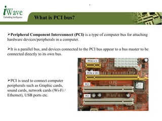
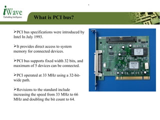
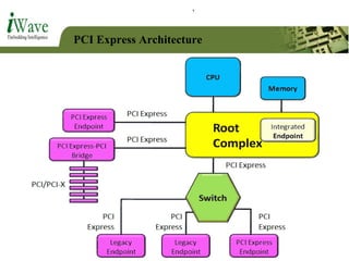
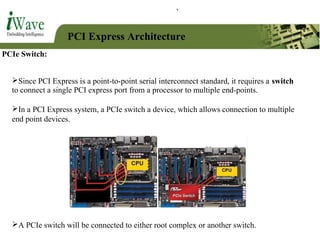
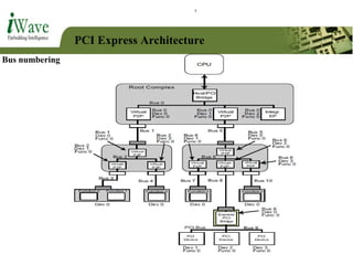
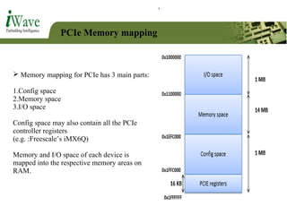
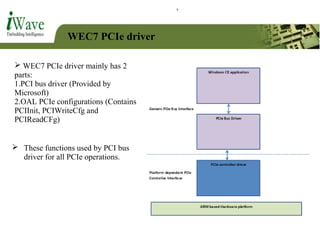
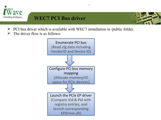
Keshava G N
Member – Technical (Software)
Topics
 Introduction: What is PCI bus?
 Introduction: What is PCI Express?
 Difference between PCI and PCI Express
 PCI Express: Architecture
 PCI Express: Hardware basics
 PCI Express: Configuration Space
 PCI Express: Memory mapping
 PCI Express: WEC7 driver basics
What is PCI bus?
Peripheral Component Interconnect (PCI) is a type of computer bus for attaching
hardware devices/peripherals in a computer.
It is a parallel bus, and devices connected to the PCI bus appear to a bus master to be
connected directly to its own bus.
PCI is used to connect computer
peripherals such as Graphic cards,
sound cards, network cards (Wi-Fi /
Ethernet), USB ports etc.
What is PCI bus?
PCI bus specifications were introduced by
Intel In July 1993.
It provides direct access to system
memory for connected devices.
PCI bus supports fixed width 32 bits, and
maximum of 5 devices can be connected.
PCI operated at 33 MHz using a 32-bit-
wide path.
Revisions to the standard include
increasing the speed from 33 MHz to 66
MHz and doubling the bit count to 64.
What is PCI bus?
PCI achieved popularity after the arrival of Windows 95 (in 1995).
This is due to the fact that Windows95 supported a feature called Plug and Play
(PnP).
Intel created the PnP standard and incorporated it into the design for PCI.
PCI-X:
PCI-X is extended version of PCI.
PCI-X provides for 64-bit transfers at a
speed of 133 MHz.
What is PCI Express?
PCI Express (Peripheral Component Interconnect Express), abbreviated as PCIe,
is a high-speed serial computer expansion bus standard designed to replace the older PCI
and PCI-X bus standards.
PCIe is having many improvements over the
older PCI/PCI-X such as:
Developed by Intel in 2004.
PCI Express is a serial interface, unlike PCI and PCI-X, which are parallel
interfaces.
Higher maximum system bus throughput, lower I/O pin count, smaller physical
footprint, better performance-scaling for bus devices, a more detailed error detection
and reporting mechanism (Advanced Error Reporting (AER)).
What are the differences between PCI
and PCI Express?
PCI PCI Express
Parallel Bus Serial Bus
Speed is 133MB/s to 533 MB/s Speed is 250 MB/s to several GB/s per
lane
Maximum of 5 End point devices can
be connected
Maximum of 32 devices can be
connected on each bus
Shared bus topology Point-to-point bus/
Shared switch topology
Hot plugging functionality is not
available
Hot plugging is supported
What are the differences between PCI
and PCI Express?
Difference in topology:
PCI : Parallel PCI Express: Serial
PCI Express Architecture
PCIe Root Complex:
In a PCI Express system, a root complex device connects the processor (and memory
subsystem) to the PCI Express End point devices or switch devices.
A root complex can be connected a maximum of 32 devices (Either end point device or
switch.)
The root complex generates transaction requests on behalf of the processor, which is
interconnected through a local bus.
Root complex functionality may be implemented as a discrete device, or may be
integrated with the processor.
PCI Express Architecture
PCIe End point device:
Endpoints are devices other than root complex and switches that are requesters or completers
of PCI Express transactions.
They are peripheral devices such as Ethernet, USB or graphics devices. Endpoints initiate
transactions as a requester or respond to transactions as a completer.
End point device will be connected to either root complex or switch.
Two types of endpoints exist, PCI Express (Native) endpoints and legacy
endpoints.
Some PCIe End point devices
Wi-Fi card Ethernet card Graphic card
USB ports
Audio card
PCI Express Architecture
PCIe Switch:
In a PCI Express system, a PCIe switch a device, which allows connection to multiple
end point devices.
Since PCI Express is a point-to-point serial interconnect standard, it requires a switch
to connect a single PCI express port from a processor to multiple end-points.
A PCIe switch will be connected to either root complex or another switch.
PCI Express Architecture
PCIe Bridges:
PCI Express bridges allow devices with other standards to be used in systems that need
to interoperate with PCI Express.
These bridges facilitate connection back to conventional PCI/PCI-X buses.
Applications using these bridge devices include servers, storage host bus adapters,
graphics, TV tuners and security systems.
PCI Express Architecture
Each end point device is identified by the combination of bus number, device number
and function number.
Function number:
PCI Express devices may support up to 8 functions per endpoint with at least one
function being number 0.
Device number:
Each bus can support up to 32 PCIe devices, which can be either switch or end point
device.
Bus number:
A system could theoretically include up to 256 buses. (Also called Links)
PCI Express Architecture
Bus numbering
PCI Express Architecture
A Port is the interface between a PCI Express component and the bus, and
consists of differential transmitters and receivers.
An Upstream Port is a port that points in the direction of the root complex.
A Downstream Port is a port that points away from the root complex.
An endpoint port is therefore, by definition, always an upstream port, and A
root complex port(s) is a downstream port.
PCI Express Lanes
The PCIe link between two devices can
consist of anywhere from 1 to 32 lanes.
These are differentiated as x1, x2, x4, x8,
x16 and x32 PCIe links (and PCIe
connectors).
Each lane consists on two pair of wires,
one pair for receiving data, and another for
transmitting.
Each lane carries data of 1 bit/cycle.
So, transfer rate increases as number of
lanes increases.
PCI Express Connectors (PCIe Slots)
PCIe slot can be of types: x1, x2, x4,
x8, x16 or x32.
A connector of type x1 can be
connected in x2 slot, but the reverse is
not possible.
PCIe Configuration space
 Software model of PCIe is same as older PCI/PCI-X.
 So there will be no difference in the bus driver software model.
 The PCI Express configuration model supports two mechanisms:
The PCI compatible configuration model, which is 100% compatible with old
PCI/PCI-X drivers and bus enumeration and configuration software for PCI/PCI-
X systems.
The PCI Express enhanced configuration mechanism which provides access to
additional configuration space beyond the first 256 Bytes, up to 4Kbytes per
function.
 Enhanced configuration
contains the data that are
additional features for PCIe.
E.g: Link training (Linkup
detection)
 Configuration space will be
according to PCIe v2.1.
Example is as shown:
PCIe Memory mapping
 Memory mapping for PCIe has 3 main parts:
1.Config space
2.Memory space
3.I/O space
Config space may also contain all the PCIe
controller registers
(e.g. :Freescale’s iMX6Q)
Memory and I/O space of each device is
mapped into the respective memory areas on
RAM.
WEC7 PCIe driver
 WEC7 PCIe driver mainly has 2
parts:
1.PCI bus driver (Provided by
Microsoft)
2.OAL PCIe configurations (Contains
PCIInit, PCIWriteCfg and
PCIReadCFg)
 These functions used by PCI bus
driver for all PCIe operations.
WEC7 PCI Bus driver
 PCI bus driver which is available with WEC7 installation in /public folder.
 The driver flow is as follows:
Enumerate PCI bus
(Read cfg data including
VendorID and Device ID)
Configure PCI bus memory
mapping
(Allocate memory/IO
space for PCIe devices)
Launch the PCIe EP driver
(Compare Vid & Pid with
registry entries, and
launch corresponding
EPDriver.dll)
THANK YOU

PCIe and PCIe driver in WEC7 (Windows Embedded compact 7)

  • 1.
    Keshava G N Member– Technical (Software)
  • 2.
    Topics  Introduction: Whatis PCI bus?  Introduction: What is PCI Express?  Difference between PCI and PCI Express  PCI Express: Architecture  PCI Express: Hardware basics  PCI Express: Configuration Space  PCI Express: Memory mapping  PCI Express: WEC7 driver basics
  • 3.
    What is PCIbus? Peripheral Component Interconnect (PCI) is a type of computer bus for attaching hardware devices/peripherals in a computer. It is a parallel bus, and devices connected to the PCI bus appear to a bus master to be connected directly to its own bus. PCI is used to connect computer peripherals such as Graphic cards, sound cards, network cards (Wi-Fi / Ethernet), USB ports etc.
  • 4.
    What is PCIbus? PCI bus specifications were introduced by Intel In July 1993. It provides direct access to system memory for connected devices. PCI bus supports fixed width 32 bits, and maximum of 5 devices can be connected. PCI operated at 33 MHz using a 32-bit- wide path. Revisions to the standard include increasing the speed from 33 MHz to 66 MHz and doubling the bit count to 64.
  • 5.
    What is PCIbus? PCI achieved popularity after the arrival of Windows 95 (in 1995). This is due to the fact that Windows95 supported a feature called Plug and Play (PnP). Intel created the PnP standard and incorporated it into the design for PCI. PCI-X: PCI-X is extended version of PCI. PCI-X provides for 64-bit transfers at a speed of 133 MHz.
  • 6.
    What is PCIExpress? PCI Express (Peripheral Component Interconnect Express), abbreviated as PCIe, is a high-speed serial computer expansion bus standard designed to replace the older PCI and PCI-X bus standards. PCIe is having many improvements over the older PCI/PCI-X such as: Developed by Intel in 2004. PCI Express is a serial interface, unlike PCI and PCI-X, which are parallel interfaces. Higher maximum system bus throughput, lower I/O pin count, smaller physical footprint, better performance-scaling for bus devices, a more detailed error detection and reporting mechanism (Advanced Error Reporting (AER)).
  • 7.
    What are thedifferences between PCI and PCI Express? PCI PCI Express Parallel Bus Serial Bus Speed is 133MB/s to 533 MB/s Speed is 250 MB/s to several GB/s per lane Maximum of 5 End point devices can be connected Maximum of 32 devices can be connected on each bus Shared bus topology Point-to-point bus/ Shared switch topology Hot plugging functionality is not available Hot plugging is supported
  • 8.
    What are thedifferences between PCI and PCI Express? Difference in topology: PCI : Parallel PCI Express: Serial
  • 9.
  • 10.
    PCI Express Architecture PCIeRoot Complex: In a PCI Express system, a root complex device connects the processor (and memory subsystem) to the PCI Express End point devices or switch devices. A root complex can be connected a maximum of 32 devices (Either end point device or switch.) The root complex generates transaction requests on behalf of the processor, which is interconnected through a local bus. Root complex functionality may be implemented as a discrete device, or may be integrated with the processor.
  • 11.
    PCI Express Architecture PCIeEnd point device: Endpoints are devices other than root complex and switches that are requesters or completers of PCI Express transactions. They are peripheral devices such as Ethernet, USB or graphics devices. Endpoints initiate transactions as a requester or respond to transactions as a completer. End point device will be connected to either root complex or switch. Two types of endpoints exist, PCI Express (Native) endpoints and legacy endpoints.
  • 12.
    Some PCIe Endpoint devices Wi-Fi card Ethernet card Graphic card USB ports Audio card
  • 13.
    PCI Express Architecture PCIeSwitch: In a PCI Express system, a PCIe switch a device, which allows connection to multiple end point devices. Since PCI Express is a point-to-point serial interconnect standard, it requires a switch to connect a single PCI express port from a processor to multiple end-points. A PCIe switch will be connected to either root complex or another switch.
  • 14.
    PCI Express Architecture PCIeBridges: PCI Express bridges allow devices with other standards to be used in systems that need to interoperate with PCI Express. These bridges facilitate connection back to conventional PCI/PCI-X buses. Applications using these bridge devices include servers, storage host bus adapters, graphics, TV tuners and security systems.
  • 15.
    PCI Express Architecture Eachend point device is identified by the combination of bus number, device number and function number. Function number: PCI Express devices may support up to 8 functions per endpoint with at least one function being number 0. Device number: Each bus can support up to 32 PCIe devices, which can be either switch or end point device. Bus number: A system could theoretically include up to 256 buses. (Also called Links)
  • 16.
  • 17.
    PCI Express Architecture APort is the interface between a PCI Express component and the bus, and consists of differential transmitters and receivers. An Upstream Port is a port that points in the direction of the root complex. A Downstream Port is a port that points away from the root complex. An endpoint port is therefore, by definition, always an upstream port, and A root complex port(s) is a downstream port.
  • 18.
    PCI Express Lanes ThePCIe link between two devices can consist of anywhere from 1 to 32 lanes. These are differentiated as x1, x2, x4, x8, x16 and x32 PCIe links (and PCIe connectors). Each lane consists on two pair of wires, one pair for receiving data, and another for transmitting. Each lane carries data of 1 bit/cycle. So, transfer rate increases as number of lanes increases.
  • 19.
    PCI Express Connectors(PCIe Slots) PCIe slot can be of types: x1, x2, x4, x8, x16 or x32. A connector of type x1 can be connected in x2 slot, but the reverse is not possible.
  • 20.
    PCIe Configuration space Software model of PCIe is same as older PCI/PCI-X.  So there will be no difference in the bus driver software model.  The PCI Express configuration model supports two mechanisms: The PCI compatible configuration model, which is 100% compatible with old PCI/PCI-X drivers and bus enumeration and configuration software for PCI/PCI- X systems. The PCI Express enhanced configuration mechanism which provides access to additional configuration space beyond the first 256 Bytes, up to 4Kbytes per function.  Enhanced configuration contains the data that are additional features for PCIe. E.g: Link training (Linkup detection)  Configuration space will be according to PCIe v2.1. Example is as shown:
  • 21.
    PCIe Memory mapping Memory mapping for PCIe has 3 main parts: 1.Config space 2.Memory space 3.I/O space Config space may also contain all the PCIe controller registers (e.g. :Freescale’s iMX6Q) Memory and I/O space of each device is mapped into the respective memory areas on RAM.
  • 22.
    WEC7 PCIe driver WEC7 PCIe driver mainly has 2 parts: 1.PCI bus driver (Provided by Microsoft) 2.OAL PCIe configurations (Contains PCIInit, PCIWriteCfg and PCIReadCFg)  These functions used by PCI bus driver for all PCIe operations.
  • 23.
    WEC7 PCI Busdriver  PCI bus driver which is available with WEC7 installation in /public folder.  The driver flow is as follows: Enumerate PCI bus (Read cfg data including VendorID and Device ID) Configure PCI bus memory mapping (Allocate memory/IO space for PCIe devices) Launch the PCIe EP driver (Compare Vid & Pid with registry entries, and launch corresponding EPDriver.dll)
  • 24.