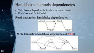
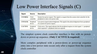
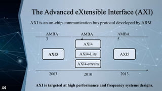
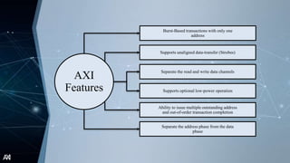
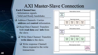
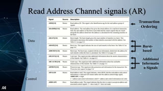
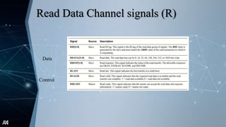
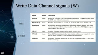
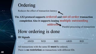
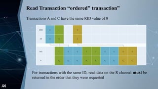
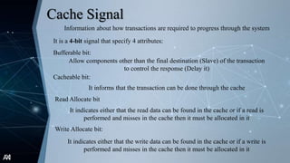
AMBAAXI Protocol
Advanced eXtensible Interface
AXI
Introduction
AXI
AMBA objectives for new interfaces
High-bandwidth and
low-latency
Backward-
compatible
Meet the
requirements for a
wide-range of
components
High-frequency
operation
Flexible
implementation of
interconnect
AXI
AMBA objectives for new interfaces
AXI
AXI
The Advanced eXtensible Interface (AXI)
AXI is an on-chip communication bus protocol developed by ARM
AXI is targeted at high performance and frequency systems designs.
AXI3
AXI4
AXI4-Lite
AXI4-stream
AXI5
AMBA
4
AMBA
3
AMBA
5
2003 2010 2013
AXI
AXI
Features
Burst-Based transactions with only one
address
Supports unaligned data-transfer (Strobes)
Supports optional low-power operation
Ability to issue multiple outstanding address
and out-of-order transaction completion
Separate the read and write data channels
Separate the address phase from the data
phase
AXI
Architecture
AXI
AXI Protocol system
AXI provides a single interface definitions for all the possible
connections of the system
Master 1 Master 2 Master 3
Slave 4
Slave 3
Slave 2
Slave 1
Interconnect
Interface
Interface
AXI
AXI Master-Slave Connection
Each Channel has:
- Information signals.
- Valid and Ready handshake.
 Address Channels: Carries
address and control information.
 Read Data Channel: Transfers
both read data and info from
the slave.
 Write Data Channel: Transfers
write data to the slave.
 Write response Channel:
Slave respond to the write
transactions
AXI
AXI Master-Slave Communication
• Write transaction can start with
address and control information or
the data
• Full Duplex Protocol !!
• Every Read transaction must start
with address and control
information on the address
channel.
However, the response must
come as the end of the
transaction
AXI
Signals
AXI
Read Address Channel signals (AR)
Data
Control
Transaction
Ordering
Burst-
based
Additional
Informatio
n Signals
AXI
Read Data Channel signals (R)
Data
Control
AXI
Write Address Channel signals (AW)
Data
Control
Transaction
Ordering
Burst-
based
Additional
Informatio
n Signals
AXI
Write Data Channel signals (W)
Data
Control
AXI
Write Response Channel signals (B)
Data
Control
AXI
Ordering Model
AXI
Ordering
The AXI protocol supports ordered and out-of-order transaction
completion Also it supports issuing multiple outstanding
addresses
Parallel processing of transactions
Reduces the effect of transaction latency
How ordering is done
ID Signals
AWID WID BID ARID RID
All transactions with the same ID must be ordered,
There is no restriction on transactions with different IDs
AXI
Read Transaction “Out-of-order
transaction”
Read operation for interleaved transactions A and B
The RID signal value differentiate which transaction the data relates to
AXI
Read Transaction “ordered” transaction”
Transactions A and C have the same RID value of 0
For transactions with the same ID, read data on the R channel must be
returned in the order that they were requested
AXI
Write Transaction “Out-of-order
transaction”
Transactions with different IDs can complete in any order
Note: In AXI4 the Write data on the W channel must follow the
same order as the address transfers on the AW channel
AXI4 Transaction
AXI
Write Transaction “ordered” transaction”
A manager can have multiple outstanding transactions with the same ID
Transactions A and C have the same ID, so they must complete in the same
order as they were issued: A first, then C
AXI4 Transaction
AXI
Addressing
Options
AXI
Addressing
 In most transactions the master begins each burst by driving the burst
control information and the address of the first byte in the transfer
 Bursts must not cross 4KB boundaries
Burst Length Burst Size Burst Type
Specifies the number
of transfers occurs
in each burst
Specifies the number
of bytes in each
transfer
4-bit signal
→ (16 transfer max)
3-bit signal
→ 2𝑠𝑖𝑧𝑒
bytes (128 max)
Determine the burst type:
- Fixed
- Incrementing
- Wrapping
2-bit signal
AXI
Calculating the Wrap Boundary
Startboundary =
Start Address
(No.Bytes)(Burst length)
(No. Bytes)(Burst length)
Example 0x 0
0x 4
0x 30
0x 34
0x 38
0x 3c
0x 40
0x
FF..F
0x 44
No. Bytes = 4
Burst length = 4
Start Address = 0x34
Wrapboundary = Startboundary + (No. Bytes)(Burst length)
Startboundary = 0x30
Wrapboundary = 0x40
AXI
Address Channels’
Information
Signals
AXI
Lock Signal
- Atomic Access
Information about the accessing type between masters and slaves
Locked Access Exclusive Access
Locked
Access:
Exclusive
Access:
Doesn’t restrict the accesses to the exclusive slave
but prevent the access to the memory region
Prevent other masters from
accessing the locked slave
Locked
Access
Master 1
Normal
Access
Master 2
AXI
Lock Signal
- Atomic Access
Information about the accessing type between masters and slaves
Locked Access Exclusive Access
Locked
Access:
Exclusive
Access:
Doesn’t restrict the accesses to the exclusive slave
but prevent the access to the memory region
Prevent other masters from
accessing the locked slave
Exclusive
Access
Master 1
Normal
Access
Master 2
AXI
Cache Signal
Information about how transactions are required to progress through the system
It is a 4-bit signal that specify 4 attributes:
Bufferable bit:
Cacheable bit:
Write Allocate bit:
Read Allocate bit
Allow components other than the final destination (Slave) of the transaction
to control the response (Delay it)
It informs that the transaction can be done through the cache
It indicates either that the read data can be found in the cache or if a read is
performed and misses in the cache then it must be allocated in it
It indicates either that the write data can be found in the cache or if a write is
performed and misses in the cache then it must be allocated in it
AXI
Protect Signal
Information about the level of access protection
PROT [2:0] Protection Level
bit[0]
1= privileged access
0 = normal access
bit[1]
1 = nonsecure access
0 = secure access
bit[2]
1 = instruction access
0 = data access
Protection encoding
AXI
Response
Signals
AXI
Response Signals
OKAY
Exclusive
OKAY
Slave
Error
Decode
Error
Normal Access
Success
Exclusive
Access Failure
Exclusive
Access Pass
Slave Error
after receiving
the transaction
Unsuccessful
transaction
Generated by the
Interconnect
Indicates slave
address error
AXI
Write Data Strobes
and Unaligned
transfers
AXI
Write strobes
The write data strobe signal is used by a master to tell a slave which
bytes of the data bus are required
The write channel has one strobe bit per byte on the data bus
0
1
2
3
S-2
S-1
0
7
8
15
16
23
N-8
N-1
∴ N: is the data-bus bits ∴S: is the strobe bit
AXI
Unaligned Addresses
AXI supports the unaligned start address
The master can simply provide an aligned address and rely on the byte
strobes to provide the information about which byte lanes the data is using
AXI
Handshake
Process
AXI
Valid-Ready Handshake
 The source generates the VALID signal to indicate when the data
or control information is available.
 The destination generates the READY signal to indicate that it
accepts the data.
 Transfer occurs only when both the VALID and READY signals
are HIGH.
All the five channels use the same VALID/READY
handshake to transfer data and control information.
AXI
Handshake Sequences
Valid before Ready
handshake
Ready before Valid
handshake
Valid with Ready handshake
AXI
Handshake channels dependencies
- Valid doesn’t depend on the Ready in the same channel
- Ready can wait for the Valid
Read transaction handshake dependencies
Write transaction handshake dependencies (AXI3)
AXI
Handshake channels dependencies
- Valid doesn’t depend on the Ready in the same channel
- Ready can wait for the Valid
Read transaction handshake dependencies
Write transaction handshake dependencies (AXI4)
AXI
Basic
Transaction
AXI
Read Burst Transaction
AXI
Overlapping Read Burst Transaction
AXI
Write Burst Transaction
AXI
Low Power
Interface
AXI
Low Power Interface Signals (C)
The simplest system clock controller interface is that with no power-
down or power-up sequence. (Only CACTIVE Is required)
More complex peripheral with a power-down or power-up sequence
entry into a low-power state occurs only after a request from the system
clock controller
AXI
Low Power Interface Signals (C)
The relationship between CSYSREQ and CSYSACK
The sequence of events when a peripheral accepts a system low-power
request.
AXI
Thank you

AXI Protocol.pptx

  • 1.
  • 2.
  • 3.
    AXI AMBA objectives fornew interfaces High-bandwidth and low-latency Backward- compatible Meet the requirements for a wide-range of components High-frequency operation Flexible implementation of interconnect
  • 4.
    AXI AMBA objectives fornew interfaces AXI
  • 5.
    AXI The Advanced eXtensibleInterface (AXI) AXI is an on-chip communication bus protocol developed by ARM AXI is targeted at high performance and frequency systems designs. AXI3 AXI4 AXI4-Lite AXI4-stream AXI5 AMBA 4 AMBA 3 AMBA 5 2003 2010 2013
  • 6.
    AXI AXI Features Burst-Based transactions withonly one address Supports unaligned data-transfer (Strobes) Supports optional low-power operation Ability to issue multiple outstanding address and out-of-order transaction completion Separate the read and write data channels Separate the address phase from the data phase
  • 7.
  • 8.
    AXI AXI Protocol system AXIprovides a single interface definitions for all the possible connections of the system Master 1 Master 2 Master 3 Slave 4 Slave 3 Slave 2 Slave 1 Interconnect Interface Interface
  • 9.
    AXI AXI Master-Slave Connection EachChannel has: - Information signals. - Valid and Ready handshake.  Address Channels: Carries address and control information.  Read Data Channel: Transfers both read data and info from the slave.  Write Data Channel: Transfers write data to the slave.  Write response Channel: Slave respond to the write transactions
  • 10.
    AXI AXI Master-Slave Communication •Write transaction can start with address and control information or the data • Full Duplex Protocol !! • Every Read transaction must start with address and control information on the address channel. However, the response must come as the end of the transaction
  • 11.
  • 12.
    AXI Read Address Channelsignals (AR) Data Control Transaction Ordering Burst- based Additional Informatio n Signals
  • 13.
    AXI Read Data Channelsignals (R) Data Control
  • 14.
    AXI Write Address Channelsignals (AW) Data Control Transaction Ordering Burst- based Additional Informatio n Signals
  • 15.
    AXI Write Data Channelsignals (W) Data Control
  • 16.
    AXI Write Response Channelsignals (B) Data Control
  • 17.
  • 18.
    AXI Ordering The AXI protocolsupports ordered and out-of-order transaction completion Also it supports issuing multiple outstanding addresses Parallel processing of transactions Reduces the effect of transaction latency How ordering is done ID Signals AWID WID BID ARID RID All transactions with the same ID must be ordered, There is no restriction on transactions with different IDs
  • 19.
    AXI Read Transaction “Out-of-order transaction” Readoperation for interleaved transactions A and B The RID signal value differentiate which transaction the data relates to
  • 20.
    AXI Read Transaction “ordered”transaction” Transactions A and C have the same RID value of 0 For transactions with the same ID, read data on the R channel must be returned in the order that they were requested
  • 21.
    AXI Write Transaction “Out-of-order transaction” Transactionswith different IDs can complete in any order Note: In AXI4 the Write data on the W channel must follow the same order as the address transfers on the AW channel AXI4 Transaction
  • 22.
    AXI Write Transaction “ordered”transaction” A manager can have multiple outstanding transactions with the same ID Transactions A and C have the same ID, so they must complete in the same order as they were issued: A first, then C AXI4 Transaction
  • 23.
  • 24.
    AXI Addressing  In mosttransactions the master begins each burst by driving the burst control information and the address of the first byte in the transfer  Bursts must not cross 4KB boundaries Burst Length Burst Size Burst Type Specifies the number of transfers occurs in each burst Specifies the number of bytes in each transfer 4-bit signal → (16 transfer max) 3-bit signal → 2𝑠𝑖𝑧𝑒 bytes (128 max) Determine the burst type: - Fixed - Incrementing - Wrapping 2-bit signal
  • 25.
    AXI Calculating the WrapBoundary Startboundary = Start Address (No.Bytes)(Burst length) (No. Bytes)(Burst length) Example 0x 0 0x 4 0x 30 0x 34 0x 38 0x 3c 0x 40 0x FF..F 0x 44 No. Bytes = 4 Burst length = 4 Start Address = 0x34 Wrapboundary = Startboundary + (No. Bytes)(Burst length) Startboundary = 0x30 Wrapboundary = 0x40
  • 26.
    AXI Calculating the WrapBoundary Startboundary = Start Address (No.Bytes)(Burst length) (No. Bytes)(Burst length) Example 0x 0 0x 4 0x 30 0x 34 0x 38 0x 3c 0x 40 0x FF..F 0x 44 No. Bytes = 4 Burst length = 4 Start Address = 0x34 Wrapboundary = Startboundary + (No. Bytes)(Burst length) Startboundary = 0x30 Wrapboundary = 0x40
  • 27.
  • 28.
    AXI Lock Signal - AtomicAccess Information about the accessing type between masters and slaves Locked Access Exclusive Access Locked Access: Exclusive Access: Doesn’t restrict the accesses to the exclusive slave but prevent the access to the memory region Prevent other masters from accessing the locked slave Locked Access Master 1 Normal Access Master 2
  • 29.
    AXI Lock Signal - AtomicAccess Information about the accessing type between masters and slaves Locked Access Exclusive Access Locked Access: Exclusive Access: Doesn’t restrict the accesses to the exclusive slave but prevent the access to the memory region Prevent other masters from accessing the locked slave Exclusive Access Master 1 Normal Access Master 2
  • 30.
    AXI Lock Signal - AtomicAccess Information about the accessing type between masters and slaves Locked Access Exclusive Access Locked Access: Exclusive Access: Doesn’t restrict the accesses to the exclusive slave but prevent the access to the memory region Prevent other masters from accessing the locked slave Exclusive Access Master 1 Normal Access Master 2
  • 31.
    AXI Cache Signal Information abouthow transactions are required to progress through the system It is a 4-bit signal that specify 4 attributes: Bufferable bit: Cacheable bit: Write Allocate bit: Read Allocate bit Allow components other than the final destination (Slave) of the transaction to control the response (Delay it) It informs that the transaction can be done through the cache It indicates either that the read data can be found in the cache or if a read is performed and misses in the cache then it must be allocated in it It indicates either that the write data can be found in the cache or if a write is performed and misses in the cache then it must be allocated in it
  • 32.
    AXI Protect Signal Information aboutthe level of access protection PROT [2:0] Protection Level bit[0] 1= privileged access 0 = normal access bit[1] 1 = nonsecure access 0 = secure access bit[2] 1 = instruction access 0 = data access Protection encoding
  • 33.
  • 34.
    AXI Response Signals OKAY Exclusive OKAY Slave Error Decode Error Normal Access Success Exclusive AccessFailure Exclusive Access Pass Slave Error after receiving the transaction Unsuccessful transaction Generated by the Interconnect Indicates slave address error
  • 35.
    AXI Write Data Strobes andUnaligned transfers
  • 36.
    AXI Write strobes The writedata strobe signal is used by a master to tell a slave which bytes of the data bus are required The write channel has one strobe bit per byte on the data bus 0 1 2 3 S-2 S-1 0 7 8 15 16 23 N-8 N-1 ∴ N: is the data-bus bits ∴S: is the strobe bit
  • 37.
    AXI Unaligned Addresses AXI supportsthe unaligned start address The master can simply provide an aligned address and rely on the byte strobes to provide the information about which byte lanes the data is using
  • 38.
  • 39.
    AXI Valid-Ready Handshake  Thesource generates the VALID signal to indicate when the data or control information is available.  The destination generates the READY signal to indicate that it accepts the data.  Transfer occurs only when both the VALID and READY signals are HIGH. All the five channels use the same VALID/READY handshake to transfer data and control information.
  • 40.
    AXI Handshake Sequences Valid beforeReady handshake Ready before Valid handshake Valid with Ready handshake
  • 41.
    AXI Handshake channels dependencies -Valid doesn’t depend on the Ready in the same channel - Ready can wait for the Valid Read transaction handshake dependencies Write transaction handshake dependencies (AXI3)
  • 42.
    AXI Handshake channels dependencies -Valid doesn’t depend on the Ready in the same channel - Ready can wait for the Valid Read transaction handshake dependencies Write transaction handshake dependencies (AXI4)
  • 43.
  • 44.
  • 45.
  • 46.
  • 47.
  • 48.
    AXI Low Power InterfaceSignals (C) The simplest system clock controller interface is that with no power- down or power-up sequence. (Only CACTIVE Is required) More complex peripheral with a power-down or power-up sequence entry into a low-power state occurs only after a request from the system clock controller
  • 49.
    AXI Low Power InterfaceSignals (C) The relationship between CSYSREQ and CSYSACK The sequence of events when a peripheral accepts a system low-power request.
  • 50.