Download as PDF, PPTX


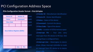
![Base Address Register (BAR)
Base Address Registers point to the location in the system address space
where the PCI device will be Mapped.The BAR essentially defines how much
memory space your device needs.
• The device RAM, etc. (anything really, per the vendor)
BARs are R/W and the BIOS programs them to set up the Memory Map
PCI Configuration Registers provides space for up to 6 BARs (bytes 10h thru
27h)
• BAR[0-5]
Each BAR is 32-bits wide to support 32-bit address space locations
Concatenating two 32-bit BARs provides 64-bit addressing capability
At boot time, the root complex probes the entire PCIE tree. It eventually
reaches our device, and attempts to Map all the BARs into its Device Memory
Map.](https://image.slidesharecdn.com/pciebasicsaif-170520162531/85/Pcie-basic-30-320.jpg)
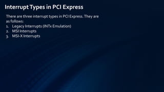


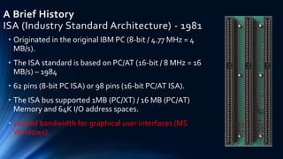
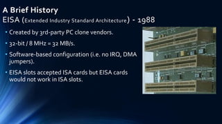
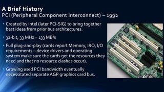
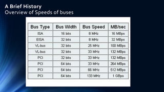
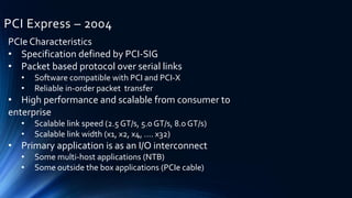
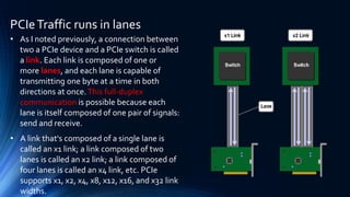
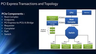
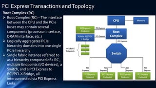
PCIe is a standard expansion card interface introduced in 2004 to replace PCI and PCI-X. It uses serial instead of parallel communication and is scalable, allowing for higher maximum system bandwidth. The presentation discusses the history of expansion card standards leading to PCIe, including ISA, EISA, VESA, PCI, and PCI-X. It also covers key aspects of PCIe such as the root complex, endpoints, switches, lanes, bus:device.function notation, enumeration, and address spaces such as configuration space.


