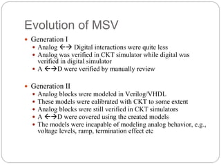
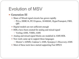
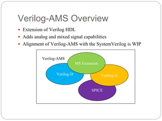
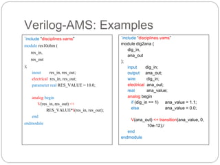
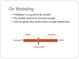
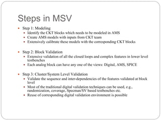
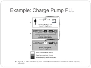
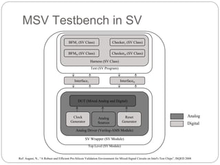
Sunil Kumar
Intel, Bangalore
Trends in Mixed Signal Validation
Agenda
Mixed Signal System
Evolution of MSV
Verilog-AMS Overview
Mixed Signal Tools
Steps in MSV
Conclusion
Mixed Signal System
A system having some parts in analog domain and
some in digital domain
A typical chip has these mixed signal blocks:
PLLs and
CLK dist.
Power
Distribution
Thermal
Sensors
Resets
High Speed Interconnect
BIAS
Gen/Comp
Sideband IOs
Mixed Signal System: An Example
Serializer
De-
serializer
Clock and
Data
Recovery
PLL PLL
BIAS
Generation
BIAS
Generation
Evolution of MSV
Generation I
Analog Digital interactions were quite less
Analog was verified in CKT simulator while digital was
verified in digital simulator
A D were verified by manually review
Generation II
Analog blocks were modeled in Verilog/VHDL
These models were calibrated with CKT to some extent
Analog blocks were still verified in CKT simulators
A D were covered using the created models
The models were incapable of modeling analog behavior, e.g.,
voltage levels, ramp, termination effect etc
Evolution of MSV
Generation III
Share of Mixed signal circuits has grown rapidly
PLLs, DDR3/4, PCI Express, 10/40GbE, HyperTransport, FBD,
QPI
Digital models are not sufficient enough
HDLs have been created for analog and mixed signal
Verilog-AMS, VHDL-AMS
Analog and mixed signal blocks are modeled in AMS HDL
New tools came up to support these languages
Mentor’s ADMS, Cadence’s AMS, Synopsys’s Discovery-AMS
Most of these tools have started supporting Fast SPICE
SPICE
Verilog-A
Verilog-AMS Overview
Extension of Verilog HDL
Adds analog and mixed signal capabilities
Alignment of Verilog-AMS with the SystemVerilog is WIP
Verilog-D
MS Extension
Verilog-AMS
Verilog-AMS: Examples
`include “disciplines.vams”
module res10ohm (
res_in,
res_out
);
inout res_in, res_out;
electrical res_in, res_out;
parameter real RES_VALUE = 10.0;
analog begin
V(res_in, res_out) <+
RES_VALUE*I(res_in, res_out);
end
endmodule
`include “disciplines.vams”
module dig2ana (
dig_in,
ana_out
);
input dig_in;
output ana_out;
wire dig_in;
electrical ana_out;
real ana_value;
analog begin
if (dig_in == 1) ana_value = 1.1;
else ana_value = 0.0;
V(ana_out) <+ transition(ana_value, 0,
10e-12);/
end
endmodule
On Modeling
Validation is as good as the models
The models need to be accurate enough
And for speed, they need to have enough abstractions
Verilog-AMS
Verilog/SV SPICE
AccuracySpeed
Mixed Signal Tools
Combine two different methods of simulation
Event-driven simulation as found in logic simulators
Continuous-time simulation as found in circuit simulators
Use digital simulator and analog simulator
Mentor’s ADMS : Modelsim + Eldo
Synopsys’s Discovery-AMS: VCS + Nanosim
Cadence’s AMS: NC-Sim + Spectre
On top of these the tool has to
Split the netlist in Verilog and SPICE and insertion of connect
modules
Set up and run the simulation by synchronizing the time steps of
two simulators
Steps in MSV
Step 1: Modeling
Identify the CKT blocks which needs to be modeled in AMS
Create AMS models with inputs from CKT team
Extensively calibrate these models with the corresponding CKT blocks
Step 2: Block Validation
Extensive validation of all the closed loops and complex features in lower level
testbenches
Each analog block can have any one of the views: Digital, AMS, SPICE
Step 3: Cluster/System Level Validation
Validate the sequence and inter-dependencies of the features validated at block
level
Most of the traditional digital validation techniques can be used, e.g.,
randomization, coverage, Specman/SV based testbenches etc.
Reuse of corresponding digital validation environment is possible
Example: Charge Pump PLL
Ref: August, N., “A Robust and Efficient Pre-Silicon Validation Environment for Mixed-Signal Circuits on Intel's Test Chips”,
ISQED 2008
Analog Driver (Verilog-AMS Module)
Test (SV Program)
Harness (SV Class)
MSV Testbench in SV
BFM1 (SV Class)
BFMN (SV Class)
Checker1 (SV Class)
CheckerN (SV Class)
Interface1 InterfaceN
DUT (Mixed Analog and Digital)
Clock
Generator
Analog
Sources
Reset
Generator
SV Wrapper (SV Module)
Top Level (SV Module)
Ref: August, N., “A Robust and Efficient Pre-Silicon Validation Environment for Mixed-Signal Circuits on Intel's Test Chips”, ISQED 2008
Analog
Digital
Conclusions
Mixed Signal Validation has become an important component of
the validation space
The MSV tools have matured
Many fatal bugs which were earlier found only in post-silicon
can be uncovered in MSV
Most of the digital validation techniques can be used
References
Verilog-AMS Language Reference Manual
http://www.verilog.org/verilog-ams/htmlpages/public-
docs/lrm/2.3/VAMS-LRM-2-3.pdf
“The Designer’s Guide to Verilog-AMS”, Kenneth S.
Kundert and Olaf Zinke, Springer, 2004
Verilog-AMS models examples:
http://www.designers-guide.org/VerilogAMS/
Q&A

Trends in Mixed Signal Validation

  • 1.
    Sunil Kumar Intel, Bangalore Trendsin Mixed Signal Validation
  • 2.
    Agenda Mixed Signal System Evolutionof MSV Verilog-AMS Overview Mixed Signal Tools Steps in MSV Conclusion
  • 3.
    Mixed Signal System Asystem having some parts in analog domain and some in digital domain A typical chip has these mixed signal blocks: PLLs and CLK dist. Power Distribution Thermal Sensors Resets High Speed Interconnect BIAS Gen/Comp Sideband IOs
  • 4.
    Mixed Signal System:An Example Serializer De- serializer Clock and Data Recovery PLL PLL BIAS Generation BIAS Generation
  • 5.
    Evolution of MSV GenerationI Analog Digital interactions were quite less Analog was verified in CKT simulator while digital was verified in digital simulator A D were verified by manually review Generation II Analog blocks were modeled in Verilog/VHDL These models were calibrated with CKT to some extent Analog blocks were still verified in CKT simulators A D were covered using the created models The models were incapable of modeling analog behavior, e.g., voltage levels, ramp, termination effect etc
  • 6.
    Evolution of MSV GenerationIII Share of Mixed signal circuits has grown rapidly PLLs, DDR3/4, PCI Express, 10/40GbE, HyperTransport, FBD, QPI Digital models are not sufficient enough HDLs have been created for analog and mixed signal Verilog-AMS, VHDL-AMS Analog and mixed signal blocks are modeled in AMS HDL New tools came up to support these languages Mentor’s ADMS, Cadence’s AMS, Synopsys’s Discovery-AMS Most of these tools have started supporting Fast SPICE
  • 7.
    SPICE Verilog-A Verilog-AMS Overview Extension ofVerilog HDL Adds analog and mixed signal capabilities Alignment of Verilog-AMS with the SystemVerilog is WIP Verilog-D MS Extension Verilog-AMS
  • 8.
    Verilog-AMS: Examples `include “disciplines.vams” moduleres10ohm ( res_in, res_out ); inout res_in, res_out; electrical res_in, res_out; parameter real RES_VALUE = 10.0; analog begin V(res_in, res_out) <+ RES_VALUE*I(res_in, res_out); end endmodule `include “disciplines.vams” module dig2ana ( dig_in, ana_out ); input dig_in; output ana_out; wire dig_in; electrical ana_out; real ana_value; analog begin if (dig_in == 1) ana_value = 1.1; else ana_value = 0.0; V(ana_out) <+ transition(ana_value, 0, 10e-12);/ end endmodule
  • 9.
    On Modeling Validation isas good as the models The models need to be accurate enough And for speed, they need to have enough abstractions Verilog-AMS Verilog/SV SPICE AccuracySpeed
  • 10.
    Mixed Signal Tools Combinetwo different methods of simulation Event-driven simulation as found in logic simulators Continuous-time simulation as found in circuit simulators Use digital simulator and analog simulator Mentor’s ADMS : Modelsim + Eldo Synopsys’s Discovery-AMS: VCS + Nanosim Cadence’s AMS: NC-Sim + Spectre On top of these the tool has to Split the netlist in Verilog and SPICE and insertion of connect modules Set up and run the simulation by synchronizing the time steps of two simulators
  • 11.
    Steps in MSV Step1: Modeling Identify the CKT blocks which needs to be modeled in AMS Create AMS models with inputs from CKT team Extensively calibrate these models with the corresponding CKT blocks Step 2: Block Validation Extensive validation of all the closed loops and complex features in lower level testbenches Each analog block can have any one of the views: Digital, AMS, SPICE Step 3: Cluster/System Level Validation Validate the sequence and inter-dependencies of the features validated at block level Most of the traditional digital validation techniques can be used, e.g., randomization, coverage, Specman/SV based testbenches etc. Reuse of corresponding digital validation environment is possible
  • 12.
    Example: Charge PumpPLL Ref: August, N., “A Robust and Efficient Pre-Silicon Validation Environment for Mixed-Signal Circuits on Intel's Test Chips”, ISQED 2008
  • 13.
    Analog Driver (Verilog-AMSModule) Test (SV Program) Harness (SV Class) MSV Testbench in SV BFM1 (SV Class) BFMN (SV Class) Checker1 (SV Class) CheckerN (SV Class) Interface1 InterfaceN DUT (Mixed Analog and Digital) Clock Generator Analog Sources Reset Generator SV Wrapper (SV Module) Top Level (SV Module) Ref: August, N., “A Robust and Efficient Pre-Silicon Validation Environment for Mixed-Signal Circuits on Intel's Test Chips”, ISQED 2008 Analog Digital
  • 14.
    Conclusions Mixed Signal Validationhas become an important component of the validation space The MSV tools have matured Many fatal bugs which were earlier found only in post-silicon can be uncovered in MSV Most of the digital validation techniques can be used
  • 15.
    References Verilog-AMS Language ReferenceManual http://www.verilog.org/verilog-ams/htmlpages/public- docs/lrm/2.3/VAMS-LRM-2-3.pdf “The Designer’s Guide to Verilog-AMS”, Kenneth S. Kundert and Olaf Zinke, Springer, 2004 Verilog-AMS models examples: http://www.designers-guide.org/VerilogAMS/
  • 16.