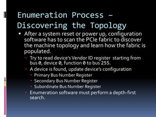
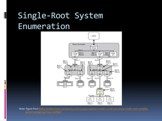
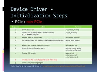
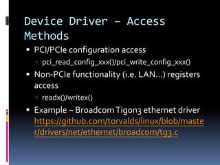
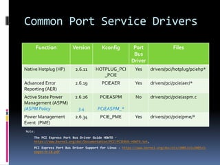
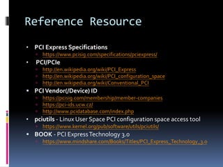
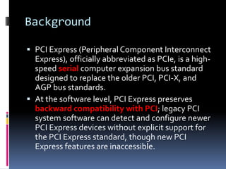
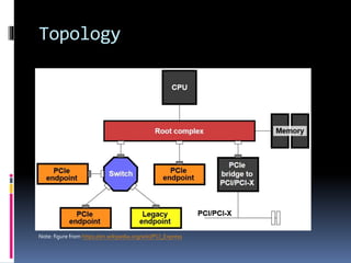
LINUX PCI EXPRESS DRIVER
Background
 PCI Express (Peripheral Component Interconnect
Express), officially abbreviated as PCIe, is a high-
speed serial computer expansion bus standard
designed to replace the older PCI, PCI-X, and
AGP bus standards.
 At the software level, PCI Express preserves
backward compatibility with PCI; legacy PCI
system software can detect and configure newer
PCI Express devices without explicit support for
the PCI Express standard, though new PCI
Express features are inaccessible.
Topology
Note: figure from https://en.wikipedia.org/wiki/PCI_Express
Terminology
 Lane
 A lane is composed of two differential signaling pairs, with one pair for receiving data and the other for
transmitting. 1, 2, …, 32 lanes will denote x1, x2, …, x32.
 Root Complex
 the device that connects the CPU and memory subsystem to the PCI Express fabric. It may support one or
more PCI Express ports.
 Endpoint
 devices other than root complex and switches that are requesters or completers of PCI Express transactions.
 Configuration Space
 PCI devices have a set of registers referred to as configuration space and PCI Express introduces extended
configuration space for devices.
 BAR
 Base Address Registers (commonly called BARs) to inform the device of its address mapping by writing
configuration commands to the PCI controller.
 INTx
 An in-band messages which emulate the four physical interrupt signals (INTA-INTD) routed between PCI
devices and the system interrupt controller
 MSI/MIS-X
 An alternative in-band method of signaling an interrupt, using special in-band messages to replace traditional
out-of-band assertion of dedicated interrupt lines.
Configuration Space Layout
Note: figure from
http://www.flashmemorysummit.com/English/Collaterals/Proceedings/2013/20130812_PreConfD_Onufryk.pdf
Configuration Space Header
Status
BIST
Header
Type
Latency
Timer
Cache
Line Size
Class Code
Rev
ID
Device ID Vendor ID
Command
Base Address 0 (BAR0)
Base Address 1 (BAR1)
Base Address 2 (BAR2)
Base Address 3 (BAR3)
Base Address 4 (BAR4)
Base Address 5 (BAR5)
CardBus CIS Pointer
Subsystem
Device ID
Subsystem
Vendor ID
Expansion ROM Base Address
Reserved
Capability
Pointer
Reserved
Max Lat Min Gnt
Interrupt
Pin
Interrupt
Line
00h
04h
08h
0Ch
10h
14h
18h
1Ch
20h
24h
28h
2Ch
30h
38h
34h
3Ch
07152331
Status
BIST
Header
Type
Latency
Timer
Cache
Line Size
Class Code
Rev
ID
Device ID Vendor ID
Command
Base Address 0 (BAR0)
Base Address 1 (BAR1)
Secondary
Lat timer
Secondary
Status
(Non-Prefetchable)
Memory Limit
Prefetchable
Memory Limit
Pretetchable Memory Base
Upper 32 Bits
Prefetchable Memory Limit
Upper 32 Bits
IO Limit
Upper 16 Bits
Reserved
Capability
Pointer
Expansion ROM Base Address
Max Lat Min Gnt
Interrupt
Pin
Interrupt
Line
00h
04h
08h
0Ch
10h
14h
18h
1Ch
20h
24h
28h
2Ch
30h
38h
34h
3Ch
07152331
Type 0 Header Type 1 Header
Subordinate
Bus #
Secondary
Bus #
Primary
Bus #
IO
Limit
IO
Base
(Non-Prefetchable)
Memory Base
Prefetchable
Memory Base
IO Base
Upper 16 Bits
Capabilities List
Example: http://www.alterawiki.com/wiki/PCI_Configuration_Space
Device Layers and their
Associated Packets
Note: figure from http://resources.infosecinstitute.com/system-address-map-initialization-x86x64-architecture-part-2-
pci-express-based-systems/
Layer Packets Relationship
Note: figure from http://www.verien.com/pcie_primer.htm
Function of Each PCIE Layer
 Transaction Layer
 Mechanisms for differentiating the ordering and processing
requirements ofTransaction Layer Packets (TLPs)
 Credit-based flow control
 TLP construction and processing
 Association of transaction-level mechanisms with device resources
including Flow Control andVirtual Channel management.
 Data Link Layer
 Data Exchange
 Error Detection and Retry
 Initialization and power management
 Physical Layer
 Logical Sub-block – symbol encoding, framing, data scrambling, Link
initialization and training, Lane to lane de-skew
 Electrical Sub-block – defines the physical layer of PCI Express that
consists of a reference clock source,Transmitter, channel, and Receiver.
Packet Routing
 Address Routing - Memory and IO requests
 Address routing is used to transfer data to or from
memory, memory mapped IO, or IO locations.
 ID Routing - Completions and Configuration
 ID routing is based on the logical position (Bus
Number, Device Number, Function Number) of a
device function within the PCI bus topology.
 Implicit Routing - Message requests
 Implicit routing is based on the intrinsic knowledge
PCI Express devices are required to have concerning
upstream and downstream traffic and the existence of
a single PCI Express Root Complex at the top of the
PCI Express topology.
pciutils – lspci command
 Command “lspci”
 is a utility for displaying information about PCI
buses in the system and devices connected to
them
 Command “lspci” popular options
 -t Show bus tree
 -v Be verbose (-vv for very verbose)
 -k Show kernel drivers handling each device
 -x Show hex-dump of the standard part of the config space
pciutils – lspci example
lspci -vkx
02:00.0 Ethernet controller: Broadcom Corporation NetXtreme BCM5720 Gigabit
Ethernet PCIe
Subsystem: Broadcom Corporation Device 2003
Flags: bus master, fast devsel, latency 0, IRQ 16
Memory at f0050000 (64-bit, prefetchable) [size=64K]
Memory at f0040000 (64-bit, prefetchable) [size=64K]
Memory at f0030000 (64-bit, prefetchable) [size=64K]
Expansion ROM at f7c40000 [disabled] [size=256K]
Capabilities: [48] Power Management version 3
Capabilities: [50] Vital Product Data
Capabilities: [58] MSI: Enable- Count=1/8 Maskable- 64bit+
Capabilities: [a0] MSI-X: Enable- Count=17 Masked-
Capabilities: [ac] Express Endpoint, MSI 00
Capabilities: [100] Advanced Error Reporting
Capabilities: [13c] Device Serial Number 00-00-00-0a-f7-82-bf-82
Capabilities: [150] Power Budgeting <?>
Capabilities: [160] Virtual Channel
Kernel driver in use: tg3
00: e4 14 5f 16 06 00 10 00 00 00 00 02 10 00 80 00
10: 0c 00 05 f0 00 00 00 00 0c 00 04 f0 00 00 00 00
20: 0c 00 03 f0 00 00 00 00 00 00 00 00 e4 14 03 20
30: 00 00 c4 f7 48 00 00 00 00 00 00 00 0b 01 00 00
Controller Driver
 Find and assign resource
 Controller registers
 BARs for devices (device tree format -
http://devicetree.org/Device_Tree_Usage#PCI_Address_Translation)
 Operation implementation
 PCIe configuration access
 struct pci_ops (defined in include/linux/pci.h)
 INTx interrupts
 struct irq_domain_ops (defined in include/linux/irqdomain.h)
 struct irq_chip (defined in include/linux/irq.h)
 MSI/MSI-X interrupts
 struct irq_domain_ops
 struct irq_chip
 Example – PCIe host controller driver for Samsung EXYNOS SoCs
https://github.com/torvalds/linux/blob/master/drivers/pci/host/pc
i-exynos.c + pcie-designware.c
Enumeration Process –
Discovering the Topology
 After a system reset or power up, configuration
software has to scan the PCIe fabric to discover
the machine topology and learn how the fabric is
populated.
 Try to read device’sVendor ID register starting from
bus 0, device 0, function 0 to bus 255.
 A device is found, update device’s configuration
 Primary Bus Number Register
 Secondary Bus Number Register
 Subordinate Bus Number Register
 Enumeration software must perform a depth-first
search.
Single-Root System
Enumeration
Note: figure from https://codywu2010.wordpress.com/2015/11/29/how-modern-multi-processor-multi-root-complex-
system-assigns-pci-bus-number/
Device Driver -
Initialization Steps
Sequence Action Function
1 Enable the device pci_enable_device()
2 Enable DMA by setting the bus master bit in the
PCI_COMMAND register
pci_set_master()
3 Request MMIO/IOP resources pci_request_region()
4 Set the DMA mask size (for both coherent and streaming DMA) pci_set_dma_mask()
5 Allocate and initialize shared control data pci_ioremap_bar()
6 Access device configuration space pci_read_config_xxx()/
pci_write_config_xxx()
7 Register IRQ handler request_irq()
pci_enable_msi()
pci_enable_msix()
8 Initialize non-PCI (i.e. LAN/SCSI/etc parts of the chip)
9 Enable DMA/processing engines
 PCIe + non-PCIe
Note: How To Write Linux PCI Drivers - https://www.kernel.org/doc/Documentation/PCI/pci.txt
Device Driver – Access
Methods
 PCI/PCIe configuration access
 pci_read_config_xxx()/pci_write_config_xxx()
 Non-PCIe functionality (i.e. LAN…) registers
access
 readx()/writex()
 Example – BroadcomTigon3 ethernet driver
https://github.com/torvalds/linux/blob/maste
r/drivers/net/ethernet/broadcom/tg3.c
Common Port Service Drivers
Function Version Kconfig Port
Bus
Driver
Files
Native Hotplug (HP) 2.6.11 HOTPLUG_PCI
_PCIE
Yes drivers/pci/hotplug/pciehp*
Advanced Error
Reporting (AER)
2.6.19 PCIEAER Yes drivers/pci/pcie/aer/*
Active State Power
Management (ASPM)
/ASPM Policy
2.6.26
3.4
PCIEASPM
PCIEASPM_*
No drivers/pci/pcie/aspm.c
Power Management
Event (PME)
2.6.34 PCIE_PME Yes drivers/pci/pcie/pme/*
Note:
The PCI Express Port Bus Driver Guide HOWTO -
https://www.kernel.org/doc/Documentation/PCI/PCIEBUS-HOWTO.txt,
PCI Express Port Bus Driver Support for Linux - https://www.kernel.org/doc/ols/2005/ols2005v2-
pages-9-18.pdf
Reference Resource
• PCI Express Specifications
 https://www.pcisig.com/specifications/pciexpress/
• PCI/PCIe
 http://en.wikipedia.org/wiki/PCI_Express
 http://en.wikipedia.org/wiki/PCI_configuration_space
 http://en.wikipedia.org/wiki/Conventional_PCI
 PCIVendor(/Device) ID
 https://pcisig.com/membership/member-companies
 https://pci-ids.ucw.cz/
 http://www.pcidatabase.com/index.php
• pciutils - Linux User Space PCI configuration space access tool
 https://www.kernel.org/pub/software/utils/pciutils/
 BOOK - PCI ExpressTechnology 3.0
 https://www.mindshare.com/Books/Titles/PCI_Express_Technology_3.0

Slideshare - PCIe

  • 1.
  • 2.
    Background  PCI Express(Peripheral Component Interconnect Express), officially abbreviated as PCIe, is a high- speed serial computer expansion bus standard designed to replace the older PCI, PCI-X, and AGP bus standards.  At the software level, PCI Express preserves backward compatibility with PCI; legacy PCI system software can detect and configure newer PCI Express devices without explicit support for the PCI Express standard, though new PCI Express features are inaccessible.
  • 3.
    Topology Note: figure fromhttps://en.wikipedia.org/wiki/PCI_Express
  • 4.
    Terminology  Lane  Alane is composed of two differential signaling pairs, with one pair for receiving data and the other for transmitting. 1, 2, …, 32 lanes will denote x1, x2, …, x32.  Root Complex  the device that connects the CPU and memory subsystem to the PCI Express fabric. It may support one or more PCI Express ports.  Endpoint  devices other than root complex and switches that are requesters or completers of PCI Express transactions.  Configuration Space  PCI devices have a set of registers referred to as configuration space and PCI Express introduces extended configuration space for devices.  BAR  Base Address Registers (commonly called BARs) to inform the device of its address mapping by writing configuration commands to the PCI controller.  INTx  An in-band messages which emulate the four physical interrupt signals (INTA-INTD) routed between PCI devices and the system interrupt controller  MSI/MIS-X  An alternative in-band method of signaling an interrupt, using special in-band messages to replace traditional out-of-band assertion of dedicated interrupt lines.
  • 5.
    Configuration Space Layout Note:figure from http://www.flashmemorysummit.com/English/Collaterals/Proceedings/2013/20130812_PreConfD_Onufryk.pdf
  • 6.
    Configuration Space Header Status BIST Header Type Latency Timer Cache LineSize Class Code Rev ID Device ID Vendor ID Command Base Address 0 (BAR0) Base Address 1 (BAR1) Base Address 2 (BAR2) Base Address 3 (BAR3) Base Address 4 (BAR4) Base Address 5 (BAR5) CardBus CIS Pointer Subsystem Device ID Subsystem Vendor ID Expansion ROM Base Address Reserved Capability Pointer Reserved Max Lat Min Gnt Interrupt Pin Interrupt Line 00h 04h 08h 0Ch 10h 14h 18h 1Ch 20h 24h 28h 2Ch 30h 38h 34h 3Ch 07152331 Status BIST Header Type Latency Timer Cache Line Size Class Code Rev ID Device ID Vendor ID Command Base Address 0 (BAR0) Base Address 1 (BAR1) Secondary Lat timer Secondary Status (Non-Prefetchable) Memory Limit Prefetchable Memory Limit Pretetchable Memory Base Upper 32 Bits Prefetchable Memory Limit Upper 32 Bits IO Limit Upper 16 Bits Reserved Capability Pointer Expansion ROM Base Address Max Lat Min Gnt Interrupt Pin Interrupt Line 00h 04h 08h 0Ch 10h 14h 18h 1Ch 20h 24h 28h 2Ch 30h 38h 34h 3Ch 07152331 Type 0 Header Type 1 Header Subordinate Bus # Secondary Bus # Primary Bus # IO Limit IO Base (Non-Prefetchable) Memory Base Prefetchable Memory Base IO Base Upper 16 Bits
  • 7.
  • 8.
    Device Layers andtheir Associated Packets Note: figure from http://resources.infosecinstitute.com/system-address-map-initialization-x86x64-architecture-part-2- pci-express-based-systems/
  • 9.
    Layer Packets Relationship Note:figure from http://www.verien.com/pcie_primer.htm
  • 10.
    Function of EachPCIE Layer  Transaction Layer  Mechanisms for differentiating the ordering and processing requirements ofTransaction Layer Packets (TLPs)  Credit-based flow control  TLP construction and processing  Association of transaction-level mechanisms with device resources including Flow Control andVirtual Channel management.  Data Link Layer  Data Exchange  Error Detection and Retry  Initialization and power management  Physical Layer  Logical Sub-block – symbol encoding, framing, data scrambling, Link initialization and training, Lane to lane de-skew  Electrical Sub-block – defines the physical layer of PCI Express that consists of a reference clock source,Transmitter, channel, and Receiver.
  • 11.
    Packet Routing  AddressRouting - Memory and IO requests  Address routing is used to transfer data to or from memory, memory mapped IO, or IO locations.  ID Routing - Completions and Configuration  ID routing is based on the logical position (Bus Number, Device Number, Function Number) of a device function within the PCI bus topology.  Implicit Routing - Message requests  Implicit routing is based on the intrinsic knowledge PCI Express devices are required to have concerning upstream and downstream traffic and the existence of a single PCI Express Root Complex at the top of the PCI Express topology.
  • 12.
    pciutils – lspcicommand  Command “lspci”  is a utility for displaying information about PCI buses in the system and devices connected to them  Command “lspci” popular options  -t Show bus tree  -v Be verbose (-vv for very verbose)  -k Show kernel drivers handling each device  -x Show hex-dump of the standard part of the config space
  • 13.
    pciutils – lspciexample lspci -vkx 02:00.0 Ethernet controller: Broadcom Corporation NetXtreme BCM5720 Gigabit Ethernet PCIe Subsystem: Broadcom Corporation Device 2003 Flags: bus master, fast devsel, latency 0, IRQ 16 Memory at f0050000 (64-bit, prefetchable) [size=64K] Memory at f0040000 (64-bit, prefetchable) [size=64K] Memory at f0030000 (64-bit, prefetchable) [size=64K] Expansion ROM at f7c40000 [disabled] [size=256K] Capabilities: [48] Power Management version 3 Capabilities: [50] Vital Product Data Capabilities: [58] MSI: Enable- Count=1/8 Maskable- 64bit+ Capabilities: [a0] MSI-X: Enable- Count=17 Masked- Capabilities: [ac] Express Endpoint, MSI 00 Capabilities: [100] Advanced Error Reporting Capabilities: [13c] Device Serial Number 00-00-00-0a-f7-82-bf-82 Capabilities: [150] Power Budgeting <?> Capabilities: [160] Virtual Channel Kernel driver in use: tg3 00: e4 14 5f 16 06 00 10 00 00 00 00 02 10 00 80 00 10: 0c 00 05 f0 00 00 00 00 0c 00 04 f0 00 00 00 00 20: 0c 00 03 f0 00 00 00 00 00 00 00 00 e4 14 03 20 30: 00 00 c4 f7 48 00 00 00 00 00 00 00 0b 01 00 00
  • 14.
    Controller Driver  Findand assign resource  Controller registers  BARs for devices (device tree format - http://devicetree.org/Device_Tree_Usage#PCI_Address_Translation)  Operation implementation  PCIe configuration access  struct pci_ops (defined in include/linux/pci.h)  INTx interrupts  struct irq_domain_ops (defined in include/linux/irqdomain.h)  struct irq_chip (defined in include/linux/irq.h)  MSI/MSI-X interrupts  struct irq_domain_ops  struct irq_chip  Example – PCIe host controller driver for Samsung EXYNOS SoCs https://github.com/torvalds/linux/blob/master/drivers/pci/host/pc i-exynos.c + pcie-designware.c
  • 15.
    Enumeration Process – Discoveringthe Topology  After a system reset or power up, configuration software has to scan the PCIe fabric to discover the machine topology and learn how the fabric is populated.  Try to read device’sVendor ID register starting from bus 0, device 0, function 0 to bus 255.  A device is found, update device’s configuration  Primary Bus Number Register  Secondary Bus Number Register  Subordinate Bus Number Register  Enumeration software must perform a depth-first search.
  • 16.
    Single-Root System Enumeration Note: figurefrom https://codywu2010.wordpress.com/2015/11/29/how-modern-multi-processor-multi-root-complex- system-assigns-pci-bus-number/
  • 17.
    Device Driver - InitializationSteps Sequence Action Function 1 Enable the device pci_enable_device() 2 Enable DMA by setting the bus master bit in the PCI_COMMAND register pci_set_master() 3 Request MMIO/IOP resources pci_request_region() 4 Set the DMA mask size (for both coherent and streaming DMA) pci_set_dma_mask() 5 Allocate and initialize shared control data pci_ioremap_bar() 6 Access device configuration space pci_read_config_xxx()/ pci_write_config_xxx() 7 Register IRQ handler request_irq() pci_enable_msi() pci_enable_msix() 8 Initialize non-PCI (i.e. LAN/SCSI/etc parts of the chip) 9 Enable DMA/processing engines  PCIe + non-PCIe Note: How To Write Linux PCI Drivers - https://www.kernel.org/doc/Documentation/PCI/pci.txt
  • 18.
    Device Driver –Access Methods  PCI/PCIe configuration access  pci_read_config_xxx()/pci_write_config_xxx()  Non-PCIe functionality (i.e. LAN…) registers access  readx()/writex()  Example – BroadcomTigon3 ethernet driver https://github.com/torvalds/linux/blob/maste r/drivers/net/ethernet/broadcom/tg3.c
  • 19.
    Common Port ServiceDrivers Function Version Kconfig Port Bus Driver Files Native Hotplug (HP) 2.6.11 HOTPLUG_PCI _PCIE Yes drivers/pci/hotplug/pciehp* Advanced Error Reporting (AER) 2.6.19 PCIEAER Yes drivers/pci/pcie/aer/* Active State Power Management (ASPM) /ASPM Policy 2.6.26 3.4 PCIEASPM PCIEASPM_* No drivers/pci/pcie/aspm.c Power Management Event (PME) 2.6.34 PCIE_PME Yes drivers/pci/pcie/pme/* Note: The PCI Express Port Bus Driver Guide HOWTO - https://www.kernel.org/doc/Documentation/PCI/PCIEBUS-HOWTO.txt, PCI Express Port Bus Driver Support for Linux - https://www.kernel.org/doc/ols/2005/ols2005v2- pages-9-18.pdf
  • 20.
    Reference Resource • PCIExpress Specifications  https://www.pcisig.com/specifications/pciexpress/ • PCI/PCIe  http://en.wikipedia.org/wiki/PCI_Express  http://en.wikipedia.org/wiki/PCI_configuration_space  http://en.wikipedia.org/wiki/Conventional_PCI  PCIVendor(/Device) ID  https://pcisig.com/membership/member-companies  https://pci-ids.ucw.cz/  http://www.pcidatabase.com/index.php • pciutils - Linux User Space PCI configuration space access tool  https://www.kernel.org/pub/software/utils/pciutils/  BOOK - PCI ExpressTechnology 3.0  https://www.mindshare.com/Books/Titles/PCI_Express_Technology_3.0

Editor's Notes

  • #4 https://en.wikipedia.org/wiki/PCI_Express
  • #10 http://www.verien.com/pcie_primer.htm
  • #11 http://www.testbench.in/introduction_to_pci_express.html