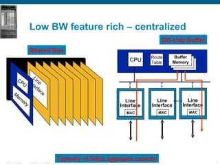
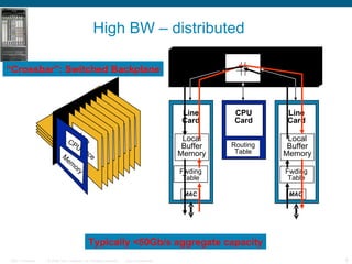
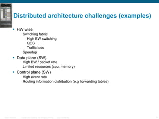
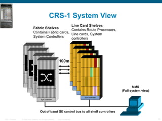
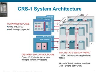
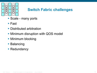
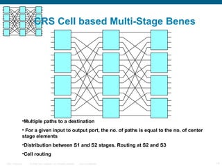
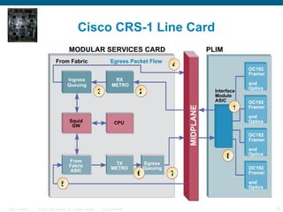
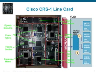
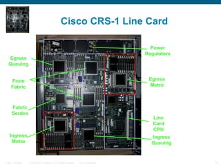
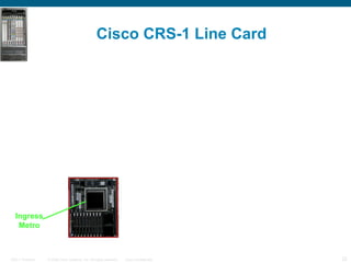
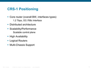
CRS-1 overview   TAU – Mar 07 Rami Zemach
Agenda Cisco’s high end router CRS-1 Future directions CRS-1’s NP  Metro (SPP) CRS-1’s Fabric CRS-1’s Line Card
What drove the CRS? OC768 Multi chassis Improved BW/Watt & BW/Space New OS (IOS-XR) Scalable control plane A sample taxonomy
Multiple router flavours Core OC-12 (622Mbps) and up (to OC-768 ~= 40Gbps) Big, fat, fast, expensive E.g. Cisco HFR, Juniper T-640 HFR: 1.2Tbps each, interconnect up to 72 giving 92Tbps, start at $450k Transit/Peering-facing OC-3 and up, good GigE density ACLs, full-on BGP, uRPF, accounting Customer-facing FR/ATM/… Feature set as above, plus fancy queues, etc Broadband aggregator High scalability: sessions, ports, reconnections Feature set as above Customer-premises (CPE) 100Mbps NAT, DHCP, firewall, wireless, VoIP, … Low cost, low-end, perhaps just software on a PC A sample taxonomy
Routers are pushed to the edge Over time routers are pushed to the edge as: BW requirements grow # of interfaces scale Different routers have different offering Interfaces types (core is mostly Eathernet) Features. Sometimes the same feature is implemented differently User interface Redundancy models Operating system Costumers look for: investment protection Stable network topology Feature parity Transparent scale A sample taxonomy
What does Scaling means … Interfaces (BW, number, variance) BW Packet rate Features (e.g. Support link BW in a flexible manner) More Routes Wider ECO system Effective Management (e.g. capability to support more BGP peers and more events) Fast Control (e.g. distribute routing information) Availability Serviceability Scaling is both up and down (logical routers) A sample taxonomy
Low BW feature rich – centralized  Shared Bus Line Interface Off-chip Buffer Route Table CPU Buffer Memory Line Interface MAC Line Interface MAC Line Interface MAC Typically <0.5Gb/s aggregate capacity CPU Memory
High BW – distributed Line Card MAC Local Buffer Memory CPU Card Line Card MAC Local Buffer Memory “ Crossbar”: Switched Backplane Line Interface CPU Memory Routing Table Fwding Table Typically <50Gb/s aggregate capacity Fwding Table
Distributed architecture challenges (examples) HW wise Switching fabric High BW switching QOS Traffic loss Speedup Data plane (SW) High BW / packet rate Limited resources (cpu, memory) Control plane (SW) High event rate Routing information distribution (e.g. forwarding tables)
CRS-1 System View  Fabric Shelves Contains Fabric cards, System Controllers Line Card Shelves Contains Route Processors, Line cards, System controllers NMS (Full system view) Out of band GE control bus to all shelf controllers 100m Shelf controller Shelf controller Sys controller Shelf controller Shelf controller Shelf controller Sys controller
CRS-1 System Architecture Fabric  Chassis FORWARDING PLANE   Up to 1152x40G 40G throughput per LC  MULTISTAGE SWITCH FABRIC  1296x1296 non-blocking buffered fabric Roots of Fabric architecture from Jon Turner’s early work DISTRIBUTED CONTROL PLANE Control SW distributed across  multiple control processors Interface Module MID-PLANE Line Card Line Card 8 of 8 2 of 8 1 of 8 S1 S1 S2 S2 S3 S3 S1 S2 S3 Cisco  SPP Cisco  SPP Modular Service Card 8K Qs 8K Qs µ µ Route Processor Route Processor
Switch Fabric challenges Scale - many ports Fast Distributed arbitration Minimum disruption with QOS model Minimum blocking Balancing Redundancy
Previous solution: GSR – Cell based XBAR w centralized scheduling Each LC has variable width links to and from the XBAR, depending on its bandwidth requirement Central scheduling ISLIP based Two request-grant-accept rounds Each arbitration round lasts one cell time Per destination LC virtual output queues Supports H/L priority Unicast/multicast
CRS Cell based Multi-Stage Benes Multiple paths to a destination For a given input to output port, the no. of paths is equal to the no. of center stage elements Distribution between S1 and S2 stages. Routing at S2 and S3 Cell routing
Fabric speedup Q-fabric tries to approximate an output buffered switch to minimize sub-port blocking Buffering at output allows better scheduling In single stage fabrics a 2X speedup very closely approximates an output buffered fabric *  For multi-stage the speedup factor to approx output buffered behavior is not known CRS-1  fabric’s  ~5X speed up constrained by available technology * Balaji prabhakar and nick McKeown  computer systems technical report CSL-TR-97-738. November 1997 .
Fabric Flow Control Overview Discard - time constant in the 10’s of mS range Originates from ‘from fab’ and is directed at ‘to fab’. Is a very fine level of granularity, discard to the level of individual destination raw queues. Back Pressure - time constant in the 10’s of   S range. Originates from the Fabric and is directed at ‘to fab’. Operates per priority at increasingly coarse  granularity: Fabric Destination (one of 4608) Fabric Group (one of 48 in phase one and 96 in phase two) Fabric (stop all traffic into the fabric per priority)
Reassembly Window Cells transitioning the Fabric take different paths between Sprayer and Sponge. Cells for the same packet will arrive out of order. The Reassembly Window for a given Source is defined as the the worst-case differential delay two cells from a packet encounter as they traverse the Fabric.  The Fabric limits the Reassembly Window
Linecard challenges Power COGS Multiple interfaces Intermediate buffering Speed up CPU subsystem
Cisco CRS-1 Line Card MODULAR SERVICES CARD PLIM MIDPLANE CPU Squid GW OC192 Framer  and Optics OC192 Framer  and Optics OC192 Framer  and Optics OC192 Framer  and Optics Egress Packet Flow From Fabric Interface  Module  ASIC RX  METRO Ingress Queuing TX METRO From Fabric ASIC Egress Queuing 4 1 8 7 6 5 2 3
Cisco CRS-1 Line Card MODULAR SERVICES CARD PLIM MIDPLANE CPU Squid GW OC192 Framer  and Optics OC192 Framer  and Optics OC192 Framer  and Optics OC192 Framer  and Optics Egress Packet Flow From Fabric Interface  Module  ASIC RX  METRO Ingress Queuing TX METRO From Fabric ASIC Egress Queuing 4 1 8 7 6 5 2 3 Line Card CPU Egress Metro Ingress Metro Ingress Queuing Power Regulators Fabric Serdes From Fabric Egress Queuing
Cisco CRS-1 Line Card Egress Metro Ingress Metro Line Card CPU Ingress Queuing Power Regulators Fabric Serdes From Fabric Egress Queuing
Cisco CRS-1 Line Card Ingress Metro
Metro Subsystem
Metro Subsystem What is it ? Massively Parallel NP Codename Metro Marketing name SPP  (Silicon Packet Processor) What were the Goals ? Programmability  Scalability Who designed & programmed it ? Cisco internal (Israel/San Jose) IBM and Tensilica partners
Metro Subsystem Metro 2500 Balls  250Mhz 35W TCAM 125MSPS 128kx144-bit entries 2 channels FCRAM 166Mhz DDR 9 Channels Lookups and Table Memory QDR2 SRAM 250Mhz DDR 5 Channels Policing state Classification results Queue length state
Metro Top Level Packet Out 96 Gb/s BW Packet In 96 Gb/s BW 18mmx18mm - IBM .13um 18M gates 8Mbit SRAM and RAs Control Processor Interface Proprietary 2Gb/s
Gee-whiz numbers 188 32-bit embedded Risc cores  ~50 Bips 175 Gb/s Memory BW 78 MPPS peak performance
Why Programmability ? Simple forwarding – not so simple Example FEATURES: MPLS–3 Labels Link Bundling (v4) Load Balancing L3 (v4) 1 Policier Check Marking TE/FRR Sampled Netflow WRED ACL IPv4 Multicast IPv6 Unicast Per prefix accounting GRE/L2TPv3 Tunneling RPF check (loose/strict) v4 Load Balancing V3 (v6) Link Bundling (v6) Congestion Control IPv4 Unicast lookup algorithm L2  Adjacency Programmability also means Ability to juggle feature ordering Support for heterogeneous mixes of feature chains Rapid introduction of new features (Feature Velocity) Hundreds of Load balancing Entries per Millions of Routes 100k+ of adjacencies Pointer to Statistics Counters L3 load balance entry L2 info Increasing pressure to add 1-2 level of increased indirection for High Availability and increased update rates  Lookup L3 info  Load Balancing and Adjacencies : Sram/DRAM Sram/Dram leaf policy based routing TCAM table TCAM PBR associative  Sram/DRAM 1:1 data
Metro Architecture Basics 96G 96G 96G 96 G PPE Resource Resource Packet tails stored on-chip Packet Distribution Run-to-completion (RTC) simple SW model  efficient heterogeneous feature  processing RTC and Non-Flow based Packet distribution means scalable architecture Costs High instruction BW supply Need RMW and flow ordering solutions  ~100Bytes of packet context sent to PPEs 188 PPE On-Chip Packet Buffer Resource Fabric
Metro Architecture Basics 96G 96G 96G 96 G PPE Resource Resource Packet Gather Gather of Packets involves : Assembly of final packets (at 100Gb/s)  Packet ordering after variable length processing Gathering without new packet distribution 188 PPE On-Chip Packet Buffer Resource Fabric
Metro Architecture Basics 96G 96G 96G 96 G PPE On-Chip Packet Buffer Resource Resource Packet Buffer accessible as Resource Resource Fabric is parallel wide multi-drop busses Resources consist of Memories Read-modify-write operations Performance heavy  mechanisms 188 PPE Resource Fabric
Metro Resources Statistics 512k TCAM Interface Tables Policing 100k+ Lookup Engine 2M Prefixes Table DRAM (10’sMB) Queue Depth State CCR April 2004 (vol. 34 no. 2) pp 97-123. “Tree Bitmap : Hardware/Software IP Lookups with Incremental Updates”, Will Eatherton et. Al. Lookup Engine uses TreeBitmap Algorithm FCRAM and on-chip memory High Update rates Configurable performance Vs density
Packet Processing Element (PPE) 16 PPE Clusters Each Cluster of 12 PPE’s .5sqmm per PPE
Packet Processing Element (PPE) Tensilica Xtensa core with Cisco enhancements 32-bit, 5-stage pipeline Code Density : 16/24 bit instructions Small instruction cache and data memory Cisco DMA engine – allows 3 outstanding Descriptor DMAs 10’s Kbytes Fast instruction memory 32-bit RISC ICACHE DATA Mem Cisco DMA instruction bus Memory mapped Regs Distribution Hdr Pkt Hdr Scratch Pad Processor   Core Cluster Instruction Memory Global Instruction  Memory Cluster Data Mux Unit To12  PPE’s Pkt Distribution From Resources Pkt Gather To Resources To12  PPE’s PPE
Programming Model and Efficiency Metro Programming Model Run to completion programming model Queued descriptor interface to resources Industry leveraged tool flow Efficiency Data Points 1 ucoder for 6 months: IPv4 with common features (ACL, PBR, QoS, etc..) CRS-1 initial shipping datapath code was done by ~3 people
Challenges Constant power battle Memory and IO Die Size Allocation PPEs Vs HW acceleration Scalability On-chip BW vs off-chip capacity Procket NPU 100MPPS - limited scaling Performance
future directions POP convergence Edge and core differences blur Smartness in the network More integrated services into the routing platforms Feature sets needing acceleration expanding Must leverage feature code across platforms/markets Scalability (# of processors, amount of memory, BW)
Summary Router business is diverse Network growth push routers to the  edge Costumers expect scale from one hand … and smart network Routers become a massive parallel processing machines
Questions ?   Thank You
 
CRS-1 Positioning Core router (overall BW, interfaces types)  1.2 Tbps, OC-768c Interface Distributed architecture Scalability/Performance Scalable control plane High Availability Logical Routers Multi-Chassis Support
Networks planes Networks are considered to have three planes / operating timescales Data : packet forwarding [μs, ns] Control : flows/connections [ ms, secs] Management : aggregates, networks  [ secs, hours ] Planes coupling is in descendent order (control-data more, management-control less)
Exact Matches in Ethernet Switches  Trees and Tries Binary Search Tree < > < > < > Binary Search Trie 0 1 0 1 0 1 111 010 Lookup time bounded and independent of table size, storage is O(NW) Lookup time dependent on table size, but independent of address length, storage is O(N) log 2 N N  entries
Exact Matches in Ethernet Switches  Multiway tries 16-ary Search Trie 0000, ptr 1111, ptr 0000, 0 1111, ptr 000011110000 0000, 0 1111, ptr 111111111111 Ptr=0 means no children Q: Why can’t we just make it a 2 48 -ary trie?

Cisco crs1

  • 1.
    CRS-1 overview TAU – Mar 07 Rami Zemach
  • 2.
    Agenda Cisco’s highend router CRS-1 Future directions CRS-1’s NP Metro (SPP) CRS-1’s Fabric CRS-1’s Line Card
  • 3.
    What drove theCRS? OC768 Multi chassis Improved BW/Watt & BW/Space New OS (IOS-XR) Scalable control plane A sample taxonomy
  • 4.
    Multiple router flavoursCore OC-12 (622Mbps) and up (to OC-768 ~= 40Gbps) Big, fat, fast, expensive E.g. Cisco HFR, Juniper T-640 HFR: 1.2Tbps each, interconnect up to 72 giving 92Tbps, start at $450k Transit/Peering-facing OC-3 and up, good GigE density ACLs, full-on BGP, uRPF, accounting Customer-facing FR/ATM/… Feature set as above, plus fancy queues, etc Broadband aggregator High scalability: sessions, ports, reconnections Feature set as above Customer-premises (CPE) 100Mbps NAT, DHCP, firewall, wireless, VoIP, … Low cost, low-end, perhaps just software on a PC A sample taxonomy
  • 5.
    Routers are pushedto the edge Over time routers are pushed to the edge as: BW requirements grow # of interfaces scale Different routers have different offering Interfaces types (core is mostly Eathernet) Features. Sometimes the same feature is implemented differently User interface Redundancy models Operating system Costumers look for: investment protection Stable network topology Feature parity Transparent scale A sample taxonomy
  • 6.
    What does Scalingmeans … Interfaces (BW, number, variance) BW Packet rate Features (e.g. Support link BW in a flexible manner) More Routes Wider ECO system Effective Management (e.g. capability to support more BGP peers and more events) Fast Control (e.g. distribute routing information) Availability Serviceability Scaling is both up and down (logical routers) A sample taxonomy
  • 7.
    Low BW featurerich – centralized Shared Bus Line Interface Off-chip Buffer Route Table CPU Buffer Memory Line Interface MAC Line Interface MAC Line Interface MAC Typically <0.5Gb/s aggregate capacity CPU Memory
  • 8.
    High BW –distributed Line Card MAC Local Buffer Memory CPU Card Line Card MAC Local Buffer Memory “ Crossbar”: Switched Backplane Line Interface CPU Memory Routing Table Fwding Table Typically <50Gb/s aggregate capacity Fwding Table
  • 9.
    Distributed architecture challenges(examples) HW wise Switching fabric High BW switching QOS Traffic loss Speedup Data plane (SW) High BW / packet rate Limited resources (cpu, memory) Control plane (SW) High event rate Routing information distribution (e.g. forwarding tables)
  • 10.
    CRS-1 System View Fabric Shelves Contains Fabric cards, System Controllers Line Card Shelves Contains Route Processors, Line cards, System controllers NMS (Full system view) Out of band GE control bus to all shelf controllers 100m Shelf controller Shelf controller Sys controller Shelf controller Shelf controller Shelf controller Sys controller
  • 11.
    CRS-1 System ArchitectureFabric Chassis FORWARDING PLANE Up to 1152x40G 40G throughput per LC MULTISTAGE SWITCH FABRIC 1296x1296 non-blocking buffered fabric Roots of Fabric architecture from Jon Turner’s early work DISTRIBUTED CONTROL PLANE Control SW distributed across multiple control processors Interface Module MID-PLANE Line Card Line Card 8 of 8 2 of 8 1 of 8 S1 S1 S2 S2 S3 S3 S1 S2 S3 Cisco SPP Cisco SPP Modular Service Card 8K Qs 8K Qs µ µ Route Processor Route Processor
  • 12.
    Switch Fabric challengesScale - many ports Fast Distributed arbitration Minimum disruption with QOS model Minimum blocking Balancing Redundancy
  • 13.
    Previous solution: GSR– Cell based XBAR w centralized scheduling Each LC has variable width links to and from the XBAR, depending on its bandwidth requirement Central scheduling ISLIP based Two request-grant-accept rounds Each arbitration round lasts one cell time Per destination LC virtual output queues Supports H/L priority Unicast/multicast
  • 14.
    CRS Cell basedMulti-Stage Benes Multiple paths to a destination For a given input to output port, the no. of paths is equal to the no. of center stage elements Distribution between S1 and S2 stages. Routing at S2 and S3 Cell routing
  • 15.
    Fabric speedup Q-fabrictries to approximate an output buffered switch to minimize sub-port blocking Buffering at output allows better scheduling In single stage fabrics a 2X speedup very closely approximates an output buffered fabric * For multi-stage the speedup factor to approx output buffered behavior is not known CRS-1 fabric’s ~5X speed up constrained by available technology * Balaji prabhakar and nick McKeown computer systems technical report CSL-TR-97-738. November 1997 .
  • 16.
    Fabric Flow ControlOverview Discard - time constant in the 10’s of mS range Originates from ‘from fab’ and is directed at ‘to fab’. Is a very fine level of granularity, discard to the level of individual destination raw queues. Back Pressure - time constant in the 10’s of  S range. Originates from the Fabric and is directed at ‘to fab’. Operates per priority at increasingly coarse granularity: Fabric Destination (one of 4608) Fabric Group (one of 48 in phase one and 96 in phase two) Fabric (stop all traffic into the fabric per priority)
  • 17.
    Reassembly Window Cellstransitioning the Fabric take different paths between Sprayer and Sponge. Cells for the same packet will arrive out of order. The Reassembly Window for a given Source is defined as the the worst-case differential delay two cells from a packet encounter as they traverse the Fabric. The Fabric limits the Reassembly Window
  • 18.
    Linecard challenges PowerCOGS Multiple interfaces Intermediate buffering Speed up CPU subsystem
  • 19.
    Cisco CRS-1 LineCard MODULAR SERVICES CARD PLIM MIDPLANE CPU Squid GW OC192 Framer and Optics OC192 Framer and Optics OC192 Framer and Optics OC192 Framer and Optics Egress Packet Flow From Fabric Interface Module ASIC RX METRO Ingress Queuing TX METRO From Fabric ASIC Egress Queuing 4 1 8 7 6 5 2 3
  • 20.
    Cisco CRS-1 LineCard MODULAR SERVICES CARD PLIM MIDPLANE CPU Squid GW OC192 Framer and Optics OC192 Framer and Optics OC192 Framer and Optics OC192 Framer and Optics Egress Packet Flow From Fabric Interface Module ASIC RX METRO Ingress Queuing TX METRO From Fabric ASIC Egress Queuing 4 1 8 7 6 5 2 3 Line Card CPU Egress Metro Ingress Metro Ingress Queuing Power Regulators Fabric Serdes From Fabric Egress Queuing
  • 21.
    Cisco CRS-1 LineCard Egress Metro Ingress Metro Line Card CPU Ingress Queuing Power Regulators Fabric Serdes From Fabric Egress Queuing
  • 22.
    Cisco CRS-1 LineCard Ingress Metro
  • 23.
  • 24.
    Metro Subsystem Whatis it ? Massively Parallel NP Codename Metro Marketing name SPP (Silicon Packet Processor) What were the Goals ? Programmability Scalability Who designed & programmed it ? Cisco internal (Israel/San Jose) IBM and Tensilica partners
  • 25.
    Metro Subsystem Metro2500 Balls 250Mhz 35W TCAM 125MSPS 128kx144-bit entries 2 channels FCRAM 166Mhz DDR 9 Channels Lookups and Table Memory QDR2 SRAM 250Mhz DDR 5 Channels Policing state Classification results Queue length state
  • 26.
    Metro Top LevelPacket Out 96 Gb/s BW Packet In 96 Gb/s BW 18mmx18mm - IBM .13um 18M gates 8Mbit SRAM and RAs Control Processor Interface Proprietary 2Gb/s
  • 27.
    Gee-whiz numbers 18832-bit embedded Risc cores ~50 Bips 175 Gb/s Memory BW 78 MPPS peak performance
  • 28.
    Why Programmability ?Simple forwarding – not so simple Example FEATURES: MPLS–3 Labels Link Bundling (v4) Load Balancing L3 (v4) 1 Policier Check Marking TE/FRR Sampled Netflow WRED ACL IPv4 Multicast IPv6 Unicast Per prefix accounting GRE/L2TPv3 Tunneling RPF check (loose/strict) v4 Load Balancing V3 (v6) Link Bundling (v6) Congestion Control IPv4 Unicast lookup algorithm L2 Adjacency Programmability also means Ability to juggle feature ordering Support for heterogeneous mixes of feature chains Rapid introduction of new features (Feature Velocity) Hundreds of Load balancing Entries per Millions of Routes 100k+ of adjacencies Pointer to Statistics Counters L3 load balance entry L2 info Increasing pressure to add 1-2 level of increased indirection for High Availability and increased update rates Lookup L3 info Load Balancing and Adjacencies : Sram/DRAM Sram/Dram leaf policy based routing TCAM table TCAM PBR associative Sram/DRAM 1:1 data
  • 29.
    Metro Architecture Basics96G 96G 96G 96 G PPE Resource Resource Packet tails stored on-chip Packet Distribution Run-to-completion (RTC) simple SW model efficient heterogeneous feature processing RTC and Non-Flow based Packet distribution means scalable architecture Costs High instruction BW supply Need RMW and flow ordering solutions ~100Bytes of packet context sent to PPEs 188 PPE On-Chip Packet Buffer Resource Fabric
  • 30.
    Metro Architecture Basics96G 96G 96G 96 G PPE Resource Resource Packet Gather Gather of Packets involves : Assembly of final packets (at 100Gb/s) Packet ordering after variable length processing Gathering without new packet distribution 188 PPE On-Chip Packet Buffer Resource Fabric
  • 31.
    Metro Architecture Basics96G 96G 96G 96 G PPE On-Chip Packet Buffer Resource Resource Packet Buffer accessible as Resource Resource Fabric is parallel wide multi-drop busses Resources consist of Memories Read-modify-write operations Performance heavy mechanisms 188 PPE Resource Fabric
  • 32.
    Metro Resources Statistics512k TCAM Interface Tables Policing 100k+ Lookup Engine 2M Prefixes Table DRAM (10’sMB) Queue Depth State CCR April 2004 (vol. 34 no. 2) pp 97-123. “Tree Bitmap : Hardware/Software IP Lookups with Incremental Updates”, Will Eatherton et. Al. Lookup Engine uses TreeBitmap Algorithm FCRAM and on-chip memory High Update rates Configurable performance Vs density
  • 33.
    Packet Processing Element(PPE) 16 PPE Clusters Each Cluster of 12 PPE’s .5sqmm per PPE
  • 34.
    Packet Processing Element(PPE) Tensilica Xtensa core with Cisco enhancements 32-bit, 5-stage pipeline Code Density : 16/24 bit instructions Small instruction cache and data memory Cisco DMA engine – allows 3 outstanding Descriptor DMAs 10’s Kbytes Fast instruction memory 32-bit RISC ICACHE DATA Mem Cisco DMA instruction bus Memory mapped Regs Distribution Hdr Pkt Hdr Scratch Pad Processor Core Cluster Instruction Memory Global Instruction Memory Cluster Data Mux Unit To12 PPE’s Pkt Distribution From Resources Pkt Gather To Resources To12 PPE’s PPE
  • 35.
    Programming Model andEfficiency Metro Programming Model Run to completion programming model Queued descriptor interface to resources Industry leveraged tool flow Efficiency Data Points 1 ucoder for 6 months: IPv4 with common features (ACL, PBR, QoS, etc..) CRS-1 initial shipping datapath code was done by ~3 people
  • 36.
    Challenges Constant powerbattle Memory and IO Die Size Allocation PPEs Vs HW acceleration Scalability On-chip BW vs off-chip capacity Procket NPU 100MPPS - limited scaling Performance
  • 37.
    future directions POPconvergence Edge and core differences blur Smartness in the network More integrated services into the routing platforms Feature sets needing acceleration expanding Must leverage feature code across platforms/markets Scalability (# of processors, amount of memory, BW)
  • 38.
    Summary Router businessis diverse Network growth push routers to the edge Costumers expect scale from one hand … and smart network Routers become a massive parallel processing machines
  • 39.
    Questions ? Thank You
  • 40.
  • 41.
    CRS-1 Positioning Corerouter (overall BW, interfaces types) 1.2 Tbps, OC-768c Interface Distributed architecture Scalability/Performance Scalable control plane High Availability Logical Routers Multi-Chassis Support
  • 42.
    Networks planes Networksare considered to have three planes / operating timescales Data : packet forwarding [μs, ns] Control : flows/connections [ ms, secs] Management : aggregates, networks [ secs, hours ] Planes coupling is in descendent order (control-data more, management-control less)
  • 43.
    Exact Matches inEthernet Switches Trees and Tries Binary Search Tree < > < > < > Binary Search Trie 0 1 0 1 0 1 111 010 Lookup time bounded and independent of table size, storage is O(NW) Lookup time dependent on table size, but independent of address length, storage is O(N) log 2 N N entries
  • 44.
    Exact Matches inEthernet Switches Multiway tries 16-ary Search Trie 0000, ptr 1111, ptr 0000, 0 1111, ptr 000011110000 0000, 0 1111, ptr 111111111111 Ptr=0 means no children Q: Why can’t we just make it a 2 48 -ary trie?

Editor's Notes

  • #12 8
  • #16 Single stage w/ VOQ approx an output buffered fabric Output buffered switch only buffers at output so has minimal blocking impact OB switch can better schedule service if Qs are at output