Downloaded 366 times

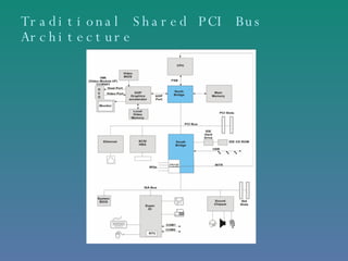
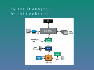
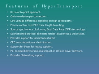
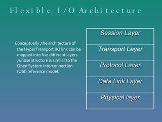
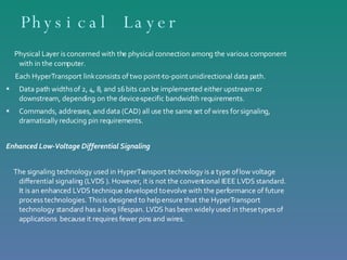


HyperTransport is a high-speed serial point-to-point interconnect that was developed as an alternative to traditional I/O buses to address increasing bandwidth needs. It provides high bandwidth, low latency communication between components using a packet-based protocol and source synchronous signaling. HyperTransport supports multiple topologies including daisy chaining, switches, and stars and can scale from personal computers to large multiprocessor systems. It has largely replaced front-side buses and can integrate processors, memory, and I/O subsystems more efficiently than previous bus architectures.


