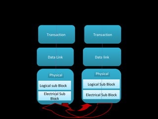
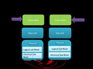
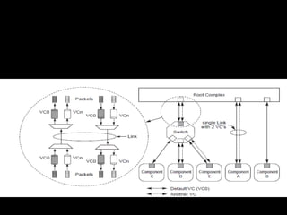
The document discusses the key aspects of the PCIe transaction layer including:
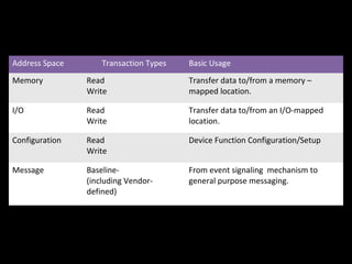
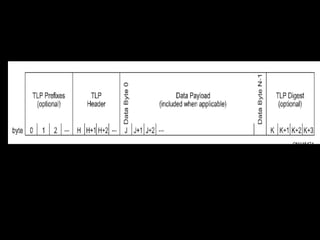
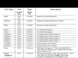
- It defines the packet format and different transaction types for memory, I/O, configuration and messages.
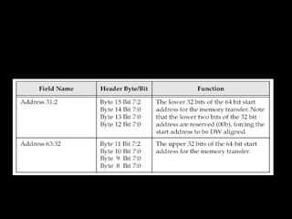
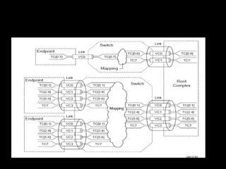
- Rules are specified for TLPs with data payloads, digest rules, address-based and ID-based routing.
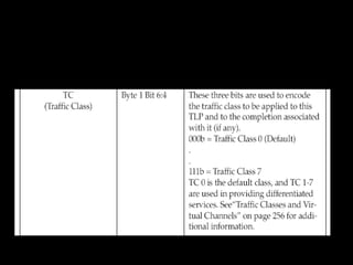
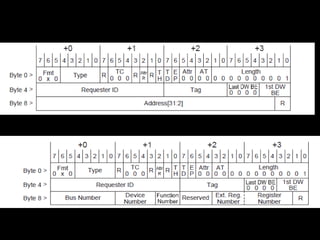
- Transaction descriptors contain the transaction ID, attributes and traffic class fields.
- Memory, I/O and configuration request rules and completion rules are also outlined.


![Common Packet Header Fields
Fields Present in All TLP Headers
Fmt[2:0] Corresponding TLP Format
000b 3 DW header, no data
001b 4 DW header, no data
010b 3 DW header, with data
011b 4DW header, with data
100b TLP Prefix
Fmt[2:0] Field Values
24/04/17 11](https://image.slidesharecdn.com/pcietllayer3-170424202114/85/Pc-ie-tl_layer-3-11-320.jpg)

![Length[9:0] Field Encoding
24/04/17 14
Length[9:0] Field Encoding](https://image.slidesharecdn.com/pcietllayer3-170424202114/85/Pc-ie-tl_layer-3-14-320.jpg)
![TLPs with Data Payloads - Rules
ü
Length is specified as an integral number of DW.
ü
Length[9:0] is Reserved for all Messages except those which
explicitly refer to a Data Length.
ü
The Transmitter of a TLP with a data payload must not allow the
data payload length as given by the TLP’s Length field to exceed
the length specified by the value in the Max_Payload_Size field of
the Transmitter’s Device Control register taken as an integral
number of DW.
ü
The size of the data payload of a Received TLP as given by the
TLP’s Length field must not exceed the length specified by the
value in the Max_Payload_Size field of the Receiver’s Device
Control register taken as an integral number of DW.
24/04/17 15](https://image.slidesharecdn.com/pcietllayer3-170424202114/85/Pc-ie-tl_layer-3-15-320.jpg)


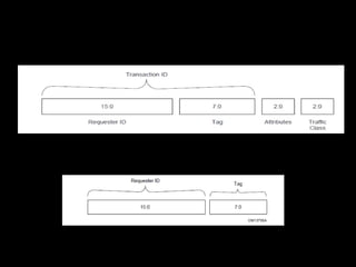
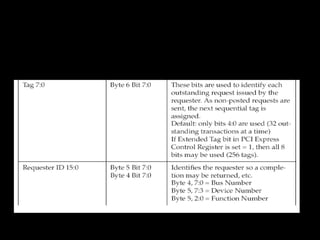
![Transaction ID Field
ü
The Transaction ID field consists of two major sub-fields:
§
Requester ID
§
Tag
ü
Tag[7:0] is an 8-bit field generated by each Requester, and it
must be unique for all outstanding Requests that require a
Completion for that Requester.
ü
Transaction ID is included with all Requests and Completions.
ü
The Requester ID is a 16-bit value that is unique for every PCI
Express Function within a Hierarchy.
ü
A Switch must forward Requests without modifying the
Transaction ID.
24/04/17 27](https://image.slidesharecdn.com/pcietllayer3-170424202114/85/Pc-ie-tl_layer-3-27-320.jpg)

![Relaxed Ordering & ID Based
Ordering Attributes
ü
Attr[1] is not applicable and must be set to 0b for configuration
requests, I/O requests , Memory requests that are Message
signalled Interrupts, and Message Requests.
ü
Attribute bit [2], IDO, is reserved for Configuration Requests and
I/O Requests. IDO is not reserved for all Memory Requests and
message requests.
24/04/17 29](https://image.slidesharecdn.com/pcietllayer3-170424202114/85/Pc-ie-tl_layer-3-29-320.jpg)


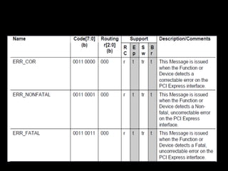
![24/04/17 38
Message Routing
ü
Message routing is determined using the r[2:0] sub-field of the
type field.
Message Routing](https://image.slidesharecdn.com/pcietllayer3-170424202114/85/Pc-ie-tl_layer-3-38-320.jpg)

![ü
Completions route by ID, and use a 3 DW header.
ü
Completions contain the following additional fields
§
Completer ID[15:0] – Identifies the Completer
§
Completion Status[2:0] – Indicates the status for a Completion
§
BCM – Byte Count Modified – this bit must not set by PCI
Express Completers, and may only be set by PCI-X completers
§
Byte Count[11:0] – The remaining byte count for Request
§
Tag[7:0] – in combination with the Requester ID field,
corresponds to the Transaction ID
§
Lower Address[6:0] – lower byte address for starting byte of
Completion
24/04/17 41
Completion
Rules](https://image.slidesharecdn.com/pcietllayer3-170424202114/85/Pc-ie-tl_layer-3-41-320.jpg)
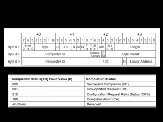
![24/04/17 43
Completion
ID[15:0]
Non-ARI Completion Header format
ARI Completion ID](https://image.slidesharecdn.com/pcietllayer3-170424202114/85/Pc-ie-tl_layer-3-43-320.jpg)


![Osi week10(1) [autosaved] by Gulshan K Maheshwari(QAU)](https://cdn.slidesharecdn.com/ss_thumbnails/osi-week101autosaved-190228163325-thumbnail.jpg?width=640&height=640&fit=bounds)


