Downloaded 511 times


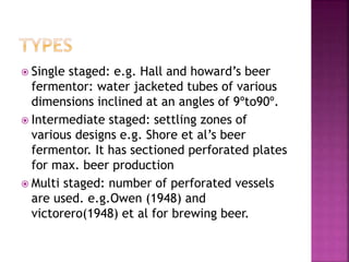
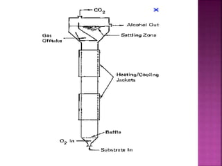
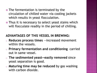
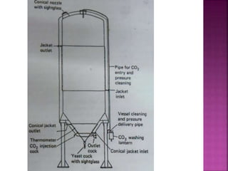
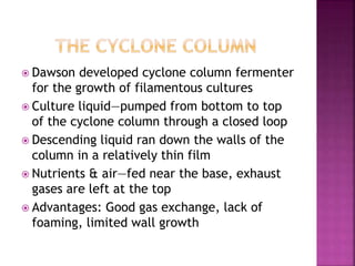
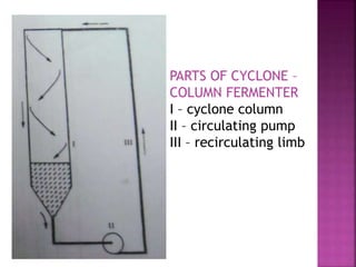


This document discusses various types of fermenters used in industrial fermentation processes. It describes 7 types of fermenters: 1) Waldhof fermenter, 2) Acetators and cavitators, 3) Tower fermenter, 4) Cylindro-conical vessels, 5) Air lift fermenter, 6) Deep jet fermenter, 7) The cyclone column. For each type, it provides details on their design, operating principles, and applications. The key advantages of each fermenter type for different fermentation processes are highlighted.


![谷歌留痕技术 [ 𝙩𝙤𝙥 𝟮𝟯𝟯. 𝙘 𝙤𝙢 ]](https://cdn.slidesharecdn.com/ss_thumbnails/top233-260130174328-3833018c-thumbnail.jpg?width=640&height=640&fit=bounds)


