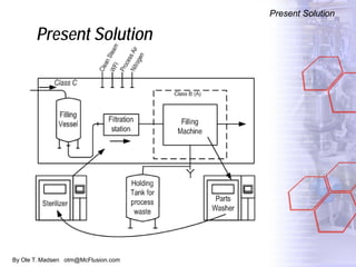
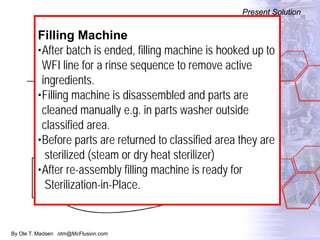
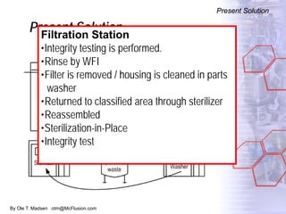
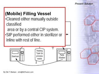
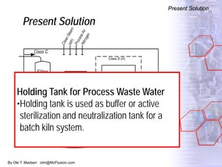
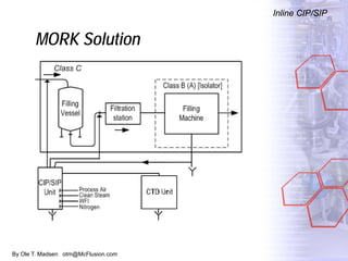
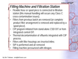
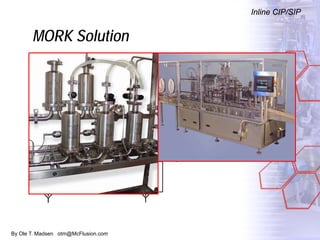
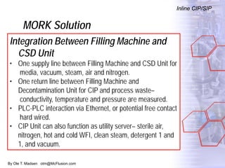
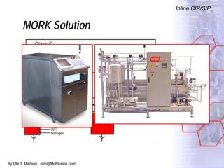
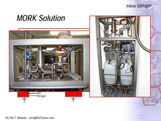
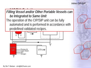
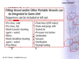
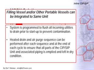
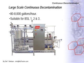
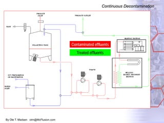
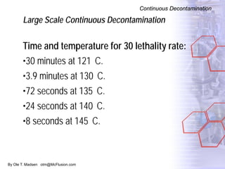
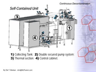
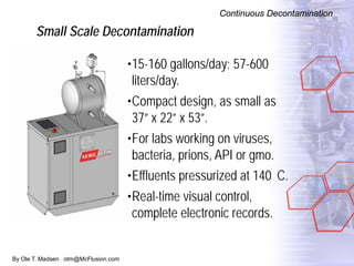
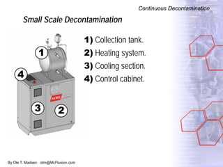
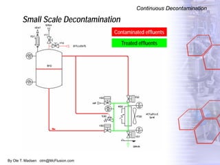
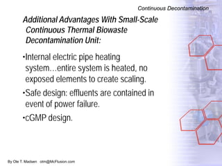
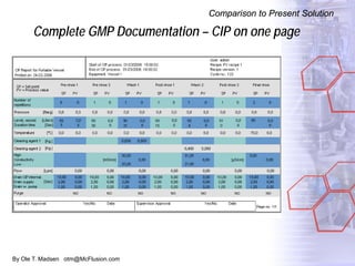
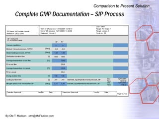
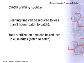
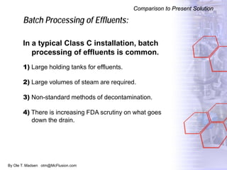
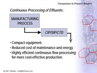
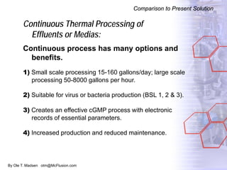
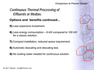
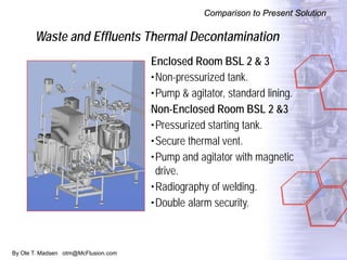
1. By Ole T. Madsen otm@McFlusion.com
New Solutions for Cleaning,
Sterilization and Decontamination
of Process Equipment
for Aseptic Sterile, Biotech and Vaccine
Manufacturing
Process Cleaning & Sanitizing, and Continuous
Thermal Decontamination of Effluents.
2. By Ole T. Madsen otm@McFlusion.com
Agenda
Present Solution
Inline CIP/SIP of Filling Machine
Continuous Decontamination of Effluents
Comparison to Present Solution
3. By Ole T. Madsen otm@McFlusion.com
Agenda
Present Solution
Inline CIP/SIP of Filling Machine
Continuous Decontamination of Effluents
Comparison to Present Solution
4. By Ole T. Madsen otm@McFlusion.com
Present Solution
Present Solution
5. By Ole T. Madsen otm@McFlusion.com
Present Solution
Present Solution
Filling Machine
•After batch is ended, filling machine is hooked up to
WFI line for a rinse sequence to remove active
ingredients.
•Filling machine is disassembled and parts are
cleaned manually e.g. in parts washer outside
classified area.
•Before parts are returned to classified area they are
sterilized (steam or dry heat sterilizer)
•After re-assembly filling machine is ready for
Sterilization-in-Place.
6. By Ole T. Madsen otm@McFlusion.com
Present Solution
Present Solution
Filtration Station
•Integrity testing is performed.
•Rinse by WFI
•Filter is removed / housing is cleaned in parts
washer
•Returned to classified area through sterilizer
•Reassembled
•Sterilization-in-Place
•Integrity test
7. By Ole T. Madsen otm@McFlusion.com
Present Solution
Present Solution
(Mobile) Filling Vessel
•Cleaned either manually outside
classified
area or by a central CIP system.
•SIP performed either in sterilizer or
inline with rest of line.
8. By Ole T. Madsen otm@McFlusion.com
Present Solution
Present Solution
Holding Tank for Process Waste Water
•Holding tank is used as buffer or active
sterilization and neutralization tank for a
batch kiln system.
9. By Ole T. Madsen otm@McFlusion.com
Agenda
Present Solution
Inline CIP/SIP of Filling Machine—MORK solution
Continuous Decontamination of Effluents
Comparison to Present Solution
Conclusion
10. By Ole T. Madsen otm@McFlusion.com
MORK Solution
Inline CIP/SIP
11. By Ole T. Madsen otm@McFlusion.com
MORK Solution
Inline CIP/SIP
Filling Machine and Filtration Station
• Flexible hose or spool piece is connected to filtration
station (this manual handling will secure any Class C
cross-contamination issues).
• Filters from previous batch are removed (or complete
product filter arrangement is removed and replaced by a
spool piece).
• CIP program initiated from stand-alone CSD OIT or from
integrated control OIT.
• Thermal decontamination of effluents integrated with CIP
process.
• Filters with filter housings are inserted inline.
• SIP is performed and air removed
• Filling machine pressurized with nitrogen.
12. By Ole T. Madsen otm@McFlusion.com
MORK Solution
Inline CIP/SIP
13. By Ole T. Madsen otm@McFlusion.com
MORK Solution
Inline CIP/SIP
Integration Between Filling Machine and
CSD Unit
• One supply line between Filling Machine and CSD Unit for
media, vacuum, steam, air and nitrogen.
• One return line between Filling Machine and
Decontamination Unit for CIP and process waste–
conductivity, temperature and pressure are measured.
• PLC-PLC interaction via Ethernet, or potential free contact
hard wired.
• CIP Unit can also function as utility server– sterile air,
nitrogen, hot and cold WFI, clean steam, detergent 1 and
1, and vacuum.
14. By Ole T. Madsen otm@McFlusion.com
MORK Solution
Inline CIP/SIP
15. By Ole T. Madsen otm@McFlusion.com
MORK Solution
Inline CIP/SIP
16. By Ole T. Madsen otm@McFlusion.com
MORK Solution
Inline CIP/SIP
Filling Vessel and/or Other Portable Vessels can
be Integrated to Same Unit
The operation of the CIP/SIP unit can be fully
automated and is performed in accordance with
predefined validated recipes.
17. By Ole T. Madsen otm@McFlusion.com
MORK Solution
Inline CIP/SIP
Filling Vessel and/or Other Portable Vessels can
be Integrated to Same Unit
Sequences can be included or left out:
•Pre-rinse, cold
•Pre-rinse, hot
•Wash (caustic cleaning
agent + water)
•Rinse
•Wash (Acidified cleaning
agent + water)
•Post Rinse
•Final rinse (USP water)
•Drain and purge with
heated air
•Pressure test before
sterilization
•Vacuum
•Sterilization
•Drying/Cooling
18. By Ole T. Madsen otm@McFlusion.com
MORK Solution
Inline CIP/SIP
Filling Vessel and/or Other Portable Vessels can
be Integrated to Same Unit
• System is programmed to flush all incoming utilities
to drain prior to start-up to prevent contamination.
• Heated drain and air purge sequence can be
performed after each sequence and at the end of
each cycle to ensure that all parts of the CIP/SIP
Unit and associated piping is emptied and left in dry
condition.
19. By Ole T. Madsen otm@McFlusion.com
MORK Solution
Inline CIP/SIP
Filling Vessel and/or Other Portable Vessels can
be Integrated to Same Unit
• All sequences can be performed in “once-through”
(single-pass) or “re-circulation” modes, except for
final rinse, which always will be performed as
“once-through.”
20. By Ole T. Madsen otm@McFlusion.com
MORK Solution
Inline CIP/SIP
Filling Vessel and/or Other Portable Vessels can
be Integrated to Same Unit
• The final rinse of the cleaning process is monitored
by conductivity.
• The sterilization process, which can be chosen as
part of the CIP cycle or started as an independent
cycle, begins with a vacuum cycle to remove any air
in the vessel. The vacuum cycle can be repeated as
many times as needed.
21. By Ole T. Madsen otm@McFlusion.com
MORK Solution
Inline CIP/SIP
Filling Vessel and/or Other Portable Vessels can
be Integrated to Same Unit
• The CIP/SIP unit uses the temperature sensor on the
return line to calculate the F0 value. This is reached
with a temperature of approximately 121 C in the time
required to obtain F0 > 15.
T0-Product temperature at the time t
A minimum log 12 reduction of spores is achieved.
0
T
T
T -121
10F = 10 dt
1
z
0
∫
22. By Ole T. Madsen otm@McFlusion.com
MORK Solution
Inline CIP/SIP
Filling Vessel and/or Other Portable Vessels can
be Integrated to Same Unit
• The SIP cycle will sterilize the filling system and the
portable vessels, e.g. 121 C until either a
programmable F0 value is achieved at the coldest
point or until a programmable time limit is achieved.
23. By Ole T. Madsen otm@McFlusion.com
Agenda
Present Solution
Inline CIP/SIP of Filling Machine
Continuous Decontamination of Effluents
Comparison to Present Solution
24. By Ole T. Madsen otm@McFlusion.com
Large Scale Continuous Decontamination
Continuous Decontamination
•80-8,000 gallons/hour.
•Suitable for BSL 1, 2 & 3.
25. By Ole T. Madsen otm@McFlusion.com
Large Scale Continuous Decontamination
Continuous Decontamination
•Effluents continuously collected in a collecting tank.
•Decontamination begins when level set point is
reached.
•When the treatment temperature is reached, effluents
are pumped and continuously treated before disposal.
•In the event of power failure or at the end of the cycle,
effluents flow back to the collecting tank.
•The system is then automatically cleaned, sanitized
and ready for a new decontamination cycle.
26. By Ole T. Madsen otm@McFlusion.com
Large Scale Continuous Decontamination
Continuous Decontamination
Contaminated effluents
Treated effluents
27. By Ole T. Madsen otm@McFlusion.com
Large Scale Continuous Decontamination
Continuous Decontamination
Time and temperature for 30 lethality rate:
•30 minutes at 121 C.
•3.9 minutes at 130 C.
•72 seconds at 135 C.
•24 seconds at 140 C.
•8 seconds at 145 C.
28. By Ole T. Madsen otm@McFlusion.com
Self-Contained Unit
Continuous Decontamination
1) Collecting Tank; 2) Double secured pump system;
3) Thermal section; 4) Control cabinet.
29. By Ole T. Madsen otm@McFlusion.com
Small Scale Decontamination
Continuous Decontamination
•15-160 gallons/day; 57-600
liters/day.
•Compact design, as small as
37” x 22” x 53”.
•For labs working on viruses,
bacteria, prions, API or gmo.
•Effluents pressurized at 140 C.
•Real-time visual control,
complete electronic records.
30. By Ole T. Madsen otm@McFlusion.com
Small Scale Decontamination
Continuous Decontamination
1) Collection tank.
2) Heating system.
3) Cooling section.
4) Control cabinet.
31. By Ole T. Madsen otm@McFlusion.com
Continuous Decontamination
Small Scale Decontamination
Contaminated effluents
Treated effluents
32. By Ole T. Madsen otm@McFlusion.com
Continuous Decontamination
Additional Advantages With Small-Scale
Continuous Thermal Biowaste
Decontamination Unit:
•Internal electric pipe heating
system…entire system is heated, no
exposed elements to create scaling.
•Safe design: effluents are contained in
event of power failure.
•cGMP design.
33. By Ole T. Madsen otm@McFlusion.com
Agenda
Present Solution
Inline CIP/SIP of Filling Machine
Continuous Decontamination of Effluents
Comparison to Present Solution
Conclusion
34. By Ole T. Madsen otm@McFlusion.com
Comparison to Present Solution
Complete GMP Documentation – CIP on one page
35. By Ole T. Madsen otm@McFlusion.com
Complete GMP Documentation – SIP Process
Comparison to Present Solution
36. By Ole T. Madsen otm@McFlusion.com
Comparison to Present Solution
CIP/SIP of Filling machine
Cleaning time can be reduced to less
than 2 hours (batch to batch).
Total sterilization time can be reduced
to 45 minutes (batch to batch).
37. By Ole T. Madsen otm@McFlusion.com
Batch Processing of Effluents:
In a typical Class C installation, batch
processing of effluents is common.
1) Large holding tanks for effluents.
2) Large volumes of steam are required.
3) Non-standard methods of decontamination.
4) There is increasing FDA scrutiny on what goes
down the drain.
Comparison to Present Solution
38. By Ole T. Madsen otm@McFlusion.com
Continuous Processing of Effluents:
Y• Compact equipment.
• Reduced cost of maintenance and energy.
• Highly efficient continuous flow processing
for more cost-effective production.
CIP/SIP/CTD
MANUFACTURING
PROCESS
Comparison to Present Solution
39. By Ole T. Madsen otm@McFlusion.com
Continuous Thermal Processing of
Effluents or Medias:
Continuous process has many options and
benefits.
1) Small scale processing 15-160 gallons/day; large scale
processing 50-8000 gallons per hour.
2) Suitable for virus or bacteria production (BSL 1, 2 & 3).
3) Creates an effective cGMP process with electronic
records of essential parameters.
4) Increased production and reduced maintenance.
Comparison to Present Solution
40. By Ole T. Madsen otm@McFlusion.com
Continuous Thermal Processing of
Effluents or Medias:
Options and benefits continued...
5) Less expensive investment.
6) Less energy comsumption – 8 kW compared to 100 kW
for a classic solution.
7) Compact installation, reduced space requirement.
8) Automatic descaling and descaling test.
9) No cooling water needed for continuous solution.
Comparison to Present Solution
41. By Ole T. Madsen otm@McFlusion.com
Waste and Effluents Thermal Decontamination
Comparison to Present Solution
Enclosed Room BSL 2 & 3
•Non-pressurized tank.
•Pump & agitator, standard lining.
Non-Enclosed Room BSL 2 &3
•Pressurized starting tank.
•Secure thermal vent.
•Pump and agitator with magnetic
drive.
•Radiography of welding.
•Double alarm security.