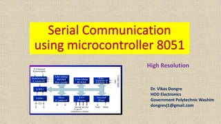
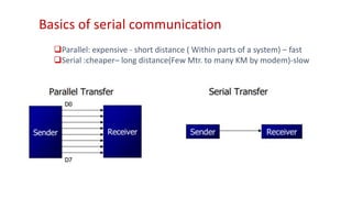
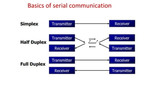
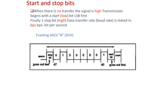
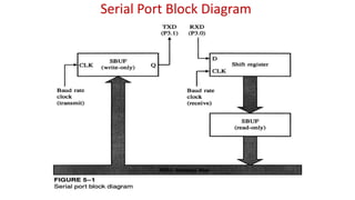
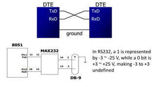
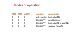
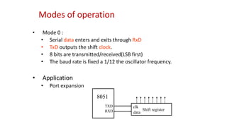
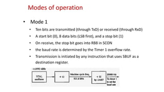
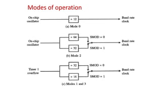
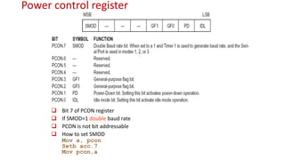
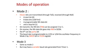
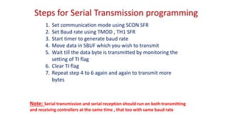
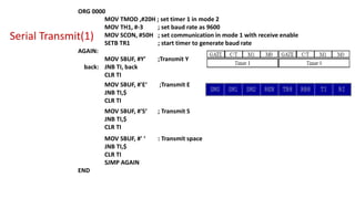
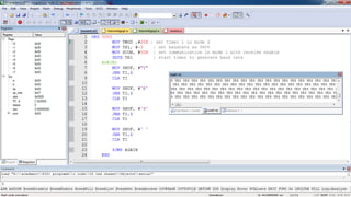
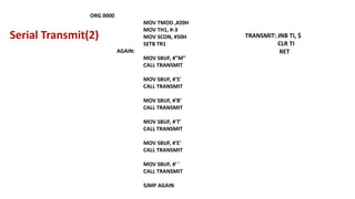
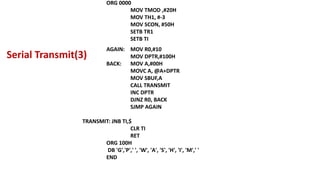
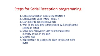
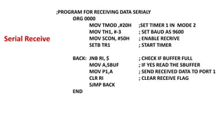
Dr. Vikas Dongre
HOD Electronics
Government Polytechnic Washim
dongrevj1@gmail.com
High Resolution
Objectives
• Types of communication
• Baud rate setting
• Various SFRs used for serial communication
• Various modes of serial communication
• Programs for transmission and reception with
demonstration
UART
UART Universal Asynchronous Receiver Transmitter
Basics of serial communication
Parallel: expensive - short distance ( Within parts of a system) – fast
Serial :cheaper– long distance(Few Mtr. to many KM by modem)-slow
Basics of serial communication
Start and stop bits
When there is no transfer the signal is high Transmission
begins with a start (low) bit LSB first
Finally 1 stop bit (high) Data transfer rate (baud rate) is stated in
bps bps: bit per second
Framing ASCII “A” (41H)
Serial Port Block Diagram
In RS232, a 1 is represented
by -3 ~ -25 V, while a 0 bit is
+3 ~ +25 V, making -3 to +3
undefined
Micro
contol
ler 1
Max 232
Micro
contol
ler 2
Max 232
Tx
TxRx
Rx
How to communicate 8051 to PC
 Connect TXD to RXD and RXD to TXD from pc to 8051
 Use max232 to transform signal from TTL level to RS232 level
 The baud rate of the transmitting 8051 must matched the baud
rate of the receiving 8051 or pc
 PC standard baud rate
 2400-4800-9600-14400-19200-28800-33600-57600
 Timer 1 in mode 2 ( auto reload) is used for baud rate generation
 The 8051 UART divides the machine cycle frequency by 32
 Machine cycle is 1/12 XTAL frequency
TH1=FF+1- required Count
RxD and TxD pins in the 8051
• TxD pin 11 of the 8051 (P3.1)
• RxD pin 10 of the 8051 (P3.0)
SBUF register
MOV SBUF, #’D’ ;load SBUF=44H, ASCII for ‘D’
MOV SBUF, A ;copy accumulator into SBUF
MOV A, SBUF ;copy SBUF into accumulator
SFRs used
SBUF, SCON, PCON for actual communication
TCON,TMOD,TH1, TL1 for Baud Rate generation
Serial control (SCON) Register
Modes of operation
SM0 SM1 MODE operation transmit rate
0 0 0 shift register fixed (xtal/12)
0 1 1 8 bit UART variable (timer1)
1 0 2 9 bit UART fixed (xtal/32 or xtal/64)
1 1 3 9 bit UART variable (timer1)
Modes of operation
• Mode 0 :
• Serial data enters and exits through RxD
• TxD outputs the shift clock.
• 8 bits are transmitted/received(LSB first)
• The baud rate is fixed a 1/12 the oscillator frequency.
• Application
• Port expansion
8051
TXD
RXD Shift register
clk
data
Modes of operation
• Mode 1
• Ten bits are transmitted (through TxD) or received (through RxD)
• A start bit (0), 8 data bits (LSB first), and a stop bit (1)
• On receive, the stop bit goes into RB8 in SCON
• the baud rate is determined by the Timer 1 overflow rate.
• Transmission is initiated by any instruction that uses SBUF as a
destination register.
Modes of operation
Power control register
 Bit 7 of PCON register
 If SMOD=1 double baud rate
 PCON is not bit addressable
 How to set SMOD
Mov a, pcon
Setb acc.7
Mov pcon,a
• Mode 2 :
• Eleven bits are transmitted (through TxD), received (through RxD)
• A start bit (0)
• 8 data bits (LSB first)
• A programmable 9th data bit
• and a stop bit (1)
• On transmit, the 9th bit (TB8) can be assigned 0 or 1.
• On receive, the 9th data bit goes into RB8 in SCON.
• the 9th can be parity bit
• The baud rate is programmable to 1/32 or 1/64 the oscillator frequency in
Mode 2 by SMOD bit in PCON register
• Mode 3
• Same as mode 2
• But may have a variable baud rate generated from Timer 1.
Modes of operation
Steps for Serial Transmission programming
1. Set communication mode using SCON SFR
2. Set Baud rate using TMOD , TH1 SFR
3. Start timer to generate baud rate
4. Move data in SBUF which you wish to transmit
5. Wait till the data byte is transmitted by monitoring the
setting of TI flag
6. Clear TI flag
7. Repeat step 4 to 6 again and again to transmit more
bytes
Note: Serial transmission and serial reception should run on both transmitting
and receiving controllers at the same time , that too with same baud rate
Serial Transmit(1)
ORG 0000
MOV TMOD ,#20H ; set timer 1 in mode 2
MOV TH1, #-3 ; set baud rate as 9600
MOV SCON, #50H ; set communication in mode 1 with receive enable
SETB TR1 ; start timer to generate baud rate
AGAIN:
MOV SBUF, #Y’ ;Transmit Y
back: JNB TI, back
CLR TI
MOV SBUF, #'E‘ ;Transmit E
JNB TI,$
CLR TI
MOV SBUF, #'S‘ ; Transmit S
JNB TI,$
CLR TI
MOV SBUF, #' ‘ : Transmit space
JNB TI,$
CLR TI
SJMP AGAIN
END
ORG 0000
MOV TMOD ,#20H
MOV TH1, #-3
MOV SCON, #50H
SETB TR1
AGAIN:
MOV SBUF, #"M"
CALL TRANSMIT
MOV SBUF, #'S'
CALL TRANSMIT
MOV SBUF, #'B'
CALL TRANSMIT
MOV SBUF, #'T'
CALL TRANSMIT
MOV SBUF, #'E'
CALL TRANSMIT
MOV SBUF, #' '
CALL TRANSMIT
SJMP AGAIN
TRANSMIT: JNB TI, $
CLR TI
RET
Serial Transmit(2)
ORG 0000
MOV TMOD ,#20H
MOV TH1, #-3
MOV SCON, #50H
SETB TR1
SETB TI
AGAIN: MOV R0,#10
MOV DPTR,#100H
BACK: MOV A,#00H
MOVC A, @A+DPTR
MOV SBUF,A
CALL TRANSMIT
INC DPTR
DJNZ R0, BACK
SJMP AGAIN
TRANSMIT: JNB TI,$
CLR TI
RET
ORG 100H
DB 'G','P',' ', 'W', 'A', 'S', 'H', 'I', 'M',' '
END
Serial Transmit(3)
Steps for Serial Reception programming
1. Set communication mode using SCON SFR
2. Set Baud rate using TMOD , TH1 SFR
3. Start timer to generate baud rate
4. Wait till the data byte is transmitted by monitoring the
setting of RI flag
5. Move data received in SBUF to other place like
memory or use on any port
6. Clear RI flag
7. Repeat step 4 to 6 again and again to transmit more
bytes
;PROGRAM FOR RECEIVING DATA SERIALY
ORG 0000
MOV TMOD ,#20H ;SET TIMER 1 IN MODE 2
MOV TH1, #-3 ; SET BAUD AS 9600
MOV SCON, #50H ; ENABLE RECRIVE
SETB TR1 ; START TIMER
BACK: JNB RI, $ ; CHECK IF BUFFER FULL
MOV A,SBUF ; IF YES READ THE SBUFFER
MOV P1,A ; SEND RECEIVED DATA TO PORT 1
CLR RI ; CLEAR RECEIVE FLAG
SJMP BACK
END
Serial Receive
Summery
• Concept of Serial and Parallel communication
• Asynchronous communication
• Concept of Start and Stop bits
• SCON, SMOD SFRs used for serial communication
• Various modes of serial communication
• Programs for transmission and reception with Keil Simulation
Thank you !!!
Dr. Vikas Dongre
HOD Electronics
Government Polytechnic Washim
dongrevj1@gmail.com

Serial communication

  • 1.
    Dr. Vikas Dongre HODElectronics Government Polytechnic Washim dongrevj1@gmail.com High Resolution
  • 2.
    Objectives • Types ofcommunication • Baud rate setting • Various SFRs used for serial communication • Various modes of serial communication • Programs for transmission and reception with demonstration
  • 3.
  • 4.
    Basics of serialcommunication Parallel: expensive - short distance ( Within parts of a system) – fast Serial :cheaper– long distance(Few Mtr. to many KM by modem)-slow
  • 5.
    Basics of serialcommunication
  • 6.
    Start and stopbits When there is no transfer the signal is high Transmission begins with a start (low) bit LSB first Finally 1 stop bit (high) Data transfer rate (baud rate) is stated in bps bps: bit per second Framing ASCII “A” (41H)
  • 7.
  • 8.
    In RS232, a1 is represented by -3 ~ -25 V, while a 0 bit is +3 ~ +25 V, making -3 to +3 undefined
  • 9.
  • 10.
    How to communicate8051 to PC  Connect TXD to RXD and RXD to TXD from pc to 8051  Use max232 to transform signal from TTL level to RS232 level  The baud rate of the transmitting 8051 must matched the baud rate of the receiving 8051 or pc  PC standard baud rate  2400-4800-9600-14400-19200-28800-33600-57600  Timer 1 in mode 2 ( auto reload) is used for baud rate generation  The 8051 UART divides the machine cycle frequency by 32  Machine cycle is 1/12 XTAL frequency
  • 11.
  • 12.
    RxD and TxDpins in the 8051 • TxD pin 11 of the 8051 (P3.1) • RxD pin 10 of the 8051 (P3.0) SBUF register MOV SBUF, #’D’ ;load SBUF=44H, ASCII for ‘D’ MOV SBUF, A ;copy accumulator into SBUF MOV A, SBUF ;copy SBUF into accumulator SFRs used SBUF, SCON, PCON for actual communication TCON,TMOD,TH1, TL1 for Baud Rate generation
  • 13.
  • 14.
    Modes of operation SM0SM1 MODE operation transmit rate 0 0 0 shift register fixed (xtal/12) 0 1 1 8 bit UART variable (timer1) 1 0 2 9 bit UART fixed (xtal/32 or xtal/64) 1 1 3 9 bit UART variable (timer1)
  • 15.
    Modes of operation •Mode 0 : • Serial data enters and exits through RxD • TxD outputs the shift clock. • 8 bits are transmitted/received(LSB first) • The baud rate is fixed a 1/12 the oscillator frequency. • Application • Port expansion 8051 TXD RXD Shift register clk data
  • 16.
    Modes of operation •Mode 1 • Ten bits are transmitted (through TxD) or received (through RxD) • A start bit (0), 8 data bits (LSB first), and a stop bit (1) • On receive, the stop bit goes into RB8 in SCON • the baud rate is determined by the Timer 1 overflow rate. • Transmission is initiated by any instruction that uses SBUF as a destination register.
  • 17.
  • 18.
    Power control register Bit 7 of PCON register  If SMOD=1 double baud rate  PCON is not bit addressable  How to set SMOD Mov a, pcon Setb acc.7 Mov pcon,a
  • 19.
    • Mode 2: • Eleven bits are transmitted (through TxD), received (through RxD) • A start bit (0) • 8 data bits (LSB first) • A programmable 9th data bit • and a stop bit (1) • On transmit, the 9th bit (TB8) can be assigned 0 or 1. • On receive, the 9th data bit goes into RB8 in SCON. • the 9th can be parity bit • The baud rate is programmable to 1/32 or 1/64 the oscillator frequency in Mode 2 by SMOD bit in PCON register • Mode 3 • Same as mode 2 • But may have a variable baud rate generated from Timer 1. Modes of operation
  • 20.
    Steps for SerialTransmission programming 1. Set communication mode using SCON SFR 2. Set Baud rate using TMOD , TH1 SFR 3. Start timer to generate baud rate 4. Move data in SBUF which you wish to transmit 5. Wait till the data byte is transmitted by monitoring the setting of TI flag 6. Clear TI flag 7. Repeat step 4 to 6 again and again to transmit more bytes Note: Serial transmission and serial reception should run on both transmitting and receiving controllers at the same time , that too with same baud rate
  • 21.
    Serial Transmit(1) ORG 0000 MOVTMOD ,#20H ; set timer 1 in mode 2 MOV TH1, #-3 ; set baud rate as 9600 MOV SCON, #50H ; set communication in mode 1 with receive enable SETB TR1 ; start timer to generate baud rate AGAIN: MOV SBUF, #Y’ ;Transmit Y back: JNB TI, back CLR TI MOV SBUF, #'E‘ ;Transmit E JNB TI,$ CLR TI MOV SBUF, #'S‘ ; Transmit S JNB TI,$ CLR TI MOV SBUF, #' ‘ : Transmit space JNB TI,$ CLR TI SJMP AGAIN END
  • 23.
    ORG 0000 MOV TMOD,#20H MOV TH1, #-3 MOV SCON, #50H SETB TR1 AGAIN: MOV SBUF, #"M" CALL TRANSMIT MOV SBUF, #'S' CALL TRANSMIT MOV SBUF, #'B' CALL TRANSMIT MOV SBUF, #'T' CALL TRANSMIT MOV SBUF, #'E' CALL TRANSMIT MOV SBUF, #' ' CALL TRANSMIT SJMP AGAIN TRANSMIT: JNB TI, $ CLR TI RET Serial Transmit(2)
  • 24.
    ORG 0000 MOV TMOD,#20H MOV TH1, #-3 MOV SCON, #50H SETB TR1 SETB TI AGAIN: MOV R0,#10 MOV DPTR,#100H BACK: MOV A,#00H MOVC A, @A+DPTR MOV SBUF,A CALL TRANSMIT INC DPTR DJNZ R0, BACK SJMP AGAIN TRANSMIT: JNB TI,$ CLR TI RET ORG 100H DB 'G','P',' ', 'W', 'A', 'S', 'H', 'I', 'M',' ' END Serial Transmit(3)
  • 25.
    Steps for SerialReception programming 1. Set communication mode using SCON SFR 2. Set Baud rate using TMOD , TH1 SFR 3. Start timer to generate baud rate 4. Wait till the data byte is transmitted by monitoring the setting of RI flag 5. Move data received in SBUF to other place like memory or use on any port 6. Clear RI flag 7. Repeat step 4 to 6 again and again to transmit more bytes
  • 26.
    ;PROGRAM FOR RECEIVINGDATA SERIALY ORG 0000 MOV TMOD ,#20H ;SET TIMER 1 IN MODE 2 MOV TH1, #-3 ; SET BAUD AS 9600 MOV SCON, #50H ; ENABLE RECRIVE SETB TR1 ; START TIMER BACK: JNB RI, $ ; CHECK IF BUFFER FULL MOV A,SBUF ; IF YES READ THE SBUFFER MOV P1,A ; SEND RECEIVED DATA TO PORT 1 CLR RI ; CLEAR RECEIVE FLAG SJMP BACK END Serial Receive
  • 27.
    Summery • Concept ofSerial and Parallel communication • Asynchronous communication • Concept of Start and Stop bits • SCON, SMOD SFRs used for serial communication • Various modes of serial communication • Programs for transmission and reception with Keil Simulation
  • 28.
    Thank you !!! Dr.Vikas Dongre HOD Electronics Government Polytechnic Washim dongrevj1@gmail.com