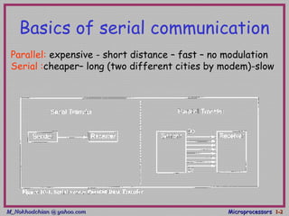
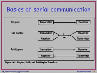
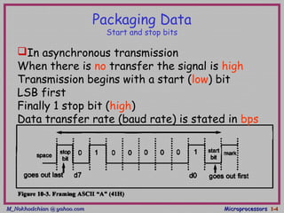
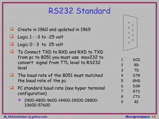
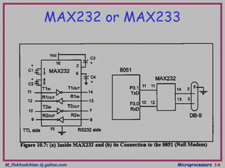
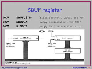
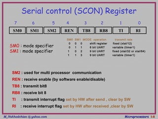
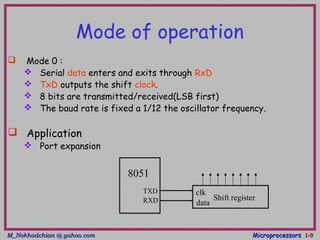
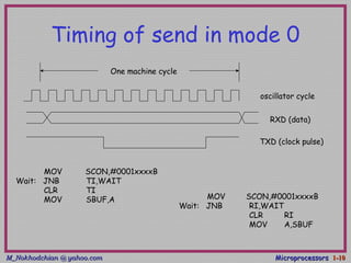
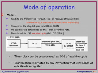
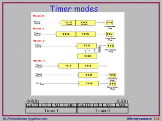
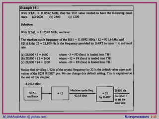
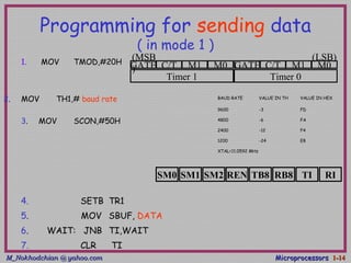
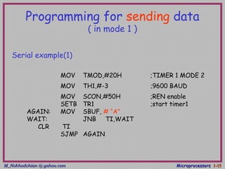
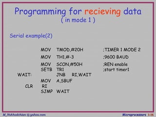
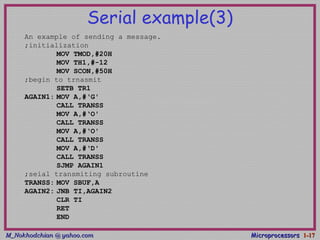
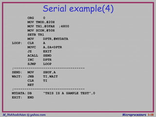
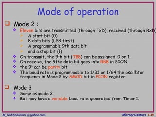
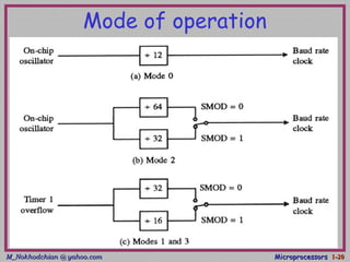
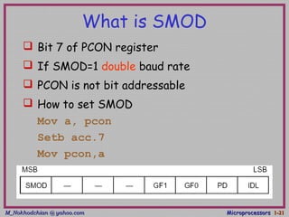
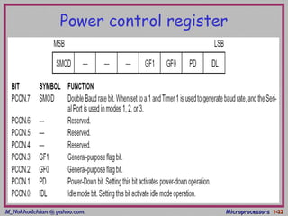
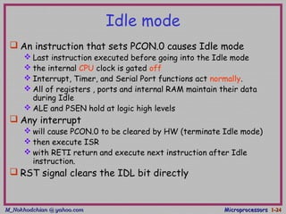
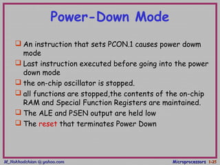
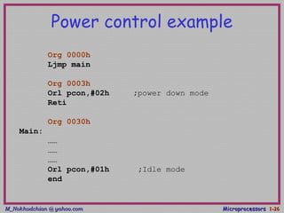
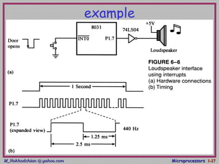
2. M_Nokhodchian @ yahoo.comM_Nokhodchian @ yahoo.com MicroprocessorsMicroprocessors 1-1-22
Basics of serial communication
Parallel: expensive - short distance – fast – no modulation
Serial :cheaper– long (two different cities by modem)-slow
4. M_Nokhodchian @ yahoo.comM_Nokhodchian @ yahoo.com MicroprocessorsMicroprocessors 1-1-44
Packaging Data
Start and stop bits
In asynchronous transmission
When there is no transfer the signal is high
Transmission begins with a start (low) bit
LSB first
Finally 1 stop bit (high)
Data transfer rate (baud rate) is stated in bps
5. M_Nokhodchian @ yahoo.comM_Nokhodchian @ yahoo.com MicroprocessorsMicroprocessors 1-1-55
RS232 Standard
Create in 1960 and updated in 1969
Logic 1 : -3 to -25 volt
Logic 0 : 3 to 25 volt
To Connect TXD to RXD and RXD to TXD
from pc to 8051 you must use max232 to
convert signal from TTL level to RS232
level
The baud rate of the 8051 must matched
the baud rate of the pc
PC standard baud rate (see hyper terminal
configuration)
2400-4800-9600-14400-19200-28800-
33600-57600
1 DCD
2 RD
3 TD
4 DTR
5 GND
6 DSR
7 RTS
8 CTS
9 RI
7. M_Nokhodchian @ yahoo.comM_Nokhodchian @ yahoo.com MicroprocessorsMicroprocessors 1-1-77
SBUF register
MOV SBUF,#’D’ ;load SBUF=44H, ASCII for ‘D’
MOV SBUF,A ;copy accumulator into SBUF
MOV A,SBUF ;copy SBUF into accumulator
8. M_Nokhodchian @ yahoo.comM_Nokhodchian @ yahoo.com MicroprocessorsMicroprocessors 1-1-88
Serial control (SCON) Register
SM2 : used for multi processor communication
REN : receive enable (by software enable/disable)
TB8 : transmit bit8
RB8 : receive bit 8
TI : transmit interrupt flag set by HW after send , clear by SW
RI : receive interrupt flag set by HW after received ,clear by SW
SM0 RITIRB8TB8RENSM2SM1
7 6 5 4 3 2 1 0
SM0 SM1 MODE operation transmit rate
0 0 0 shift register fixed (xtal/12)
0 1 1 8 bit UART variable (timer1)
1 0 2 9 bit UART fixed (xtal/32 or xtal/64)
1 1 3 9 bit UART variable (timer1)
SM0 : mode specifier
SM1 : mode specifier
9. M_Nokhodchian @ yahoo.comM_Nokhodchian @ yahoo.com MicroprocessorsMicroprocessors 1-1-99
Mode of operation
Mode 0 :
Serial data enters and exits through RxD
TxD outputs the shift clock.
8 bits are transmitted/received(LSB first)
The baud rate is fixed a 1/12 the oscillator frequency.
Application
Port expansion
8051
TXD
RXD Shift register
clk
data
10. M_Nokhodchian @ yahoo.comM_Nokhodchian @ yahoo.com MicroprocessorsMicroprocessors 1-1-1010
Timing of send in mode 0
One machine cycle
oscillator cycle
RXD (data)
TXD (clock pulse)
MOV SCON,#0001xxxxB
Wait: JNB RI,WAIT
CLR RI
MOV A,SBUF
MOV SCON,#0001xxxxB
Wait: JNB TI,WAIT
CLR TI
MOV SBUF,A
11. M_Nokhodchian @ yahoo.comM_Nokhodchian @ yahoo.com MicroprocessorsMicroprocessors 1-1-1111
Mode of operation
Mode 1
Ten bits are transmitted (through TxD) or received (through RxD)
(A start bit (0), 8 data bits (LSB first), and a stop bit (1) )
On receive, the stop bit goes into RB8 in SCON
the baud rate is determined by the Timer 1 overflow rate.
Timer1 clock is 1/32 machine cycle (MC=1/12 XTAL)
• Timer clock can be programmed as 1/16 of machine cycle
• Transmission is initiated by any instruction that uses SBUF as
a destination register.
14. M_Nokhodchian @ yahoo.comM_Nokhodchian @ yahoo.com MicroprocessorsMicroprocessors 1-1-1414
Programming for sending data
( in mode 1 )
4. SETB TR1
5. MOV SBUF, DATA
6. WAIT: JNB TI,WAIT
7. CLR TI
GATE C/T M1 M0 GATE C/T M1 M0
Timer 1 Timer 0
(MSB
)
(LSB)1. MOV TMOD,#20H
2. MOV TH1,# baud rate BAUD RATE VALUE IN TH VALUE IN HEX
9600 -3 FD
4800 -6 FA
2400 -12 F4
1200 -24 E8
XTAL=11.0592 MHz
3. MOV SCON,#50H
SM0 RITIRB8TB8RENSM2SM1
15. M_Nokhodchian @ yahoo.comM_Nokhodchian @ yahoo.com MicroprocessorsMicroprocessors 1-1-1515
Programming for sending data
( in mode 1 )
MOV TMOD,#20H ;TIMER 1 MODE 2
MOV TH1,#-3 ;9600 BAUD
MOV SCON,#50H ;REN enable
SETB TR1 ;start timer1
AGAIN: MOV SBUF, # “A”
WAIT: JNB TI,WAIT
CLR TI
SJMP AGAIN
Serial example(1)
16. M_Nokhodchian @ yahoo.comM_Nokhodchian @ yahoo.com MicroprocessorsMicroprocessors 1-1-1616
Programming for recieving data
( in mode 1 )
MOV TMOD,#20H ;TIMER 1 MODE 2
MOV TH1,#-3 ;9600 BAUD
MOV SCON,#50H ;REN enable
SETB TR1 ;start timer1
WAIT: JNB RI,WAIT
MOV A,SBUF
CLR RI
SJMP WAIT
Serial example(2)
17. M_Nokhodchian @ yahoo.comM_Nokhodchian @ yahoo.com MicroprocessorsMicroprocessors 1-1-1717
Serial example(3)
An example of sending a message.
;initialization
MOV TMOD,#20H
MOV TH1,#-12
MOV SCON,#50H
;begin to trnasmit
SETB TR1
AGAIN1: MOV A,#‘G'
CALL TRANSS
MOV A,#‘O'
CALL TRANSS
MOV A,#‘O'
CALL TRANSS
MOV A,#‘D'
CALL TRANSS
SJMP AGAIN1
;seial transmiting subroutine
TRANSS: MOV SBUF,A
AGAIN2: JNB TI,AGAIN2
CLR TI
RET
END
18. M_Nokhodchian @ yahoo.comM_Nokhodchian @ yahoo.com MicroprocessorsMicroprocessors 1-1-1818
Serial example(4)
ORG 0
MOV TMOD,#20H
MOV TH1,#0FAH ;4800
MOV SCON,#50H
SETB TR1
MOV DPTR,#MYDATA
LOOP: CLR A
MOVC A,@A+DPTR
JZ EXIT
ACALL SEND
INC DPTR
SJMP LOOP
;----------------------------------
SEND: MOV SBUF,A
WAIT: JNB TI,WAIT
CLR TI
RET
;----------------------------------
MYDATA: DB “THIS IS A SAMPLE TEST”,0
EXIT: END
19. M_Nokhodchian @ yahoo.comM_Nokhodchian @ yahoo.com MicroprocessorsMicroprocessors 1-1-1919
Mode of operation
Mode 2 :
Eleven bits are transmitted (through TxD), received (through RxD)
A start bit (0)
8 data bits (LSB first)
A programmable 9th data bit
and a stop bit (1)
On transmit, the 9th bit (TB8) can be assigned 0 or 1.
On receive, the 9the data bit goes into RB8 in SCON.
the 9th
can be parity bit
The baud rate is programmable to 1/32 or 1/64 the oscillator
frequency in Mode 2 by SMOD bit in PCON register
Mode 3
Same as mode 2
But may have a variable baud rate generated from Timer 1.
21. M_Nokhodchian @ yahoo.comM_Nokhodchian @ yahoo.com MicroprocessorsMicroprocessors 1-1-2121
What is SMOD
Bit 7 of PCON register
If SMOD=1 double baud rate
PCON is not bit addressable
How to set SMOD
Mov a, pcon
Setb acc.7
Mov pcon,a
23. M_Nokhodchian @ yahoo.comM_Nokhodchian @ yahoo.com MicroprocessorsMicroprocessors 1-1-2323
Power control
A standard for applications where power
consumption is critical
two power reducing modes
Idle
Power down
24. M_Nokhodchian @ yahoo.comM_Nokhodchian @ yahoo.com MicroprocessorsMicroprocessors 1-1-2424
Idle mode
An instruction that sets PCON.0 causes Idle mode
Last instruction executed before going into the Idle mode
the internal CPU clock is gated off
Interrupt, Timer, and Serial Port functions act normally.
All of registers , ports and internal RAM maintain their data
during Idle
ALE and PSEN hold at logic high levels
Any interrupt
will cause PCON.0 to be cleared by HW (terminate Idle mode)
then execute ISR
with RETI return and execute next instruction after Idle
instruction.
RST signal clears the IDL bit directly
25. M_Nokhodchian @ yahoo.comM_Nokhodchian @ yahoo.com MicroprocessorsMicroprocessors 1-1-2525
Power-Down Mode
An instruction that sets PCON.1 causes power dowm
mode
Last instruction executed before going into the power
down mode
the on-chip oscillator is stopped.
all functions are stopped,the contents of the on-chip
RAM and Special Function Registers are maintained.
The ALE and PSEN output are held low
The reset that terminates Power Down
26. M_Nokhodchian @ yahoo.comM_Nokhodchian @ yahoo.com MicroprocessorsMicroprocessors 1-1-2626
Power control example
Org 0000h
Ljmp main
Org 0003h
Orl pcon,#02h ;power down mode
Reti
Org 0030h
Main:
……
……
……
Orl pcon,#01h ;Idle mode
end