5. Why UART is still used?
Interfacing using USB
UART Uses
6. Communication between electronic devices
is like communication between humans. Both
sides need to speak the same language. In
electronics, these languages are
called communication protocols. Luckily for
us, there are only a few communication
protocols we need to know.
7. UART stands for Universal Asynchronous
Receiver/Transmitter.
It’s not a communication protocol like SPI
and I2C,but a physical circuit in
microcontroller, or a stand-alone IC.
It is a computer hardware device for
asynchronous serial communication in which
data format and transmission speeds are
configurable.
8. A UART’s main purpose is to transmit and receive
serial data.
One of the best things about UART is that it only
uses two wires to transmit data between devices
9. A UART may be used when:-
High speed is not required
An inexpensive communication link between
two devices is required.
UART communication is very cheap:-
Single wire for each direction(and ground
wire).
Simple hardware.
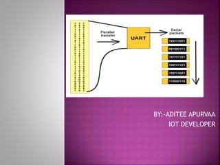
10. In UART communication, two UARTs
communicate directly with each other.
The transmitting UART converts parallel data
from a controlling device like a CPU into
serial form, transmits it in serial to the
receiving UART, which then converts the
serial data back into parallel data for the
receiving device.
11. The UART that is going to transmit data
receives the data from a data bus. The data
bus is used to send data to the UART by
another device like a CPU, memory, or
microcontroller. Data is transferred from the
data bus to the transmitting UART in parallel
form. After the transmitting UART gets
the parallel data from the data bus, it adds a
start bit, a parity bit, and a stop bit, creating
the data packet.
12. Next, the data packet is output serially, bit
by bit at the Tx pin. The receiving UART
reads the data packet bit by bit at its Rx pin.
The receiving UART then converts the data
back into parallel form and removes the start
bit, parity bit, and stop bits. Finally, the
receiving UART transfers the data packet in
parallel to the data bus on the receiving end.
13.
14.
15. When the receiving UART detects a start
bit, it starts to read the incoming bits at a
specific frequency known as the baud
rate. Baud rate is a measure of the speed of
data transfer, expressed in bits per second
(bps).
Both UARTs must operate at about the same
baud rate. The baud rate between the
transmitting and receiving UARTs can only
differ by about 10% before the timing of bits
gets too far off.
16.
17. START BIT
The UART data transmission line is normally
held at a high voltage level when it’s
not transmitting data.
To start the transfer of data, the transmitting
UART pulls the transmission line from high to
low for one clock cycle.
When the receiving UART detects the high to
low voltage transition, it begins reading the
bits in the data frame at the frequency of
the baud rate.
18. DATA FRAME
The data frame contains the actual data
being transferred. It can be 5 bits up to 8
bits long if a parity bit is used.
If no parity bit is used, the data frame can
be 9 bits long. In most cases, the data is sent
with the least significant bit first.
19. PARITY
Parity describes the evenness or oddness of a
number.
The parity bit is a way for the receiving UART
to tell if any data has changed during
transmission(Bits can be changed
by electromagnetic radiation, mismatched
baud rates, or long distance data transfers).
After the receiving UART reads the data
frame, it counts the number of bits with a
value of 1 and checks if the total is an even
or odd number.
20. If the parity bit is a 0 (even parity), the 1
bits in the data frame should total to an even
number. If the parity bit is a 1 (odd parity),
the 1 bits in the data frame should total to
an odd number.
When the parity bit matches the data, the
UART knows that the transmission was free of
errors. But if the parity bit is a 0, and the
total is odd; or the parity bit is a 1, and the
total is even, the UART knows that bits in the
data frame have changed.
21. STOP BITS
To signal the end of the data packet, the
sending UART drives the data transmission
line from a low voltage to a high voltage for
at least two bit durations.
Receiver
All operations of the UART hardware are
controlled by a clock signal which runs at a
multiple of the data rate, typically 8 times
the bit rate.
The receiver tests the state of the incoming
signal on each clock pulse, looking for the
beginning of the start bit.
22. If the apparent start bit lasts at least one-
half of the bit time, it is valid and signals the
start of a new character.
If not, it is considered a spurious pulse and
is ignored. After waiting a further bit time,
the state of the line is again sampled and the
resulting level clocked into a shift register.
After the required number of bit periods for
the character length (5 to 8 bits, typically)
have elapsed, the contents of the shift
register are made available (in parallel
fashion) to the receiving system.
23. The UART will set a flag indicating new data
is available, and may also generate a
processor interrupt to request that the host
processor transfers the received data.
Communicating UARTs usually have no shared
timing system apart from the communication
signal.
Typically, UARTs resynchronize their internal
clocks on each change of the data line that is
not considered a spurious pulse
24. Obtaining timing information in this manner,
they reliably receive when the transmitter is
sending at a slightly different speed than it
should. Simplistic UARTs do not do this,
instead they resynchronize on the falling
edge of the start bit only, and then read the
center of each, expected data bit, and this
system works if the broadcast data rate is
accurate enough to allow the stop bits to be
sampled reliably.
25. It is a standard feature for a UART to store
the most recent character while receiving
the next. This "double buffering" gives a
receiving computer an entire character
transmission time to fetch a received
character. Many UARTs have a small first-in,
first-out FIFO buffer memory between the
receiver shift register and the host system
interface. This allows the host processor
even more time to handle an interrupt from
the UART and prevents loss of received data
at high rates.
26. Transmitter
Transmission operation is simpler as the timing
does not have to be determined from the line
state, nor is it bound to any fixed timing
intervals.
As soon as the sending system deposits a
character in the shift register (after completion
of the previous character), the UART generates a
start bit, shifts the required number of data bits
out to the line, generates and sends the parity
bit (if used), and sends the stop bits.
Since full-duplex operation requires characters
to be sent and received at the same time, UARTs
use two different shift registers for transmitted
and received characters.
27. High performance UARTs could contain a
transmit FIFO (first in first out) buffer to
allow a CPU or DMA controller to deposit
multiple characters in a burst into the FIFO
rather than have to deposit one character at
a time into the FIFO.
Since transmission of a single or multiple
characters may take a long time relative to
CPU speeds, a UART maintains a flag showing
busy status so that the host system knows if
there is at least one character in the
transmit buffer or shift register; "ready for
next character(s)" may also be signaled with
an interrupt.
29. The transmitting UART adds the start bit,
parity bit, and the stop bit(s) to the data
frame:
30. The entire packet is sent serially from the
transmitting UART to the receiving UART. The
receiving UART samples the data line at the
pre-configured baud rate:
31. The receiving UART discards the start bit,
parity bit, and stop bit from the data frame:
32. The receiving UART converts the serial data
back into parallel and transfers it to the data
bus on the receiving end:
33. So far, we have discussed the software
protocol of the UART. How about the physical
layer standards? There are actually quite a
number of different standards that utilizes
similar protocol. For instances, TTL level
UART, RS-232, RS-422, RS-485 and etc. We
will only discuss about TTL level UART and
RS-232 here.
34. Most microcontrollers with UART uses TTL
(Transistor-transistor Logic) level UART. It is
the simplest form of UART. Both logic 1 and 0
are represented by 5V and 0V respectively.
LOGIC VOLTAGE
LOW 0V
HIGH 5V
35. The TTL level UART is commonly used in the
communications between microcontrollers
and ICs. Only 2 wires are required for the full
duplex communications as illustrated in the
picture below.
36. RS-232 (Recommended Standard 232) is a
standard for serial binary data signals
connecting between a Data Terminal
Equipment (DTE) and a Data Communication
Equipment (DCE). It is commonly used in
computer serial ports. One of the significant
differences between TTL level UART and RS-
232 is the voltage level. Valid signals in RS-
232 are ±3 to – ±15V, and signals near 0V is
not a valid RS-232 level.
38. RS-232 voltage level for data 0X4B with 1
start bit,8 data bits and 1 stop bit.
39. Besides voltage level, the RS-232 also has a
few extra pins specifically designed for the
communication between PC and modem. The
pinouts of the DB-9 and their functions are
shown below.
40.
41. NAME DESCRIPTION
DCD Asserted by DCE when a
connection has been
established with remote
equipment.
RxD Serial Data Input.
TxD Serial Data Output.
DTR Asserted by DTE to indicate
that it is ready to be
connected.
DSR Asserted by DCE to indicate that
DCE is powered on and is ready to
receive commands or data for
transmission from DTE
42. NAME DESCRIPTION
RTS This line informs the
DCE(Modem) that the
DTE(PC) is ready to
exchange data.
CTS This line indicates that
DCE is ready to exchange
data.
RI Asserted by DCE when it
detects a ring signal from
the telephone line.
43. When RS232 was developed the idea was that
there would be 2 kinds of devices, DTE (Data
Terminal Equipment) and DCE (Data
Communications Equipment). Everything
would use DB25 connectors and everyone
would always connect a DTE to a DCE using a
straight-through cable and everything would
be easy.
However, as time went by folks wanted to
connect two DTEs (or two DCEs) to each
other, and DB9 connectors started being
used, so alternative cable wirings were
required.
44. There are no hard and fast rules but in
general a DTE will have a male DB25 or
possibly a male DB9 connector and a DCE will
have a female DB25 or DB9. Other
connectors may be used but these are the
most common.
A typical DTE is a serial port on a terminal, a
Com port on a PC or the serial port on an
MSS100.
A typical DCE is the serial port on a modem
or on a UDS-10, UDS100 or UDS1100.
45. From previous discussions, we know that
microcontrollers make use of TTL level UART
while the PC serial port uses RS-232. Since
both standards uses similar software
protocol, both of them are able to
communicate via UART. However, because of
the differences in voltage level and polarity,
we will need a level shifter to interface the
TTL level UART with the RS-232. Nowadays,
this can be easily done with the commonly
available IC such as the MAX232 from Maxim.
46.
47. Overrun error
An "overrun error" occurs when the receiver
cannot process the character that just came in
before the next one arrives. Various devices have
different amounts of buffer space to hold
received characters.
The CPU or DMA controller must service the
UART in order to remove characters from the
input buffer. If the CPU or DMA controller does
not service the UART quickly enough and the
buffer becomes full, an Overrun Error will occur,
and incoming characters will be lost.
48. Underrun error
An "underrun error" occurs when the UART
transmitter has completed sending a
character and the transmit buffer is empty.
In asynchronous modes this is treated as an
indication that no data remains to be
transmitted, rather than an error, since
additional stop bits can be appended.
This error indication is commonly found in
USARTs, since an underrun is more serious in
synchronous systems.
49. Framing error
A "framing error" occurs when the designated
"start" and "stop" bits are not found.
As the "start" bit is used to identify the
beginning of an incoming character, it acts as
a reference for the remaining bits.
If the data line is not in the expected state
(hi/lo) when the "stop" bit is expected,
a Framing Error will occur.
50. Parity error
A Parity Error occurs when the parity of the
number of 1 bits disagrees with that
specified by the parity bit.
Use of a parity bit is optional, so this error
will only occur if parity-checking has been
enabled.
51. Break condition
A "break condition" occurs when the receiver
input is at the "space" (logic low, i.e., '0')
level for longer than some duration of time,
typically, for more than a character time.
This is not necessarily an error, but appears
to the receiver as a character of all zero bits
with a framing error.
The term "break" derives from current
loop signaling, which was the traditional
signaling used for teletypewriters. The
"spacing" condition of a current loop line is
indicated by no current flowing, and a very
long period of no current flowing is often
caused by a break or other fault in the line.
52. Some equipment will deliberately transmit
the "space" level for longer than a character
as an attention signal. When signaling rates
are mismatched, no meaningful characters
can be sent, but a long "break" signal can be
a useful way to get the attention of a
mismatched receiver to do something (such
as resetting itself). Unix-like systems can use
the long "break" level as a request to change
the signaling rate, to support dial-in access
at multiple signaling rates.
53. An embedded system often requires a means
for communicating with the external world
for a number of possible reasons.
It could be to transferring data to another
device, sending and receiving commands, or
simply for debugging purposes. One of the
most common interfaces used in embedded
systems is the universal asynchronous
receiver/transmitter (UART).
When a board arrives in the hands of the
software/firmware team, the first step is
typically to get the debug console functional.
54. The debug console is a serial interface which
historically is implemented as RS-232 to
connect with a PC serial port.
A way is required to interact with the board
untethered. A console is required,and that
means the UART. It requires no additional
stack of software other than poking at a few
configuration registers.
The serial async protocol is simple enough
that it’s decodable by eyeball, in a pinch.
55. UART is used for various purposes in
embedded:-
For interacting with console - Like displaying
debug messages.
Sending few commands from connected
terminal
Loading the firmware
Loading the applications
Few device interfaces like GSM, Bluetooth or
Camera controllers are connected to main
board via UART bus.
56. Like Data can be collected to Memory
directly via DMA, but comman and contol
messages are sent to these devices using
UART interface.
These is the reason few Embedded Boards
has more than one UART interface on the
boards
57. Is IOT ignoring UART?
IoT doesn't ignore RS-232 at all. Almost all of the
tiniest devices have 3 pads exposed for a
TxD/RxD/GND of a 3.3V "RS-232" signal. But the idea
that you have to add an additional device (in IoT
parlance, a "gateway") to network a device is
wasteful and silly.
RS-232 is low speed and serial, which makes it
perfectly suitable for a lot of tasks where there is a
low data rate. It's point to point which means you'll
need wires from your peripheral to the controller.
58. Technically, large scale IoT will be probably be
cooperating low-power wireless mesh networks.
The functionality will be implemented in a sliver
of silicon which is part of a SoC, like most RS-232
connections are these days.
Rather than having to bolt a network on to the
RS-232 link, a tiny sliver of an antenna will pop
out from the chip, likely part of the PCB.
The SoC will directly integrate into a low power
wireless network from the IEEE 802.15.4family or
similar low power, short-range technologies.
59. In the IETF, the RTG/ROLL working group
develops standards to interconnect this
staggering volume of low traffic devices.
So, RS-232 is not being ignored. It just won't
scale to the grander vision of IoT.
60. ADVANTAGES
Only uses two wires
No clock signal is necessary
Has a parity bit to allow for error checking
The structure of the data packet can be
changed as long as both sides are set up for
it
Well documented and widely used method
61. DISADVANTAGES
The size of the data frame is limited to a
maximum of 9 bits
Doesn’t support multiple slave or multiple
master systems
The baud rates of each UART must be within
10% of each other
62. A common serial port, the kind with TX and
RX lines, is called “asynchronous” (not
synchronous) because there is no control
over when data is sent or any guarantee that
both sides are running at precisely the same
rate.
Since computers normally rely on everything
being synchronized to a single “clock” (the
main crystal attached to a computer that
drives everything), this can be a problem
when two systems with slightly different
clocks try to communicate with each other.
63. To work around this problem, asynchronous
serial connections add extra start and stop
bits to each byte help the receiver sync up to
data as it arrives.
64. Both sides must also agree on the transmission
speed (such as 9600 bits per second) in advance.
Slight differences in the transmission rate aren’t
a problem because the receiver re-syncs at the
start of each byte.
Asynchronous serial works just fine, but has a lot
of overhead in both the extra start and stop bits
sent with every byte, and the complex hardware
required to send and receive data. And as you’ve
probably noticed in your own projects, if both
sides aren’t set to the same speed, the received
data will be garbage. This is because the
receiver is sampling the bits at very specific
times (the arrows in the above diagram). If the
receiver is looking at the wrong times, it will see
the wrong bits.
65. UART is the simplest form of communication
between microcontroller and PC.
However, due to the mushrooming growth of
technology, serial port is slowly being
replaced by other means of communication
port.
Nevertheless, serial communication is still
possible even without a physical serial port
on your PC. For example, the USB can be
treated as a serial port after the signal from
microcontroller is converted using the USB to
RS-232 converter
66. In order to gain more understanding on this
converter, feel free to refer to the USB to
UART converter (UC00A) from Cytron as it is
a readily available device that provides
communication between UART and USB via
the USB to RS-232 converter.
67.
68.
69. PC serial port is a UART
Serializes data to be sent over a serial cable
De-serializes received data
Communication between distant computers
Serializes data to be sent to modem
De-serializes received data from modem
Used to be commonly used for internet
access
Used to be used for mainframe access, a
mainframe can have dozens of serial ports