Download to read offline


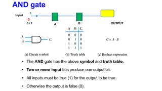
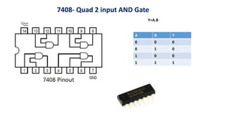
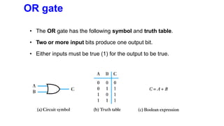
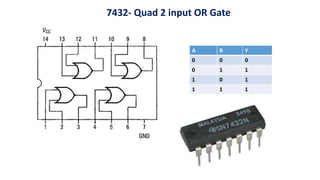
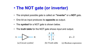
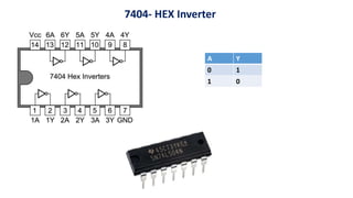
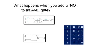
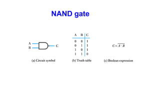
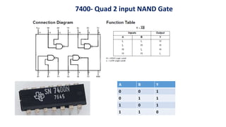
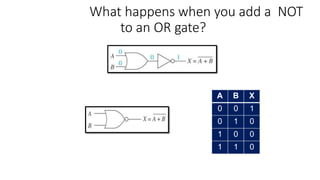
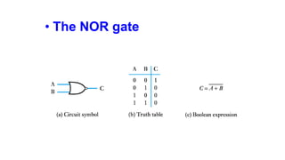
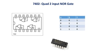
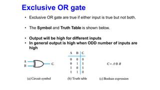
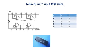
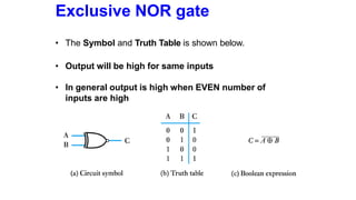
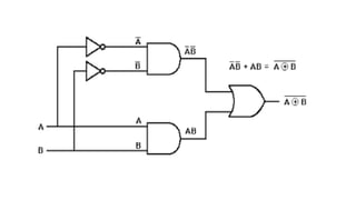
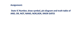

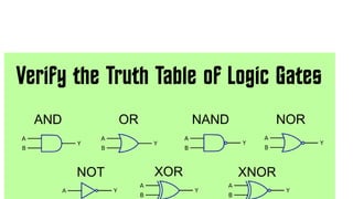


- The document discusses different logic gates - AND, OR, NOT, NAND, NOR, XOR, and XNOR - and provides their symbols, truth tables, and example integrated circuit (IC) numbers. - Logic gates take one or more binary inputs and produce a single binary output according to their truth tables. For example, the AND gate outputs 1 only if all inputs are 1, while the OR gate outputs 1 if any input is 1. - Common ICs for different logic gates are also provided, such as the 7400 quad NAND gate and 7486 quad XOR gate. - The document concludes by assigning students to state IC numbers, draw symbols, pin diagrams, and truth tables for the different logic