Downloaded 366 times


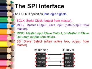
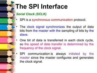
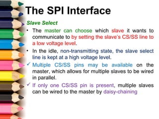

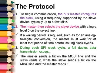

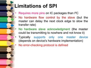
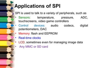

The Serial Peripheral Interface (SPI) is a synchronous serial communication protocol developed for short-distance connections, allowing full duplex data transmission and employing a master-slave architecture. SPI facilitates uninterrupted data transfer and operates with four key signals: serial clock (SCLK), master-out slave-in (MOSI), master-in slave-out (MISO), and slave select (SS). While SPI offers advantages like higher throughput and simplicity in device addressing, it requires more pins than other protocols like I2C and lacks inherent hardware acknowledgment or error-checking mechanisms.


![Communication_Protocols[2][1].pptx on protocoals](https://cdn.slidesharecdn.com/ss_thumbnails/communicationprotocols21-250429164707-38355411-thumbnail.jpg?width=640&height=640&fit=bounds)