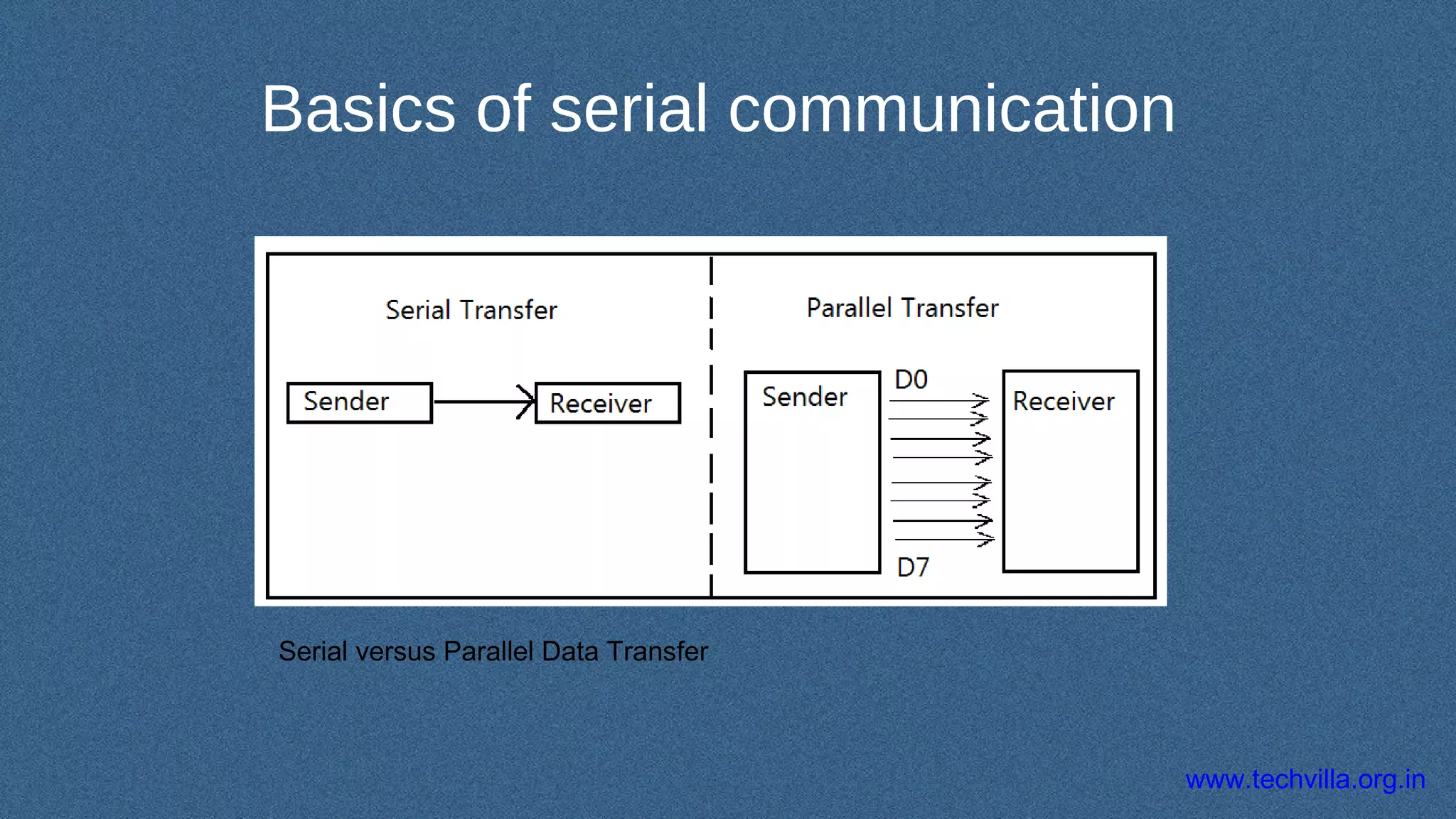
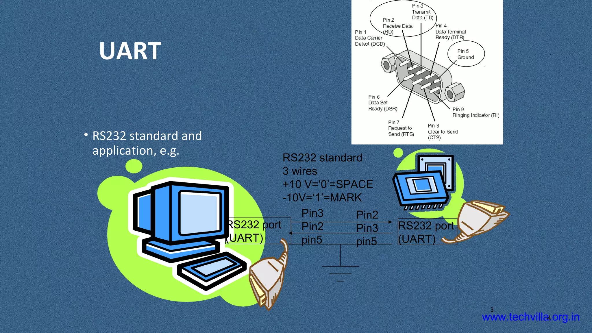
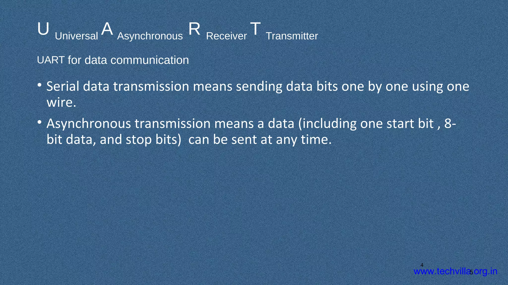
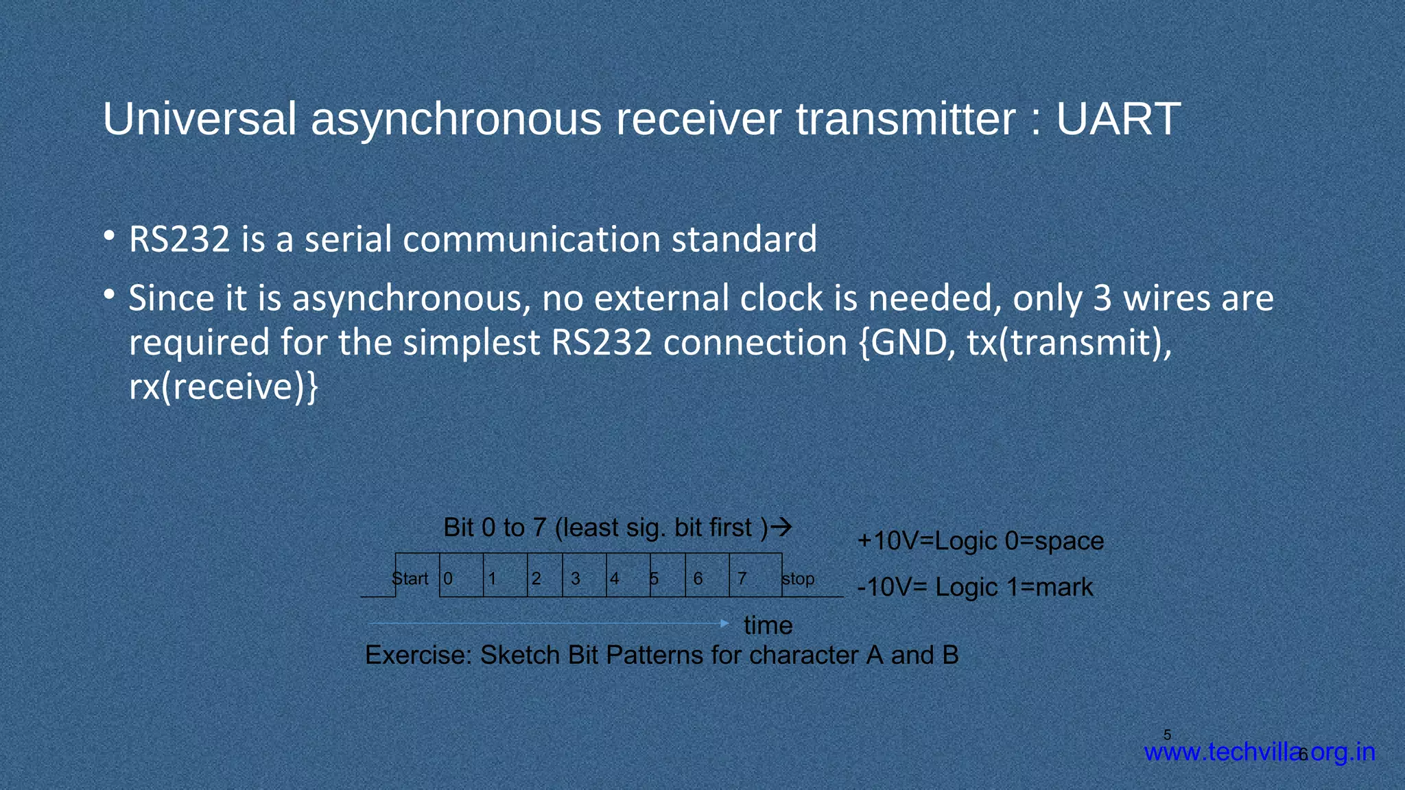
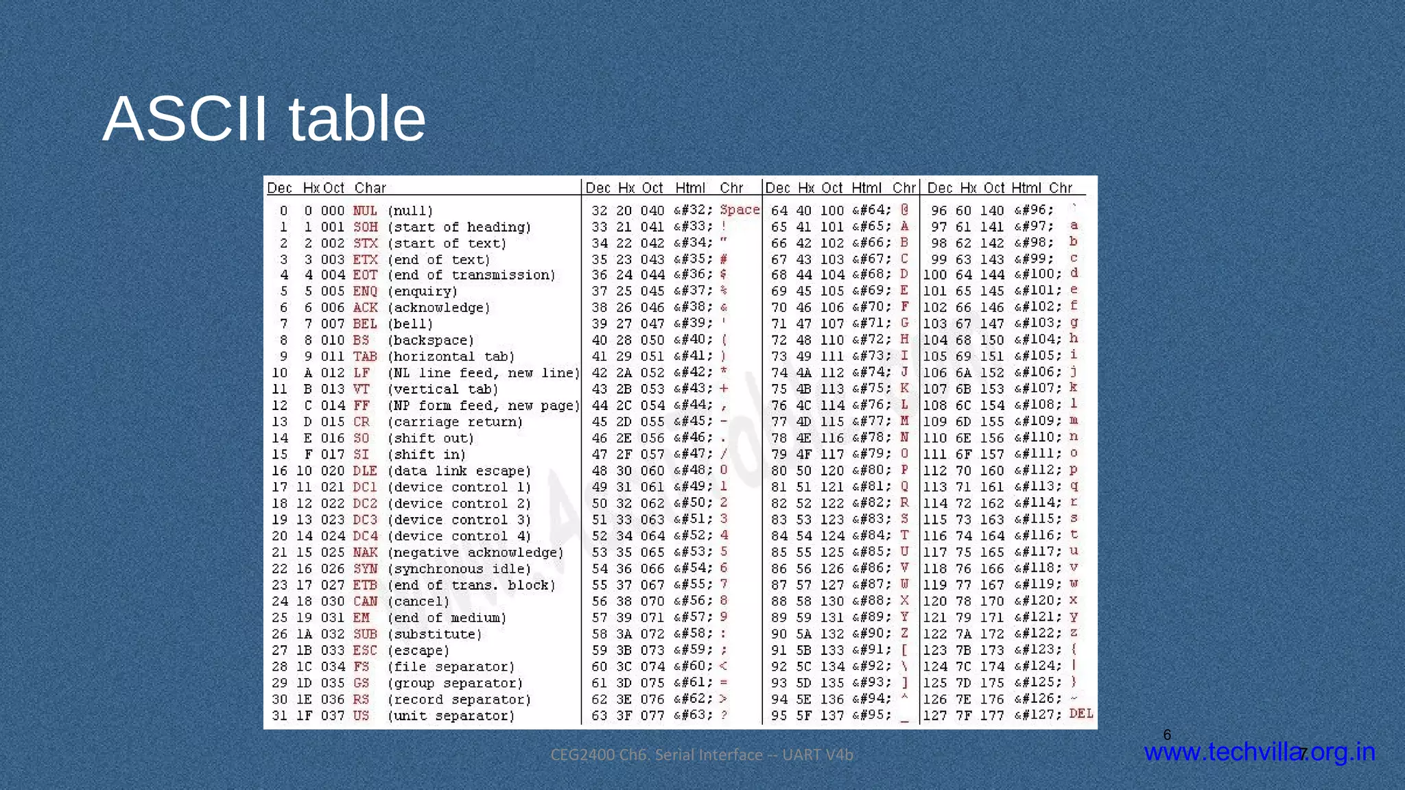
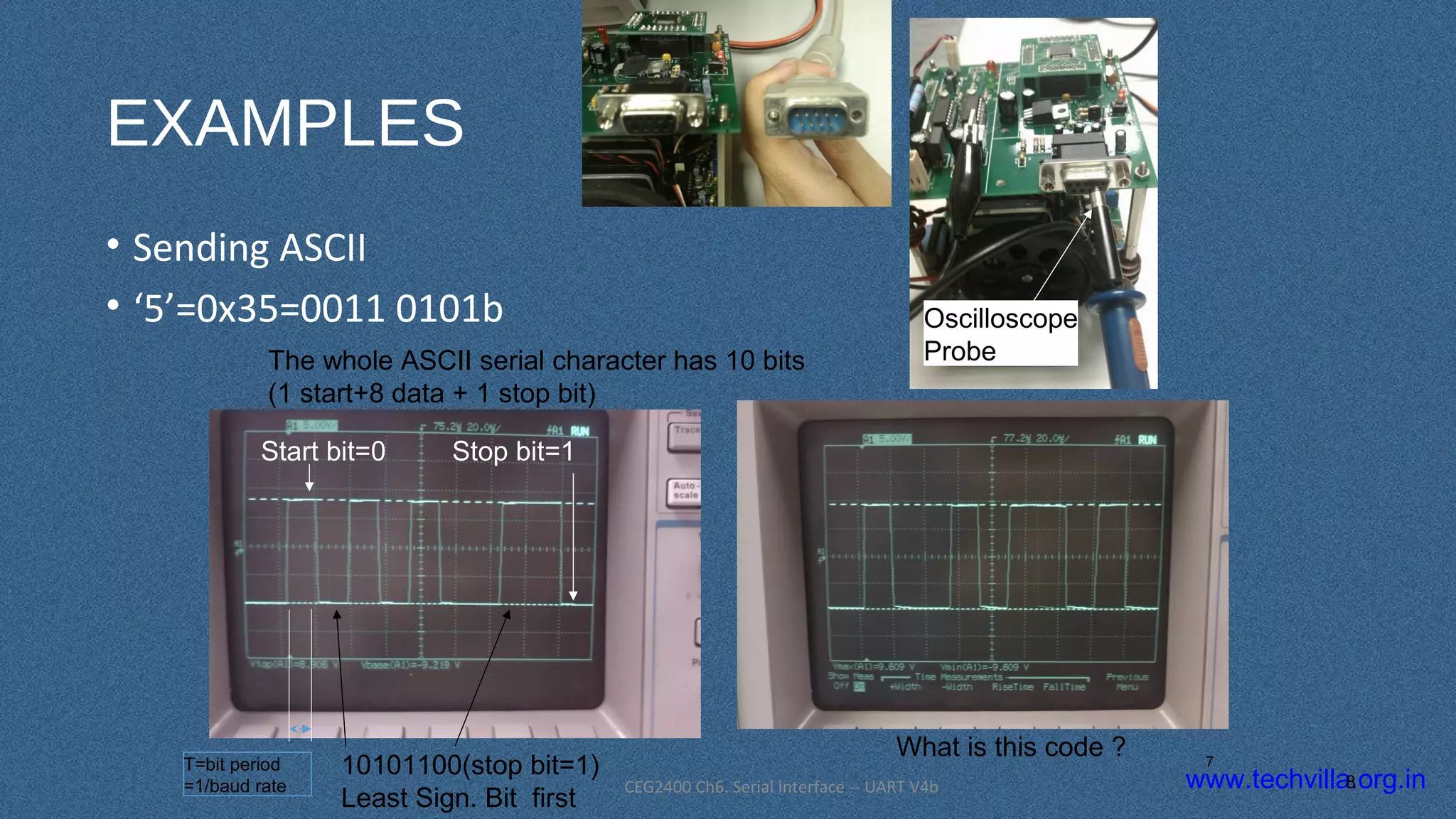
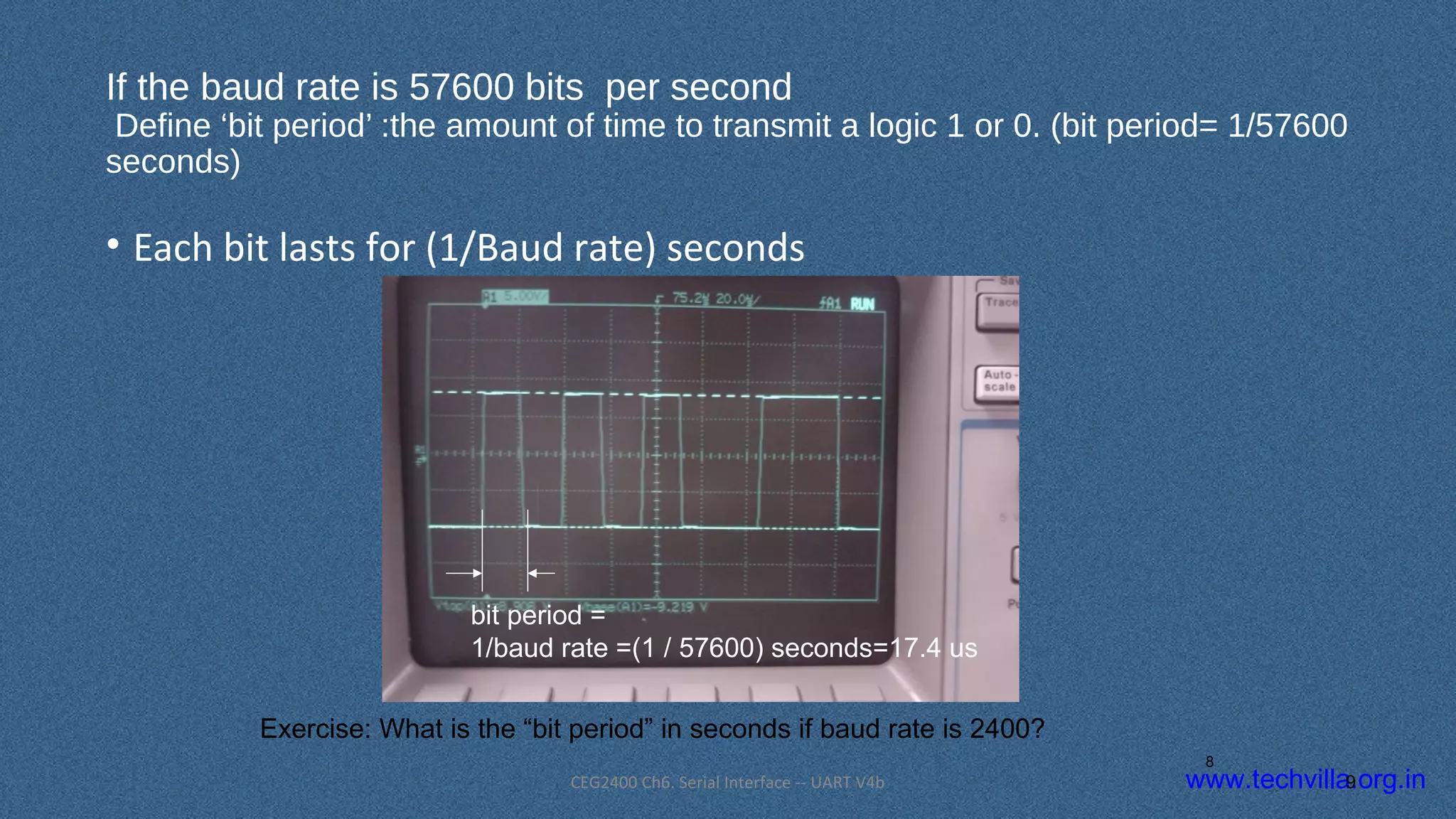
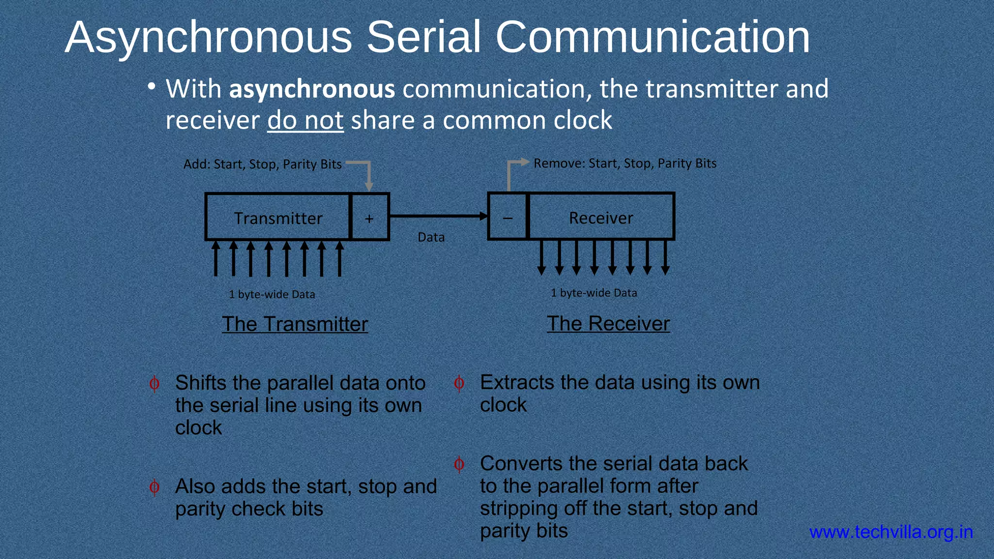
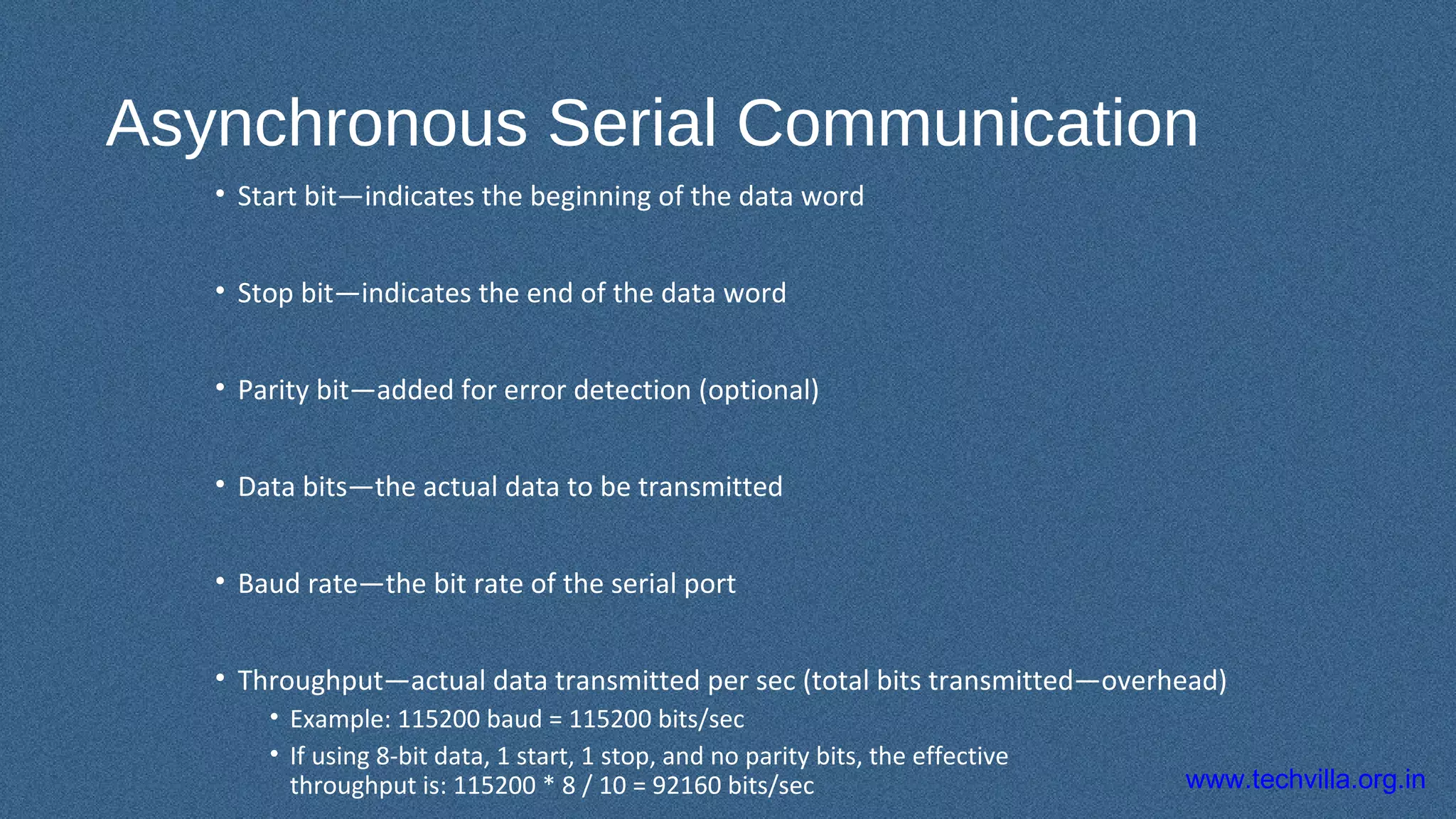
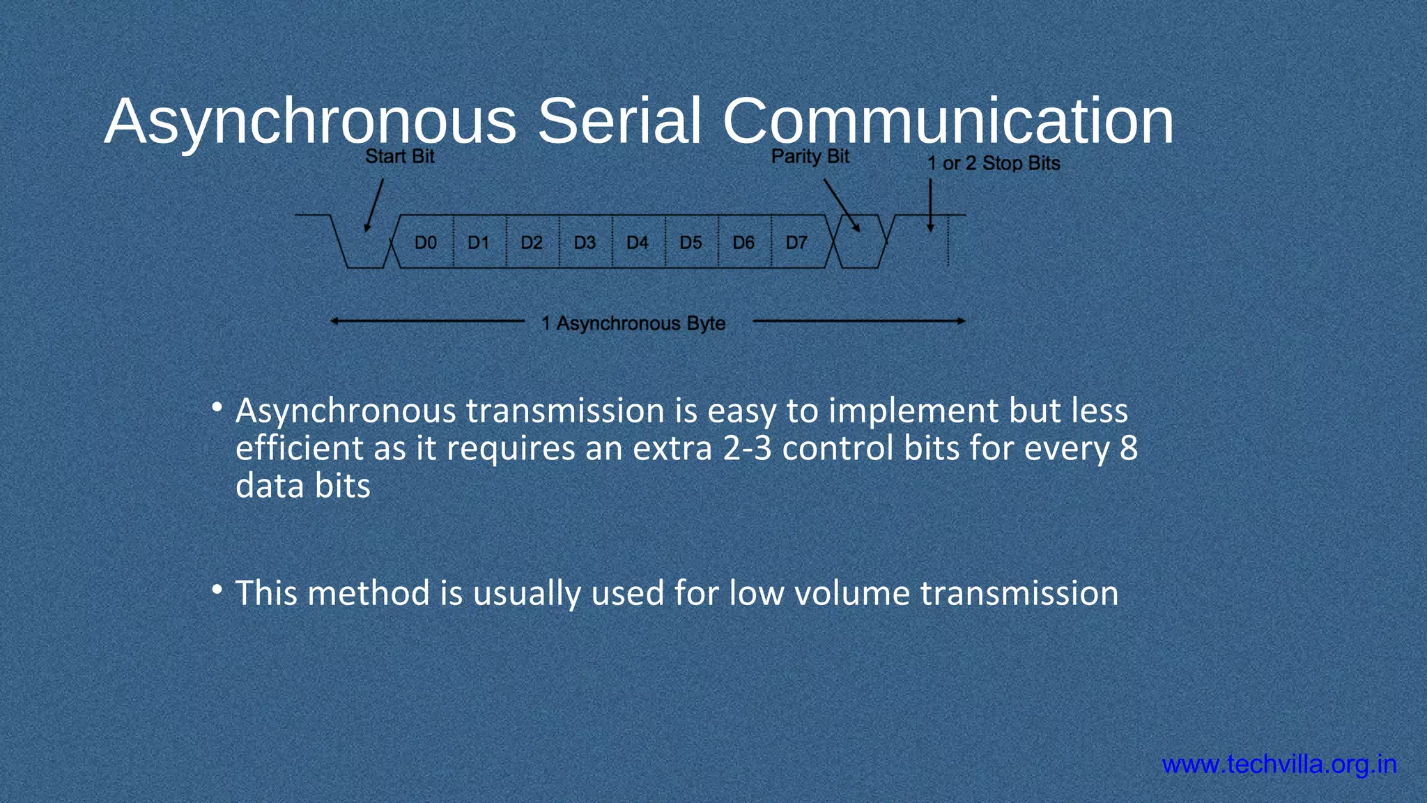
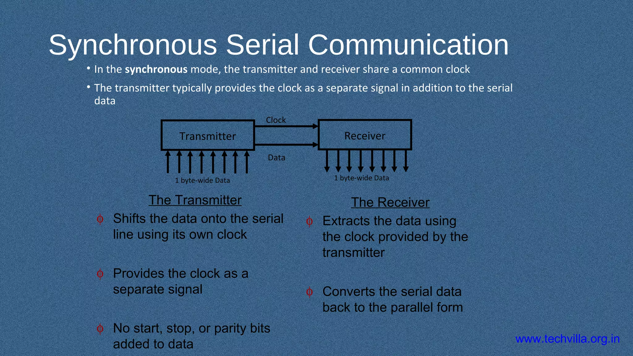
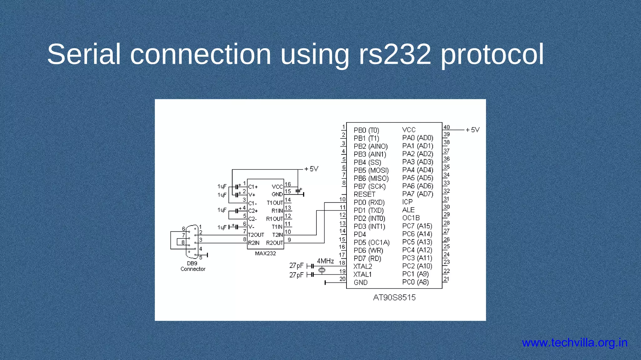
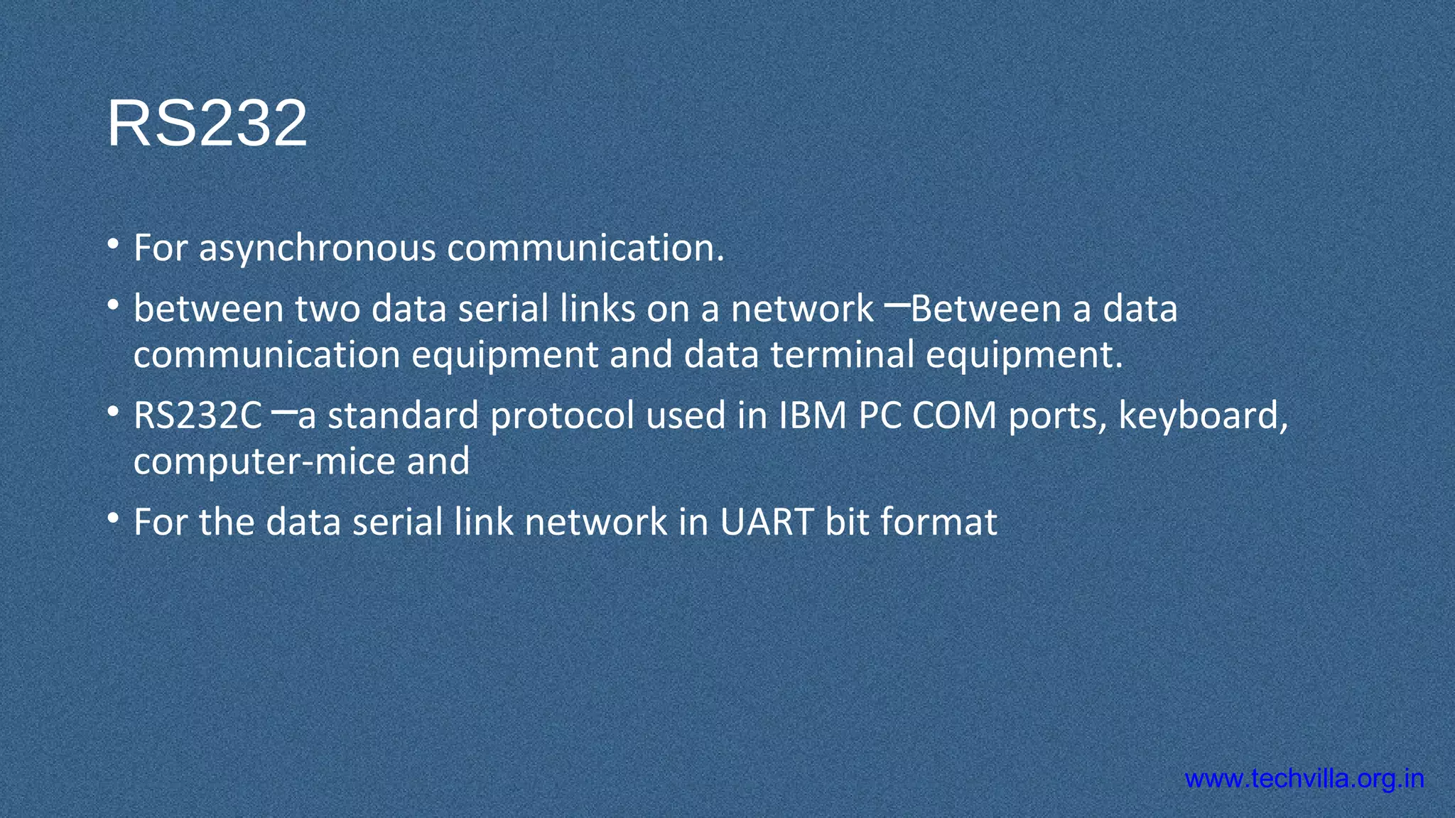
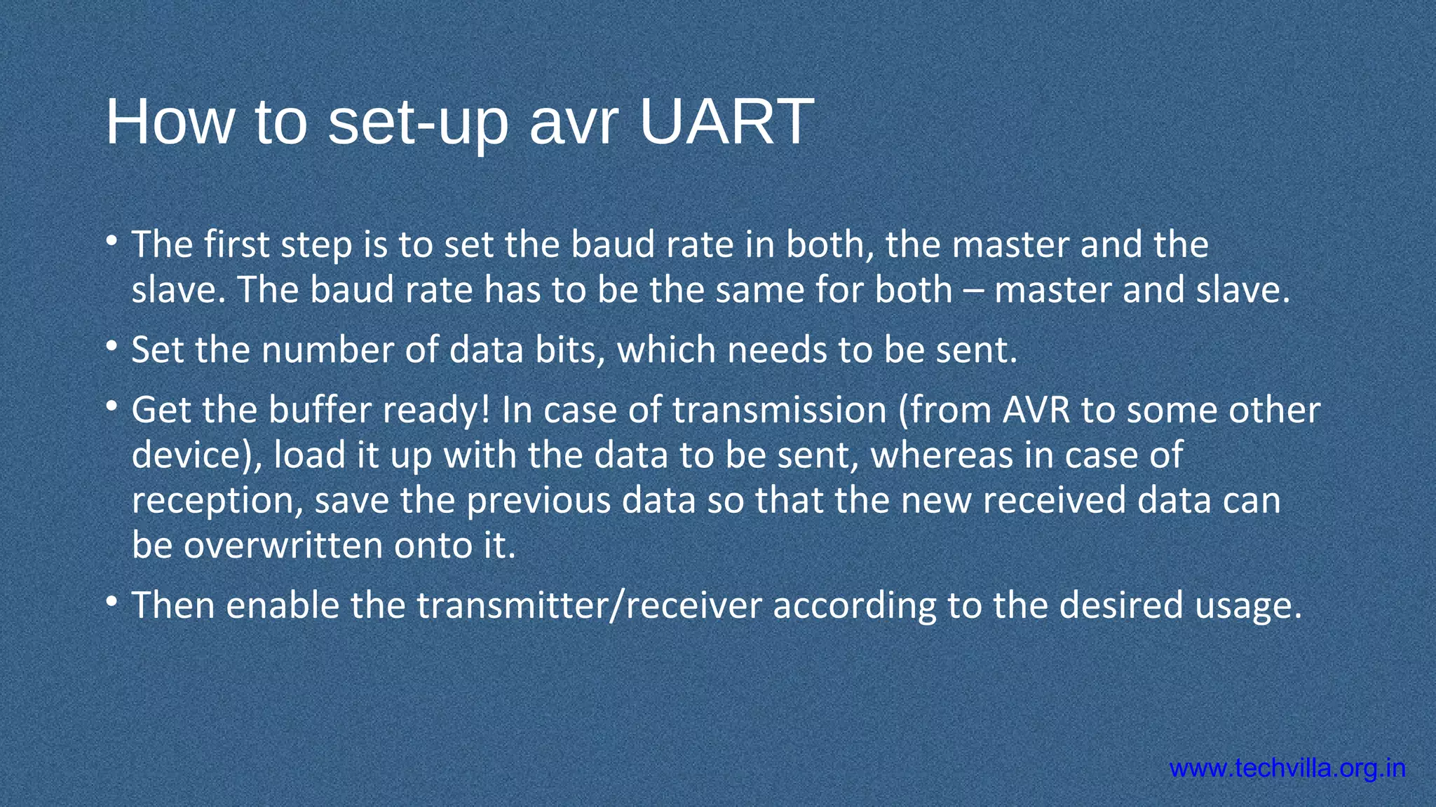
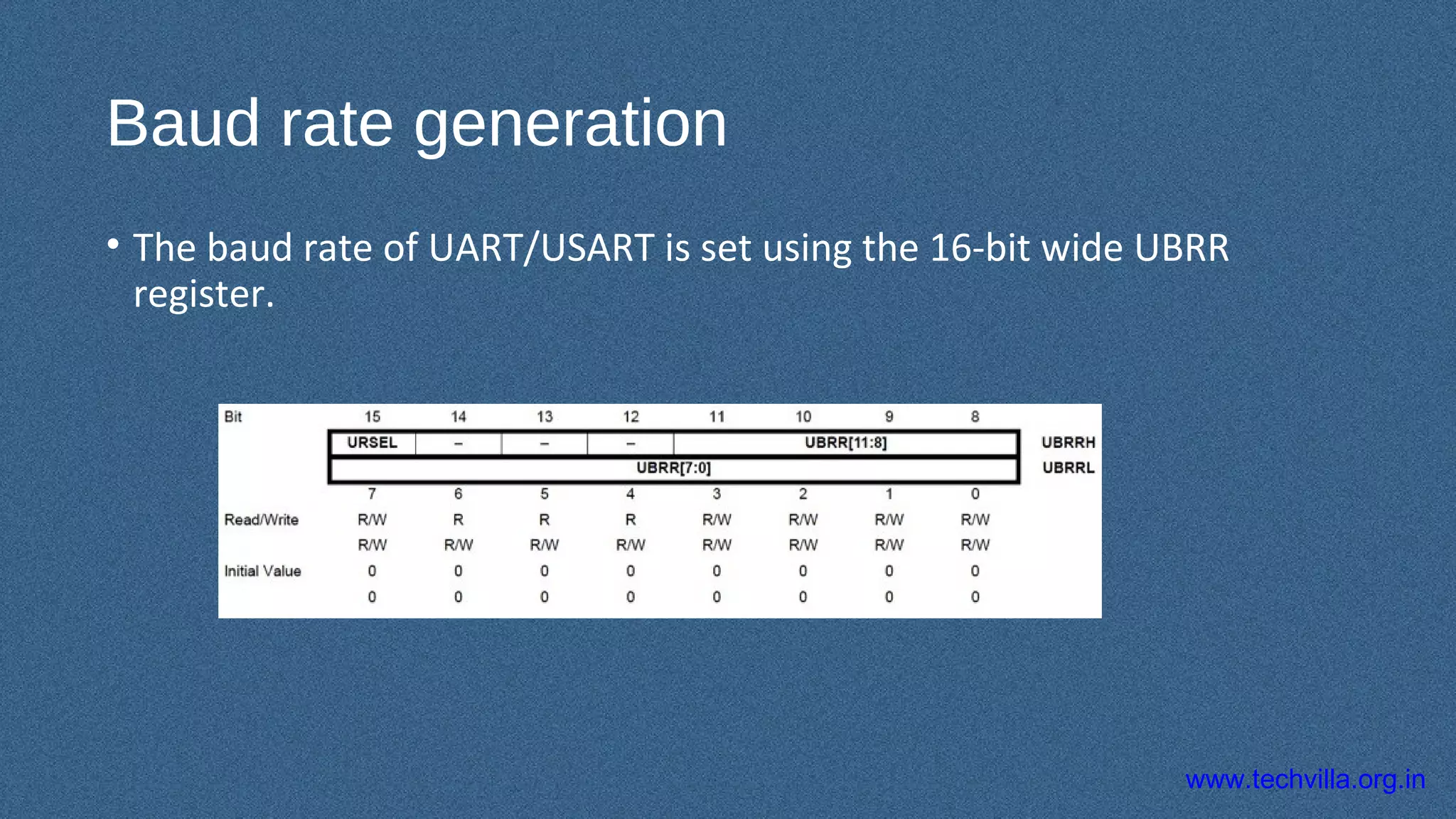
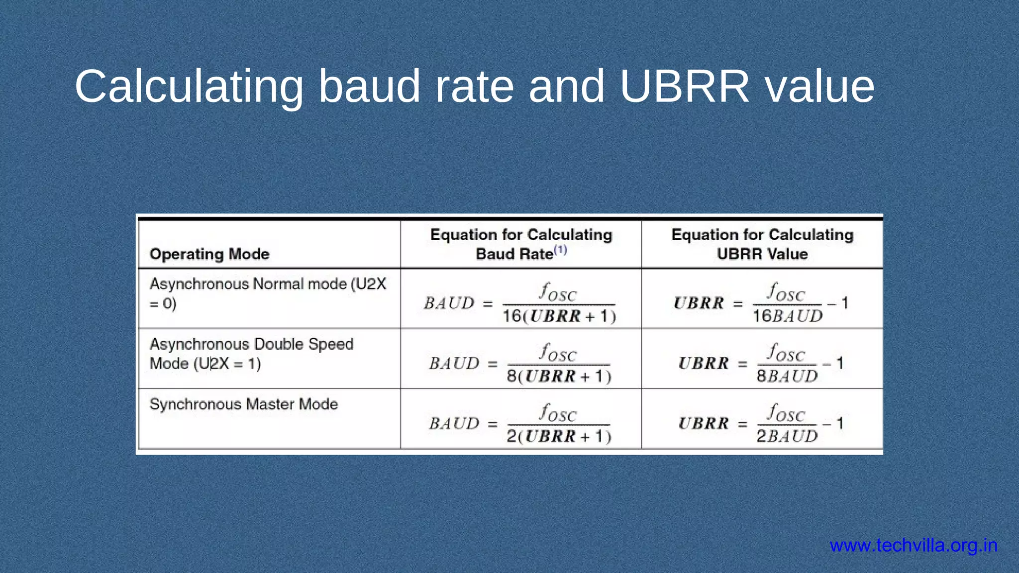
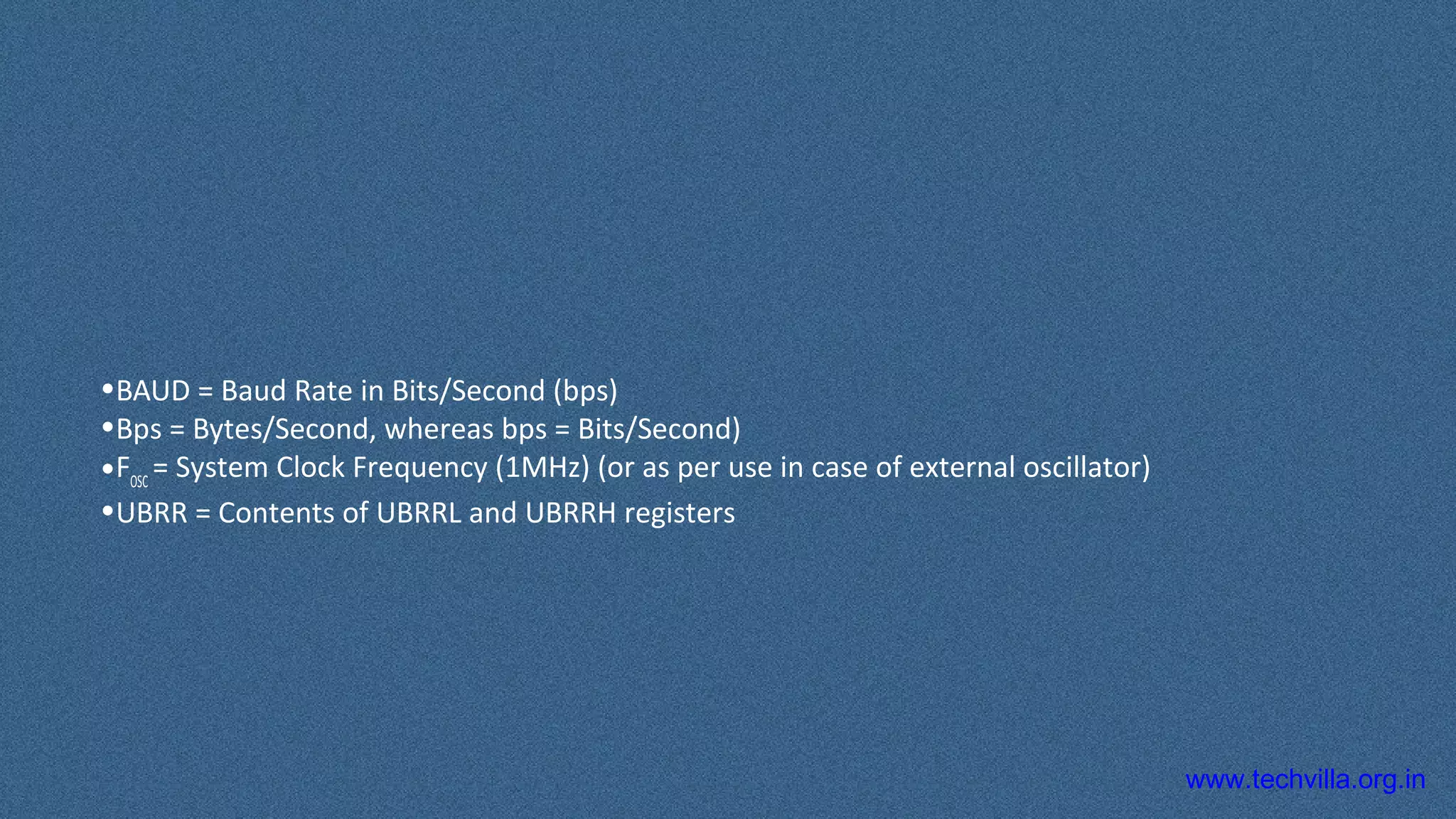
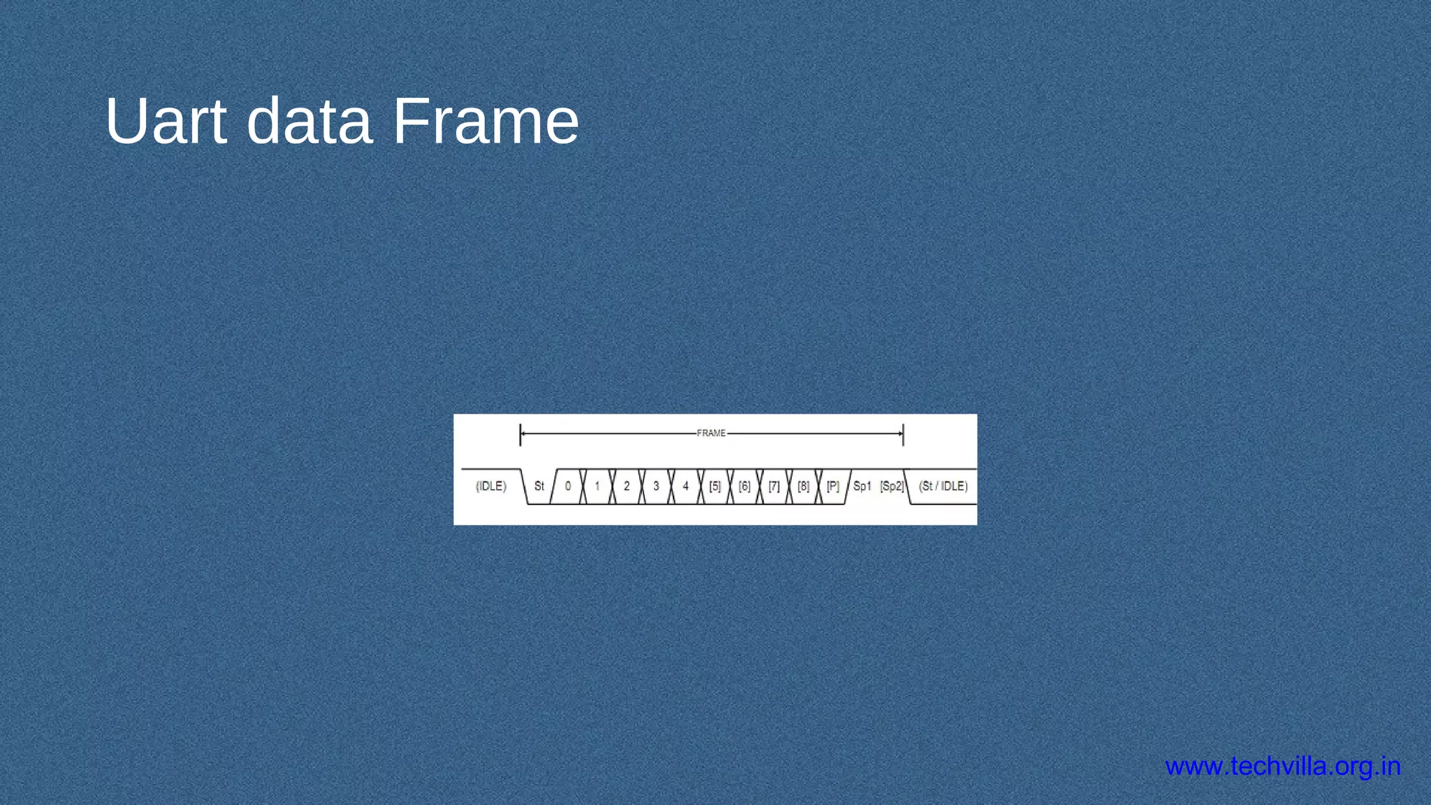
In telecommunication and computer science, serial communication is the process of sending data one bit at a time, sequentially, over a communication channel or computer bus. This is in contrast to parallel communication, where several bits are sent as a whole, on a link with several parallel channels.
Serial communication is used for all long-haul communication and most computer networks, where the cost of cable and synchronization difficulties make parallel communication impractical. Serial computer buses are becoming more common even at shorter distances, as improved signal integrity and transmission speeds in newer serial technologies have begun to outweigh the parallel bus's advantage of simplicity (no need for serializer and deserializer, or SerDes) and to outstrip its disadvantages (clock skew, interconnect density). The migration from PCI to PCI Express is an example.
4. www.techvilla.org.in
UART
• RS232 standard and
application, e.g.
4
3
RS232 port
(UART)
RS232 port
(UART)
RS232 standard
3 wires
+10 V=‘0’=SPACE
-10V=‘1’=MARK
Pin2
Pin3
pin5
Pin3
Pin2
pin5
5. www.techvilla.org.in
U Universal A Asynchronous R Receiver T Transmitter
UART for data communication
• Serial data transmission means sending data bits one by one using one
wire.
• Asynchronous transmission means a data (including one start bit , 8-
bit data, and stop bits) can be sent at any time.
5
4
6. www.techvilla.org.in
Universal asynchronous receiver transmitter : UART
• RS232 is a serial communication standard
• Since it is asynchronous, no external clock is needed, only 3 wires are
required for the simplest RS232 connection {GND, tx(transmit),
rx(receive)}
6
5
+10V=Logic 0=space
-10V= Logic 1=mark
Exercise: Sketch Bit Patterns for character A and B
Start 0 1 2 3 4 5 6 7 stop
Bit 0 to 7 (least sig. bit first )
time
8. www.techvilla.org.inCEG2400 Ch6. Serial Interface -- UART V4b
EXAMPLES
• Sending ASCII
• ‘5’=0x35=0011 0101b
8
7
Start bit=0
10101100(stop bit=1)
Least Sign. Bit first
What is this code ?
The whole ASCII serial character has 10 bits
(1 start+8 data + 1 stop bit)
Stop bit=1
Oscilloscope
Probe
T=bit period
=1/baud rate
9. www.techvilla.org.inCEG2400 Ch6. Serial Interface -- UART V4b
If the baud rate is 57600 bits per second
Define ‘bit period’ :the amount of time to transmit a logic 1 or 0. (bit period= 1/57600
seconds)
• Each bit lasts for (1/Baud rate) seconds
9
8
bit period =
1/baud rate =(1 / 57600) seconds=17.4 us
Exercise: What is the “bit period” in seconds if baud rate is 2400?
10. www.techvilla.org.in
Asynchronous Serial Communication
• With asynchronous communication, the transmitter and
receiver do not share a common clock
Transmitter Receiver+
1 byte-wide Data
Data
–
1 byte-wide Data
The Receiver
φ Extracts the data using its own
clock
φ Converts the serial data back
to the parallel form after
stripping off the start, stop and
parity bits
The Transmitter
φ Shifts the parallel data onto
the serial line using its own
clock
φ Also adds the start, stop and
parity check bits
Add: Start, Stop, Parity Bits Remove: Start, Stop, Parity Bits
11. www.techvilla.org.in
Asynchronous Serial Communication
• Start bit—indicates the beginning of the data word
• Stop bit—indicates the end of the data word
• Parity bit—added for error detection (optional)
• Data bits—the actual data to be transmitted
• Baud rate—the bit rate of the serial port
• Throughput—actual data transmitted per sec (total bits transmitted—overhead)
• Example: 115200 baud = 115200 bits/sec
• If using 8-bit data, 1 start, 1 stop, and no parity bits, the effective
throughput is: 115200 * 8 / 10 = 92160 bits/sec
12. www.techvilla.org.in
Asynchronous Serial Communication
• Asynchronous transmission is easy to implement but less
efficient as it requires an extra 2-3 control bits for every 8
data bits
• This method is usually used for low volume transmission
13. www.techvilla.org.in
Synchronous Serial Communication
• In the synchronous mode, the transmitter and receiver share a common clock
• The transmitter typically provides the clock as a separate signal in addition to the serial
data
Transmitter Receiver
Data
Clock
The Receiver
φ Extracts the data using
the clock provided by the
transmitter
φ Converts the serial data
back to the parallel form
The Transmitter
φ Shifts the data onto the serial
line using its own clock
φ Provides the clock as a
separate signal
φ No start, stop, or parity bits
added to data
1 byte-wide Data 1 byte-wide Data
16. www.techvilla.org.in
RS232
• For asynchronous communication.
• between two data serial links on a network Between a data─
communication equipment and data terminal equipment.
• RS232C a standard protocol used in IBM PC COM ports, keyboard,─
computer-mice and
• For the data serial link network in UART bit format
20. www.techvilla.org.in
How to set-up avr UART
• The first step is to set the baud rate in both, the master and the
slave. The baud rate has to be the same for both – master and slave.
• Set the number of data bits, which needs to be sent.
• Get the buffer ready! In case of transmission (from AVR to some other
device), load it up with the data to be sent, whereas in case of
reception, save the previous data so that the new received data can
be overwritten onto it.
• Then enable the transmitter/receiver according to the desired usage.
21. www.techvilla.org.in
• in UART, there is no master or slave since master is defined by the
MicroController, which is responsible for clock pulse generation.
• Master and Slave terms occur only in the case of USART.
• Master µC is the one which is responsible for Clock pulse generation
on the Bus.
23. www.techvilla.org.in
UBRR register
• he 16-bit UBRR register is comprised of two 8-bit registers – UBRRH
(high) and UBRRL (low).
• The USART Baud Rate Register (UBRR) and the down-counter
connected to it functions as a programmable prescaler or baud rate
generator.
• The down-counter, running at system clock (FOSC), is loaded with the
UBRR value each time the counter has counted down to zero or when
the UBRRL Register is written.
• A clock is generated each time the counter reaches zero.
25. www.techvilla.org.in
•BAUD = Baud Rate in Bits/Second (bps)
•Bps = Bytes/Second, whereas bps = Bits/Second)
•FOSC
= System Clock Frequency (1MHz) (or as per use in case of external oscillator)
•UBRR = Contents of UBRRL and UBRRH registers
27. www.techvilla.org.in
FRAME STRUCTURE
• USART communication uses special protocol to transmit data reliable.
It consists of several parts:
• 1 start bit;
• 5,6,7,8 or 9 data bits;
• no, even, or odd parity bit;
• 1 or 2 stop bits.
Editor's Notes
Asynchronous transmission is easy to implement but less efficient (i.e. slower) as it requires an extra 2-3 control bits for every 8 data bits.