Downloaded 492 times
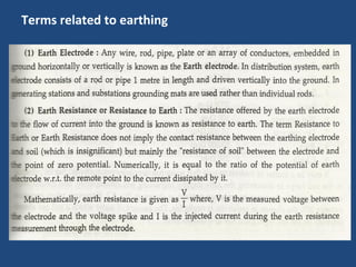
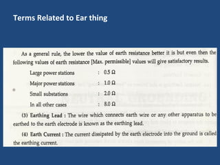
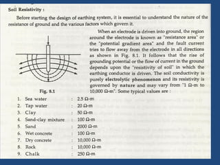
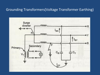
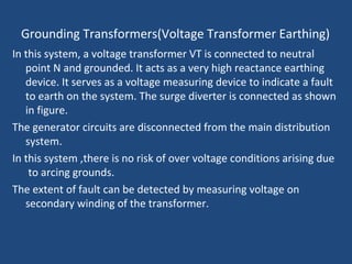
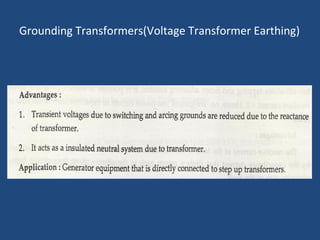
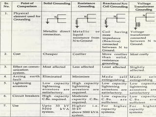
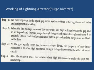
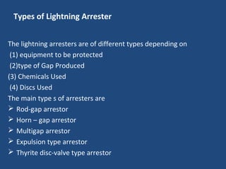
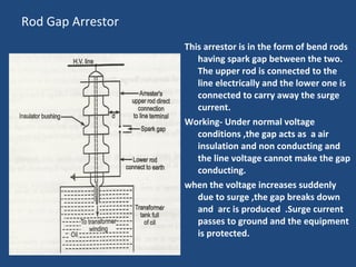

The document discusses various protection devices used in electrical installations, including air break and disconnect switches, grounding systems, and lightning protection measures. It details the importance of utilizing current limiting reactors to manage short circuit currents and outlines different grounding methods to enhance safety and reduce equipment damage. Additionally, the document covers the types and functions of lightning arresters, emphasizing their role in protecting transmission lines from lightning strikes and arcing phenomena.


