Downloaded 275 times

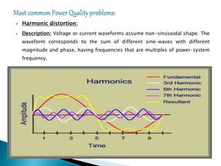
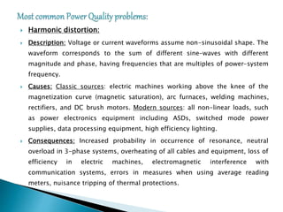


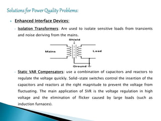
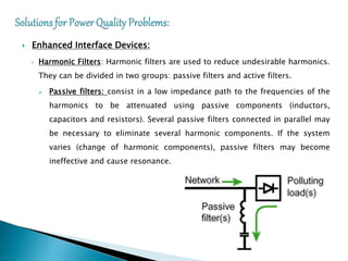
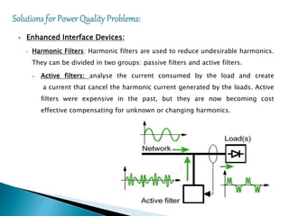
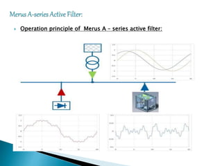
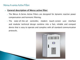

The document discusses various power quality problems such as harmonic distortion, voltage sags, swells, and interruptions. It then discusses solutions for power quality problems including maintaining grid adequacy, using distributed resources like distributed generation and energy storage, and implementing enhanced interface devices. The document also describes the operation of the Merus A-series Active Filter, which can be used to compensate for harmonics and reactive power in an electrical system.