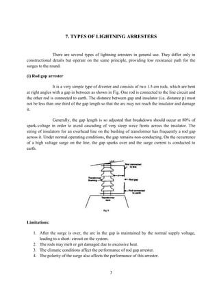
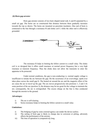
1. INTRODUCTION


                 Substation design involves more than installing apparatus, protective devices and
equipment. The significant momentary investment and required reliable continuous operation of
the facility requires detailed attention to preventing surges from entering the substation facility.
The effects of disturbances with limiting in a power system, which if allow to persist, may
damage plant and interrupt the supply of electrical energy. Lightning is one of the most serious
causes of over voltage. If the power equipment especially at outdoor substation is not protected
the over-voltage will cause burning of insulation. Thus it results into complete shutdown of the
power and the loss may run into cores of kyat. Electrical equipment can be damage due to over-
voltage such as switching surge over-voltage, Lightning surge over-voltage, transient recovery
voltage and power frequency temporary over-voltage in transmission line and receiving end of
substation. It is important to protect power equipment against them wherever possible; consistent
with sound economic .Lightning Arrester can protect the damages of electrical equipments. So,
Lightning Arrester needed to install in the terminal end of the transmission line, substation, high
voltage transformers and low voltage transformer. The analysis of electromagnetic transient is
depended on operating voltage, lengths of the lines and contactor configuration. So, it can be
chosen correctly the technical specifications of the apparatus of Lightning Arrester base on the
amounts of receiving over-voltage.


                                                 1
2. LIGHTNING ARRESTERS


                The earthing screen and ground wires fail to provide protection against traveling
waves. The lightning arrester provides protection against such surges. These are very much useful
for limiting surge voltages due to lightning strikes or equipment faults or other events, to prevent
damage to equipment and disruption of service

        Lightning arresters are installed on many different pieces of equipment such as power
poles and towers, power transformers, circuit breakers, bus structures, and steel superstructures in
substations. Lightning arrestors became a more crucial facet to our modern lifestyle in the 1980s
as the rapid proliferation of consumer technology resulted in the widespread use of electronic
devices, both at home and in the commercial sector, thus increasing the need for arrestors.


                                                 2
3. CONSTRUCTION OF LIGHTNING ARRESTER


                The fig (i) shows the basic form of a lightening arrester (surge diverter).it consists
of a spark gap in series with a non-linear resistor. One end of the diverter is connected to the
terminal of the equipment to be protected and other end is effectively grounded. The length of the
gap is so set that normal line voltage is not enough to cause an arc across the gap, but a
dangerously high voltage will breakdown the air insulation and form an arc. The property of the
non-linear resistance is that its resistance decreases as the voltage (or current) increases and vice
versa. This is clear from the volt-amp characteristics of the resistor shown in figure (ii)


                                                  3
4. WORKING PRINCIPLE OF LIGHTNING ARRESTER


              The basic principle behind this life saving system is the "corona discharge". It is
nothing but the discharge (or) leakage of electric charges from the sharp points of a charged
conductor.

The action of lightning arrester is as under

   i)      Under normal operation, the lightning arrester is off ie no current to earth or the gap is
           non-conducting.

   ii)     On the occurrence of overvoltage, the air insulation across the gap breaks down and
           the arc is formed, providing a low resistance path for the surge to the ground. In this
           way, the excess charge on the line due to the surge is harmlessly conducted through
           the arrester to the ground instead of being sent back over the line.

   iii)    It is worthwhile to mention the function of non-linear resistor in the operation of
           arrester. As the gap sparks over due to over voltage, the arc would be a short-circuit
           on the power system and may cause power-follow current in the arrester. Since the
           characteristic of the resistor is to offer low resistance to high voltage (or current), it
           gives the effect of short-circuit. After the surge is over, the resistor offers high
           resistance to make the gap non-conducting.

    Two things must be taken care in the design of a lightning arrester. Firstly, when the surge is
over, the air in gap should cease the arc does not go out, the current would continue to flow
through the resistor and both resistor and gap may be destroyed. Secondly, IR gap (where I is the
surge current) across the arrester when carrying surge current should not exceed the breakdown
strength of the insulation of the equipment to be protected.


                                                 4
5. IDEAL CHARACTERISTICS OF LIGHTNING ARRESTERS


                A diverter is connected in parallel or shunt with the equipment to be protected at
the substation between the line and ground. Ideally, it should
    i)      enter into conduction at some voltage above arrester rating
    ii)     hold that voltage with little change for the duration of the overvoltage surge, and
    iii)    substantially cease conduction at very nearly the same voltage at which the conduction
            started

What exactly surge arresters do?

1. Surge Arresters does not absorb the lightning.
2. Surge Arresters does not stop the lightning.
3. Surge Arresters divert the lightning to ground.
4. Surge Arresters clamp (limit) the voltage produced by lightning.
5. Surge Arresters equipment electrically in parallel with it.


                                                5
6. INSTALLATION AND MAINTENANCE


Installation of lightening arresters:

        The arrester should be connected to ground to a low resistance for effective discharge of the surge
current.
        The arrester should be mounted close to the equipment to be protected & connected with shortest
possible lead on both the line & ground side to reduce the inductive effects of the leads while discharging
large surge current.


Maintenance of lightning arresters:

       Cleaning the outside of the arrester housing.
       The line should be de-energized before handling the arrester.
       The earth connection should be checked periodically.
       To record the readings of the surge counter.
       The line lead is securely fastened to the line conductor and arrester
       The ground lead is securely fastened to the arrester terminal and ground.


                                                 6
7. TYPES OF LIGHTNING ARRESTERS


                There are several types of lightning arresters in general use. They differ only in
constructional details but operate on the same principle, providing low resistance path for the
surges to the round.

(i) Rod gap arrester

                It is a very simple type of diverter and consists of two 1.5 cm rods, which are bent
at right angles with a gap in between as shown in Fig. One rod is connected to the line circuit and
the other rod is connected to earth. The distance between gap and insulator (i.e. distance p) must
not be less than one third of the gap length so that the arc may not reach the insulator and damage
it.

                Generally, the gap length is so adjusted that breakdown should occur at 80% of
spark-voltage in order to avoid cascading of very steep wave fronts across the insulator. The
string of insulators for an overhead line on the bushing of transformer has frequently a rod gap
across it. Under normal operating conditions, the gap remains non-conducting. On the occurrence
of a high voltage surge on the line, the gap sparks over and the surge current is conducted to
earth.


Limitations:

   1. After the surge is over, the arc in the gap is maintained by the normal supply voltage,
      leading to a short- circuit on the system.
   2. The rods may melt or get damaged due to excessive heat.
   3. The climatic conditions affect the performance of rod gap arrester.
   4. The polarity of the surge also affects the performance of this arrester.


                                                 7
(ii) Horn gap arrester

              Horn gap arrester consists of two horn shaped metal rods A and B separated by a
small air gap. The horns are so constructed that distance between them gradually increases
towards the top as shown. The horns are mounted on porcelain insulators. One end of horn is
connected to the line through a resistance R and choke coil L while the other end is effectively
grounded.


               The resistance R helps in limiting the follow current to a small value. The choke
coil is so designed that it offers small reactance at normal power frequency but a very high
reactance at transient frequency. Thus the choke does not allow the transients to enter the
apparatus to be protected.

                Under normal conditions, the gap is non-conducting i.e. normal supply voltage is
insufficient to initiate the arc between the gap. On the occurrence of an overvoltage, spark-over
takes place across the small gap G. The heated air around the arc and the magnetic effect of the
arc cause the arc to travel up the gap. The arc moves progressively into positions 1, 2 and 3.At
some position of the arc (position 3), the distance may be too great for the voltage to maintain the
arc; consequently, the arc is extinguished. The excess charge on the line is thus conducted
through the arrester to the ground.

Advantages:

   i)      The arc is self-clearing.
   ii)     Series resistance helps in limiting the follow current to a small value.

Limitations:

   i)      The bridging of gap by some external agency can render the device useless.
   ii)     The setting of horn gap is likely to change due to corrosion or pitting, adversely
           affects the performance of the arrester.
   iii)    The time of operation is comparatively long.

                                                 8
(iii) Multi gap arrester

                It consists of a series of metallic (generally alloy of zinc) cylinders insulated from
one another and separated by small intervals of air gaps. The first cylinder (i.e. A) in the series is
connected to the line and the others to the ground through a series resistance. The series
resistance limits the power arc. By the inclusion of series resistance, the degree of protection
against traveling waves is reduced.

               In order to overcome this difficulty, some of the gaps (B to C in Fig) are shunted
by resistance. Under normal conditions, the point B is at earth potential and the normal supply
voltage is unable to break down the series gaps. On the occurrence of an over voltage, the
breakdown of series gaps A to B occurs. The heavy current after breakdown will choose the
straight – through path to earth via the shunted gaps B and C, instead of the alternative path
through the shunt resistance.


                When the surge is over, the arcs B to C go out and any power current following
the surge is limited by the two resistances (shunt resistance and series resistance) which are now
in series. The current is too small to maintain the arcs in the gaps A to B and normal conditions
are restored. Such arresters can be employed where system voltage does not exceed 33kV.

(iv) Expulsion type arrester

                This type of arrester is also called ’protector tube’ and is commonly used on
system operating at voltages up to 33kV. Fig i) shows the essential parts of an expulsion type
lightning arrester.

               It essentially consists of a rod gap AA’ in series with a second gap enclosed within
the fiber tube. The gap in the fiber tube is formed by two electrodes. The upper electrode is
connected to rod gap and the lower electrode to the earth. One expulsion arrester is placed under
each line conductor. Fig ii) shows the installation of expulsion arrester on an overhead line.


                                                  9
On the occurrence of an over voltage on the line, the series gap AA’ is spanned
and an arc is stuck between the electrodes in the tube. The heat of the arc vaporizes some of the
fiber of tube walls resulting in the production of neutral gas. In an extremely short time, the gas
builds up high pressure and is expelled through the lower electrode, which is hollow. As the gas
leaves the tube violently, it carries away ionized air around the arc. This de-ionizing effect is
generally so strong that the arc goes out at a current zero and will not be re-established.

Advantages:


   1. They are not very expensive.
   2. They are improved form of rod gap arresters as they block the flow of power frequency
      follow currents
   3. They can be easily installed.

Limitations

   1. An expulsion type arrester can perform only limited number of operations as during each
      operation some of the fiber material is used up.
   2. This type of arrester cannot be mounted in enclosed equipment due to the discharge of
      gases during operation.
   3. Due to the poor volt/amp characteristic of the arrester, it is not suitable for protection of
      expensive equipment


                                                10
(v) Valve type arrester


              Valve type arresters incorporate non linear resistors and are extensively used on
systems, operating at high voltages. Fig i) shows the various parts of a valve type arrester.
       It consists of two assemblies
   i) series spark gaps and
   ii) Non-linear resistor discs (made of material such as thyrite or metrosil) in series. The non-
       linear elements are connected in series with the spark gaps. Both the assemblies are
       accommodated in tight porcelain container.

               i) The spark gap is a multiple assembly consisting of a number of identical spark
gaps in series. Each gap consists of two electrodes with fixed gap spacing. The voltage
distribution across the gaps is linearised by means of additional resistance elements called
grading resistors across the gap. The spacing of the series gaps is such that it will withstand the
normal circuit voltage. However an over voltage will cause the gap to breakdown, causing the
surge current to ground via the non-linear resistors.

                ii) The non-linear resistor discs are made of an inorganic compound such as thyrite
or metrosil. These discs are connected in series. The non-linear resistors have the property of
offering a high resistance to current flow when normal system voltage is applied, but a low
resistance to the flow of high surge currents. In other words, the resistance of these non-linear
elements decreases with the increase in current through them and vice-versa.


                                                11
Under normal conditions, the normal system voltage is insufficient to cause the
breakdown of air gap assembly. On the occurrence of an over voltage, the breakdown of the series spark
gap takes place and the surge current is conducted to earth via the non-linear resistors.

               Since the magnitude of surge current is very large, the non-linear elements will
offer a very low resistance to the passage of surge. The result is that the surge will rapidly go to
earth instead of being sent back over the line. When the surge is over, the non-linear resistors
assume high resistance to stop the flow of current.

Advantages:

   i)      They provide very effective protection (especially for transformers and cables) against
           surges.
   ii)     They operate very rapidly taking less than a second.
   iii)    The impulse ratio is practically unity.(impulse ratio = breakdown voltage under surge
           conditions / breakdown voltage under low frequency conditions)

Limitations:

   i)      They may fail to check the surges of very steep wave front from reaching the terminal
           apparatus. This calls for additional steps to check steep-fronted waves.
   ii)     Their performance is adversely affected by the entry of moisture into the enclosure.
           This necessitates effective sealing of the enclosure at all times.

vi) Metal oxide varistor:
              At the heart of all arresters is Metal Oxide Varistor (MOV). The MOV disk is a
semiconductor that is sensitive to voltage. At normal voltage, the MOV disk is an insulator and
will not conduct current. But at higher (extreme) voltage caused by lightning or any surges, it
becomes a conductor.
                The usual construction of a typical surge arrester consists of disks of zinc oxide
material sized in cross-sectional area to provide desired energy discharge capability, and in axial
length proportional to the voltage capability. The disks are then placed in porcelain enclosures to
provide physical support and heat removal, and sealed for isolation from contamination in the
electrical environment.

                When a surge of electricity such as a lightning strike hits an electrical system, it
naturally seeks a way to equalize and dissipate itself as quickly as possible, taking the path of
least resistance. A resistor provides the most efficient route for the surge by diverting the
electricity away from the equipment's insulation and channeling it into the ground via grounding
rods. In order to do this, the resistor uses a metal oxide varistor (MOV), which is a component
with a diode-like nonlinear current-voltage characteristic that is triggered when voltages reach
sensitive levels. Specifically, the varistor's symmetrical, sharp breakdown characteristics allow it
to achieve a high level of transient electrical suppression performance. The word "varistor" is a
portmanteau that combines variable and resistor


                                                 12
Advantages:

1. Residual depression.
2. Fast response time, 25ns or so.
3. Free wheeling.

Limitations:

Leakage current, parasitic capacitance larger, is not conducive to the protection of high-frequency
electronic circuits.


                                                13
Conclusion
                 All electrical equipment in an electrical system needs to be protected from voltage surges.
The rating of the arrester, the class of arrester and the location of the arrester all play a part in the
surge protection. Modern metal oxide arresters provide markedly superior protective characteristics and
energy absorption capability, compared to previous generation arresters. The application and selection of
metal oxide arresters requires a thorough review of the power system, including voltage, system stresses,
switching surges, grounding method and MCOV.


                                                     14
References


1. A text book on Principles of power system by v.k.mehta and rohit Mehta;4th edition.

2. www.seminarpaper.com.

3. www.arresterworks.com.
4. www.scribd.com.


                                               15
xvi

Shruthi

  • 1.
    1. INTRODUCTION Substation design involves more than installing apparatus, protective devices and equipment. The significant momentary investment and required reliable continuous operation of the facility requires detailed attention to preventing surges from entering the substation facility. The effects of disturbances with limiting in a power system, which if allow to persist, may damage plant and interrupt the supply of electrical energy. Lightning is one of the most serious causes of over voltage. If the power equipment especially at outdoor substation is not protected the over-voltage will cause burning of insulation. Thus it results into complete shutdown of the power and the loss may run into cores of kyat. Electrical equipment can be damage due to over- voltage such as switching surge over-voltage, Lightning surge over-voltage, transient recovery voltage and power frequency temporary over-voltage in transmission line and receiving end of substation. It is important to protect power equipment against them wherever possible; consistent with sound economic .Lightning Arrester can protect the damages of electrical equipments. So, Lightning Arrester needed to install in the terminal end of the transmission line, substation, high voltage transformers and low voltage transformer. The analysis of electromagnetic transient is depended on operating voltage, lengths of the lines and contactor configuration. So, it can be chosen correctly the technical specifications of the apparatus of Lightning Arrester base on the amounts of receiving over-voltage. 1
  • 2.
    2. LIGHTNING ARRESTERS The earthing screen and ground wires fail to provide protection against traveling waves. The lightning arrester provides protection against such surges. These are very much useful for limiting surge voltages due to lightning strikes or equipment faults or other events, to prevent damage to equipment and disruption of service Lightning arresters are installed on many different pieces of equipment such as power poles and towers, power transformers, circuit breakers, bus structures, and steel superstructures in substations. Lightning arrestors became a more crucial facet to our modern lifestyle in the 1980s as the rapid proliferation of consumer technology resulted in the widespread use of electronic devices, both at home and in the commercial sector, thus increasing the need for arrestors. 2
  • 3.
    3. CONSTRUCTION OFLIGHTNING ARRESTER The fig (i) shows the basic form of a lightening arrester (surge diverter).it consists of a spark gap in series with a non-linear resistor. One end of the diverter is connected to the terminal of the equipment to be protected and other end is effectively grounded. The length of the gap is so set that normal line voltage is not enough to cause an arc across the gap, but a dangerously high voltage will breakdown the air insulation and form an arc. The property of the non-linear resistance is that its resistance decreases as the voltage (or current) increases and vice versa. This is clear from the volt-amp characteristics of the resistor shown in figure (ii) 3
  • 4.
    4. WORKING PRINCIPLEOF LIGHTNING ARRESTER The basic principle behind this life saving system is the "corona discharge". It is nothing but the discharge (or) leakage of electric charges from the sharp points of a charged conductor. The action of lightning arrester is as under i) Under normal operation, the lightning arrester is off ie no current to earth or the gap is non-conducting. ii) On the occurrence of overvoltage, the air insulation across the gap breaks down and the arc is formed, providing a low resistance path for the surge to the ground. In this way, the excess charge on the line due to the surge is harmlessly conducted through the arrester to the ground instead of being sent back over the line. iii) It is worthwhile to mention the function of non-linear resistor in the operation of arrester. As the gap sparks over due to over voltage, the arc would be a short-circuit on the power system and may cause power-follow current in the arrester. Since the characteristic of the resistor is to offer low resistance to high voltage (or current), it gives the effect of short-circuit. After the surge is over, the resistor offers high resistance to make the gap non-conducting. Two things must be taken care in the design of a lightning arrester. Firstly, when the surge is over, the air in gap should cease the arc does not go out, the current would continue to flow through the resistor and both resistor and gap may be destroyed. Secondly, IR gap (where I is the surge current) across the arrester when carrying surge current should not exceed the breakdown strength of the insulation of the equipment to be protected. 4
  • 5.
    5. IDEAL CHARACTERISTICSOF LIGHTNING ARRESTERS A diverter is connected in parallel or shunt with the equipment to be protected at the substation between the line and ground. Ideally, it should i) enter into conduction at some voltage above arrester rating ii) hold that voltage with little change for the duration of the overvoltage surge, and iii) substantially cease conduction at very nearly the same voltage at which the conduction started What exactly surge arresters do? 1. Surge Arresters does not absorb the lightning. 2. Surge Arresters does not stop the lightning. 3. Surge Arresters divert the lightning to ground. 4. Surge Arresters clamp (limit) the voltage produced by lightning. 5. Surge Arresters equipment electrically in parallel with it. 5
  • 6.
    6. INSTALLATION ANDMAINTENANCE Installation of lightening arresters: The arrester should be connected to ground to a low resistance for effective discharge of the surge current. The arrester should be mounted close to the equipment to be protected & connected with shortest possible lead on both the line & ground side to reduce the inductive effects of the leads while discharging large surge current. Maintenance of lightning arresters: Cleaning the outside of the arrester housing. The line should be de-energized before handling the arrester. The earth connection should be checked periodically. To record the readings of the surge counter. The line lead is securely fastened to the line conductor and arrester The ground lead is securely fastened to the arrester terminal and ground. 6
  • 7.
    7. TYPES OFLIGHTNING ARRESTERS There are several types of lightning arresters in general use. They differ only in constructional details but operate on the same principle, providing low resistance path for the surges to the round. (i) Rod gap arrester It is a very simple type of diverter and consists of two 1.5 cm rods, which are bent at right angles with a gap in between as shown in Fig. One rod is connected to the line circuit and the other rod is connected to earth. The distance between gap and insulator (i.e. distance p) must not be less than one third of the gap length so that the arc may not reach the insulator and damage it. Generally, the gap length is so adjusted that breakdown should occur at 80% of spark-voltage in order to avoid cascading of very steep wave fronts across the insulator. The string of insulators for an overhead line on the bushing of transformer has frequently a rod gap across it. Under normal operating conditions, the gap remains non-conducting. On the occurrence of a high voltage surge on the line, the gap sparks over and the surge current is conducted to earth. Limitations: 1. After the surge is over, the arc in the gap is maintained by the normal supply voltage, leading to a short- circuit on the system. 2. The rods may melt or get damaged due to excessive heat. 3. The climatic conditions affect the performance of rod gap arrester. 4. The polarity of the surge also affects the performance of this arrester. 7
  • 8.
    (ii) Horn gaparrester Horn gap arrester consists of two horn shaped metal rods A and B separated by a small air gap. The horns are so constructed that distance between them gradually increases towards the top as shown. The horns are mounted on porcelain insulators. One end of horn is connected to the line through a resistance R and choke coil L while the other end is effectively grounded. The resistance R helps in limiting the follow current to a small value. The choke coil is so designed that it offers small reactance at normal power frequency but a very high reactance at transient frequency. Thus the choke does not allow the transients to enter the apparatus to be protected. Under normal conditions, the gap is non-conducting i.e. normal supply voltage is insufficient to initiate the arc between the gap. On the occurrence of an overvoltage, spark-over takes place across the small gap G. The heated air around the arc and the magnetic effect of the arc cause the arc to travel up the gap. The arc moves progressively into positions 1, 2 and 3.At some position of the arc (position 3), the distance may be too great for the voltage to maintain the arc; consequently, the arc is extinguished. The excess charge on the line is thus conducted through the arrester to the ground. Advantages: i) The arc is self-clearing. ii) Series resistance helps in limiting the follow current to a small value. Limitations: i) The bridging of gap by some external agency can render the device useless. ii) The setting of horn gap is likely to change due to corrosion or pitting, adversely affects the performance of the arrester. iii) The time of operation is comparatively long. 8
  • 9.
    (iii) Multi gaparrester It consists of a series of metallic (generally alloy of zinc) cylinders insulated from one another and separated by small intervals of air gaps. The first cylinder (i.e. A) in the series is connected to the line and the others to the ground through a series resistance. The series resistance limits the power arc. By the inclusion of series resistance, the degree of protection against traveling waves is reduced. In order to overcome this difficulty, some of the gaps (B to C in Fig) are shunted by resistance. Under normal conditions, the point B is at earth potential and the normal supply voltage is unable to break down the series gaps. On the occurrence of an over voltage, the breakdown of series gaps A to B occurs. The heavy current after breakdown will choose the straight – through path to earth via the shunted gaps B and C, instead of the alternative path through the shunt resistance. When the surge is over, the arcs B to C go out and any power current following the surge is limited by the two resistances (shunt resistance and series resistance) which are now in series. The current is too small to maintain the arcs in the gaps A to B and normal conditions are restored. Such arresters can be employed where system voltage does not exceed 33kV. (iv) Expulsion type arrester This type of arrester is also called ’protector tube’ and is commonly used on system operating at voltages up to 33kV. Fig i) shows the essential parts of an expulsion type lightning arrester. It essentially consists of a rod gap AA’ in series with a second gap enclosed within the fiber tube. The gap in the fiber tube is formed by two electrodes. The upper electrode is connected to rod gap and the lower electrode to the earth. One expulsion arrester is placed under each line conductor. Fig ii) shows the installation of expulsion arrester on an overhead line. 9
  • 10.
    On the occurrenceof an over voltage on the line, the series gap AA’ is spanned and an arc is stuck between the electrodes in the tube. The heat of the arc vaporizes some of the fiber of tube walls resulting in the production of neutral gas. In an extremely short time, the gas builds up high pressure and is expelled through the lower electrode, which is hollow. As the gas leaves the tube violently, it carries away ionized air around the arc. This de-ionizing effect is generally so strong that the arc goes out at a current zero and will not be re-established. Advantages: 1. They are not very expensive. 2. They are improved form of rod gap arresters as they block the flow of power frequency follow currents 3. They can be easily installed. Limitations 1. An expulsion type arrester can perform only limited number of operations as during each operation some of the fiber material is used up. 2. This type of arrester cannot be mounted in enclosed equipment due to the discharge of gases during operation. 3. Due to the poor volt/amp characteristic of the arrester, it is not suitable for protection of expensive equipment 10
  • 11.
    (v) Valve typearrester Valve type arresters incorporate non linear resistors and are extensively used on systems, operating at high voltages. Fig i) shows the various parts of a valve type arrester. It consists of two assemblies i) series spark gaps and ii) Non-linear resistor discs (made of material such as thyrite or metrosil) in series. The non- linear elements are connected in series with the spark gaps. Both the assemblies are accommodated in tight porcelain container. i) The spark gap is a multiple assembly consisting of a number of identical spark gaps in series. Each gap consists of two electrodes with fixed gap spacing. The voltage distribution across the gaps is linearised by means of additional resistance elements called grading resistors across the gap. The spacing of the series gaps is such that it will withstand the normal circuit voltage. However an over voltage will cause the gap to breakdown, causing the surge current to ground via the non-linear resistors. ii) The non-linear resistor discs are made of an inorganic compound such as thyrite or metrosil. These discs are connected in series. The non-linear resistors have the property of offering a high resistance to current flow when normal system voltage is applied, but a low resistance to the flow of high surge currents. In other words, the resistance of these non-linear elements decreases with the increase in current through them and vice-versa. 11
  • 12.
    Under normal conditions,the normal system voltage is insufficient to cause the breakdown of air gap assembly. On the occurrence of an over voltage, the breakdown of the series spark gap takes place and the surge current is conducted to earth via the non-linear resistors. Since the magnitude of surge current is very large, the non-linear elements will offer a very low resistance to the passage of surge. The result is that the surge will rapidly go to earth instead of being sent back over the line. When the surge is over, the non-linear resistors assume high resistance to stop the flow of current. Advantages: i) They provide very effective protection (especially for transformers and cables) against surges. ii) They operate very rapidly taking less than a second. iii) The impulse ratio is practically unity.(impulse ratio = breakdown voltage under surge conditions / breakdown voltage under low frequency conditions) Limitations: i) They may fail to check the surges of very steep wave front from reaching the terminal apparatus. This calls for additional steps to check steep-fronted waves. ii) Their performance is adversely affected by the entry of moisture into the enclosure. This necessitates effective sealing of the enclosure at all times. vi) Metal oxide varistor: At the heart of all arresters is Metal Oxide Varistor (MOV). The MOV disk is a semiconductor that is sensitive to voltage. At normal voltage, the MOV disk is an insulator and will not conduct current. But at higher (extreme) voltage caused by lightning or any surges, it becomes a conductor. The usual construction of a typical surge arrester consists of disks of zinc oxide material sized in cross-sectional area to provide desired energy discharge capability, and in axial length proportional to the voltage capability. The disks are then placed in porcelain enclosures to provide physical support and heat removal, and sealed for isolation from contamination in the electrical environment. When a surge of electricity such as a lightning strike hits an electrical system, it naturally seeks a way to equalize and dissipate itself as quickly as possible, taking the path of least resistance. A resistor provides the most efficient route for the surge by diverting the electricity away from the equipment's insulation and channeling it into the ground via grounding rods. In order to do this, the resistor uses a metal oxide varistor (MOV), which is a component with a diode-like nonlinear current-voltage characteristic that is triggered when voltages reach sensitive levels. Specifically, the varistor's symmetrical, sharp breakdown characteristics allow it to achieve a high level of transient electrical suppression performance. The word "varistor" is a portmanteau that combines variable and resistor 12
  • 13.
    Advantages: 1. Residual depression. 2.Fast response time, 25ns or so. 3. Free wheeling. Limitations: Leakage current, parasitic capacitance larger, is not conducive to the protection of high-frequency electronic circuits. 13
  • 14.
    Conclusion All electrical equipment in an electrical system needs to be protected from voltage surges. The rating of the arrester, the class of arrester and the location of the arrester all play a part in the surge protection. Modern metal oxide arresters provide markedly superior protective characteristics and energy absorption capability, compared to previous generation arresters. The application and selection of metal oxide arresters requires a thorough review of the power system, including voltage, system stresses, switching surges, grounding method and MCOV. 14
  • 15.
    References 1. A textbook on Principles of power system by v.k.mehta and rohit Mehta;4th edition. 2. www.seminarpaper.com. 3. www.arresterworks.com. 4. www.scribd.com. 15
  • 16.