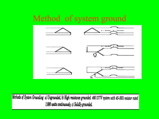
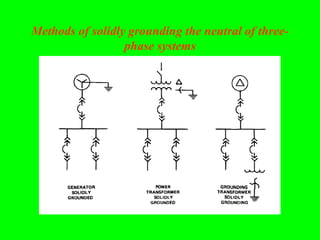
The document discusses different types of grounding systems used in high voltage systems, including: equipment grounds which connect metal parts to earth to protect from electric shock; system grounds which connect one point of an electrical circuit to earth to protect equipment and aid fault detection; and solidly grounded systems where the neutral is directly connected to ground without impedance. It notes factors like voltage level, equipment type, and safety that influence grounding method selection.
What is Grounding?
• Importance of Grounding
• Types of Grounding
• Applications of Grounding in power system
• Instruments employed in Grounding
• Grounding procedure & calculations
• Hazards due to lack of Grounding
• Good Grounding practice
• IEEE rules regarding Grounding
• Conclusion
What is Grounding?
• Importance of Grounding
• Types of Grounding
• Applications of Grounding in power system
• Instruments employed in Grounding
• Grounding procedure & calculations
• Hazards due to lack of Grounding
• Good Grounding practice
• IEEE rules regarding Grounding
• Conclusion
Grounding or earthing offers two principal advantages. First, it provides protection to the power system. Secondly, earthing of electrical equipment ensures the safety of the persons handling the equipment.
A switchgear or electrical switchgear is a generic term which includes all the switching devices associated with mainly power system protection. It also includes all devices associated with control, metering and regulating of electrical power system. Assembly of such devices in a logical manner forms a switchgear. This is the very basic definition of switchgear.
⋗To get more with details
https://www.youtube.com/channel/UC2SvKI7eepP241VLoui1D5A
Tutorial on Distance and Over Current ProtectionSARAVANAN A
Contents
• Protection Philosophy of ERPC
• Computation of Distance Relay Setting
• System Study to Understand Distance Relay
Behaviour
• DOC and DEF for EHV system
In this presentation talk about:
Able to describe Substation.
Importance of substation.
Factors governing the selection of side.
Classification of Sub-Station.
Elements of a substation.
Operation of substation.
Hazards & safety.
Recent substation accident Bangladesh.
Grounding:
A conducting connection, whether intentional or accidental, bywhich an electric circuit or equipment is connected to the earth, or to someconducting body of relatively large extent that serves in place of the earth.
Grounded system:
A system of conductors in which at least one conductor or point (usually the middle wire or neutral point of transformer or generator windings) is intentionally grounded, either solidly or through an impedance.
Grounded solidly:
Connected directly through an adequate ground connection in which no impedance has been intentionally inserted.
Grounded effectively:
Grounded through a sufficiently low impedance such that for all system conditions the ratio of zero sequence reactance to positive sequence reactance (X0/X1) is positive and less than 3, and the ratio of zero sequence resistance to positive sequence reactance (R0/X1) is positive and less than 1.
This presentation, given by Georgia Power, discusses the importance of grounding and bonding. Real life examples are given and how they were handled as well as safety measures.
PROTECTION AGAINST OVER VOLTAGE AND GROUNDING Part 2Dr. Rohit Babu
Grounded and ungrounded neutral systems
Effects of ungrounded neutral on system performance
Methods of neutral grounding
Solid
Resistance
Reactance
Arcing grounds and grounding Practices
PROTECTION AGAINST OVER VOLTAGE AND GROUNDINGDr. Rohit Babu
Generation of overvoltages in power systems
Protection against lightning overvoltages
Valve type and zinc oxide lightning arresters
Insulation coordination
BIL
Impulse ratio
Standard impulse test wave
Volt-time characteristics
Grounded and ungrounded neutral systems
Effects of ungrounded neutral on system performance
Methods of neutral grounding
Solid
Resistance
Reactance
Arcing grounds and grounding Practices
SYSTEM NEUTRAL EARTHING
-DEFINITION OF SYSTEM EARTHING
-Comparative Performance For Various Conditions Using Different Earthing Methods
-EQUIPMENT SIZING
- APPENDIX FOR TYPICAL EARTHING TRANSFORMER SIZING
- APPENDIX GIVING GUIDELINE FOR SIZING OF COMMON BUS CONNECTED MEDIUM RESISTANCE EARTHING
Macroeconomics- Movie Location
This will be used as part of your Personal Professional Portfolio once graded.
Objective:
Prepare a presentation or a paper using research, basic comparative analysis, data organization and application of economic information. You will make an informed assessment of an economic climate outside of the United States to accomplish an entertainment industry objective.
Biological screening of herbal drugs: Introduction and Need for
Phyto-Pharmacological Screening, New Strategies for evaluating
Natural Products, In vitro evaluation techniques for Antioxidants, Antimicrobial and Anticancer drugs. In vivo evaluation techniques
for Anti-inflammatory, Antiulcer, Anticancer, Wound healing, Antidiabetic, Hepatoprotective, Cardio protective, Diuretics and
Antifertility, Toxicity studies as per OECD guidelines
June 3, 2024 Anti-Semitism Letter Sent to MIT President Kornbluth and MIT Cor...Levi Shapiro
Letter from the Congress of the United States regarding Anti-Semitism sent June 3rd to MIT President Sally Kornbluth, MIT Corp Chair, Mark Gorenberg
Dear Dr. Kornbluth and Mr. Gorenberg,
The US House of Representatives is deeply concerned by ongoing and pervasive acts of antisemitic
harassment and intimidation at the Massachusetts Institute of Technology (MIT). Failing to act decisively to ensure a safe learning environment for all students would be a grave dereliction of your responsibilities as President of MIT and Chair of the MIT Corporation.
This Congress will not stand idly by and allow an environment hostile to Jewish students to persist. The House believes that your institution is in violation of Title VI of the Civil Rights Act, and the inability or
unwillingness to rectify this violation through action requires accountability.
Postsecondary education is a unique opportunity for students to learn and have their ideas and beliefs challenged. However, universities receiving hundreds of millions of federal funds annually have denied
students that opportunity and have been hijacked to become venues for the promotion of terrorism, antisemitic harassment and intimidation, unlawful encampments, and in some cases, assaults and riots.
The House of Representatives will not countenance the use of federal funds to indoctrinate students into hateful, antisemitic, anti-American supporters of terrorism. Investigations into campus antisemitism by the Committee on Education and the Workforce and the Committee on Ways and Means have been expanded into a Congress-wide probe across all relevant jurisdictions to address this national crisis. The undersigned Committees will conduct oversight into the use of federal funds at MIT and its learning environment under authorities granted to each Committee.
• The Committee on Education and the Workforce has been investigating your institution since December 7, 2023. The Committee has broad jurisdiction over postsecondary education, including its compliance with Title VI of the Civil Rights Act, campus safety concerns over disruptions to the learning environment, and the awarding of federal student aid under the Higher Education Act.
• The Committee on Oversight and Accountability is investigating the sources of funding and other support flowing to groups espousing pro-Hamas propaganda and engaged in antisemitic harassment and intimidation of students. The Committee on Oversight and Accountability is the principal oversight committee of the US House of Representatives and has broad authority to investigate “any matter” at “any time” under House Rule X.
• The Committee on Ways and Means has been investigating several universities since November 15, 2023, when the Committee held a hearing entitled From Ivory Towers to Dark Corners: Investigating the Nexus Between Antisemitism, Tax-Exempt Universities, and Terror Financing. The Committee followed the hearing with letters to those institutions on January 10, 202
Operation “Blue Star” is the only event in the history of Independent India where the state went into war with its own people. Even after about 40 years it is not clear if it was culmination of states anger over people of the region, a political game of power or start of dictatorial chapter in the democratic setup.
The people of Punjab felt alienated from main stream due to denial of their just demands during a long democratic struggle since independence. As it happen all over the word, it led to militant struggle with great loss of lives of military, police and civilian personnel. Killing of Indira Gandhi and massacre of innocent Sikhs in Delhi and other India cities was also associated with this movement.
Introduction to AI for Nonprofits with Tapp NetworkTechSoup
Dive into the world of AI! Experts Jon Hill and Tareq Monaur will guide you through AI's role in enhancing nonprofit websites and basic marketing strategies, making it easy to understand and apply.
The Roman Empire A Historical Colossus.pdfkaushalkr1407
The Roman Empire, a vast and enduring power, stands as one of history's most remarkable civilizations, leaving an indelible imprint on the world. It emerged from the Roman Republic, transitioning into an imperial powerhouse under the leadership of Augustus Caesar in 27 BCE. This transformation marked the beginning of an era defined by unprecedented territorial expansion, architectural marvels, and profound cultural influence.
The empire's roots lie in the city of Rome, founded, according to legend, by Romulus in 753 BCE. Over centuries, Rome evolved from a small settlement to a formidable republic, characterized by a complex political system with elected officials and checks on power. However, internal strife, class conflicts, and military ambitions paved the way for the end of the Republic. Julius Caesar’s dictatorship and subsequent assassination in 44 BCE created a power vacuum, leading to a civil war. Octavian, later Augustus, emerged victorious, heralding the Roman Empire’s birth.
Under Augustus, the empire experienced the Pax Romana, a 200-year period of relative peace and stability. Augustus reformed the military, established efficient administrative systems, and initiated grand construction projects. The empire's borders expanded, encompassing territories from Britain to Egypt and from Spain to the Euphrates. Roman legions, renowned for their discipline and engineering prowess, secured and maintained these vast territories, building roads, fortifications, and cities that facilitated control and integration.
The Roman Empire’s society was hierarchical, with a rigid class system. At the top were the patricians, wealthy elites who held significant political power. Below them were the plebeians, free citizens with limited political influence, and the vast numbers of slaves who formed the backbone of the economy. The family unit was central, governed by the paterfamilias, the male head who held absolute authority.
Culturally, the Romans were eclectic, absorbing and adapting elements from the civilizations they encountered, particularly the Greeks. Roman art, literature, and philosophy reflected this synthesis, creating a rich cultural tapestry. Latin, the Roman language, became the lingua franca of the Western world, influencing numerous modern languages.
Roman architecture and engineering achievements were monumental. They perfected the arch, vault, and dome, constructing enduring structures like the Colosseum, Pantheon, and aqueducts. These engineering marvels not only showcased Roman ingenuity but also served practical purposes, from public entertainment to water supply.
Honest Reviews of Tim Han LMA Course Program.pptxtimhan337
Personal development courses are widely available today, with each one promising life-changing outcomes. Tim Han’s Life Mastery Achievers (LMA) Course has drawn a lot of interest. In addition to offering my frank assessment of Success Insider’s LMA Course, this piece examines the course’s effects via a variety of Tim Han LMA course reviews and Success Insider comments.
Read| The latest issue of The Challenger is here! We are thrilled to announce that our school paper has qualified for the NATIONAL SCHOOLS PRESS CONFERENCE (NSPC) 2024. Thank you for your unwavering support and trust. Dive into the stories that made us stand out!
2024.06.01 Introducing a competency framework for languag learning materials ...Sandy Millin
http://sandymillin.wordpress.com/iateflwebinar2024
Published classroom materials form the basis of syllabuses, drive teacher professional development, and have a potentially huge influence on learners, teachers and education systems. All teachers also create their own materials, whether a few sentences on a blackboard, a highly-structured fully-realised online course, or anything in between. Despite this, the knowledge and skills needed to create effective language learning materials are rarely part of teacher training, and are mostly learnt by trial and error.
Knowledge and skills frameworks, generally called competency frameworks, for ELT teachers, trainers and managers have existed for a few years now. However, until I created one for my MA dissertation, there wasn’t one drawing together what we need to know and do to be able to effectively produce language learning materials.
This webinar will introduce you to my framework, highlighting the key competencies I identified from my research. It will also show how anybody involved in language teaching (any language, not just English!), teacher training, managing schools or developing language learning materials can benefit from using the framework.
The French Revolution, which began in 1789, was a period of radical social and political upheaval in France. It marked the decline of absolute monarchies, the rise of secular and democratic republics, and the eventual rise of Napoleon Bonaparte. This revolutionary period is crucial in understanding the transition from feudalism to modernity in Europe.
For more information, visit-www.vavaclasses.com
3. Grounding
• The term grounding implies an intentional electrical connection to a reference
conducting body, which may be earth, but more generally consists of a specific
array of interconnected electrical conductors.
• The resulting circuit is often referred to by several terms, such as: ground plane,
• ground grid, mat or ground system.
• Grounding systems should be serviced as needed to ensure continued compliance
with electrical and safety codes, and to maintain overall reliability of the facility
electrical system.
• Action must be initiated and continued to remove, or reduce to a minimum, the
causes of recurrent problem areas.
• Maintenance inspections should be performed at times which have the least affect
on user activities
• The complexity of ground systems and the degree of performance expected from
such systems is growing all the time.
• Maintenance or shop personnel are encouraged to become familiar with Article 250
of the National Electrical Code (NEC), which deals with grounding requirements
and practices.
4. Types of grounding systems
• Six (6) types of grounding systems will be described are
• Static grounds,
• Equipment grounds,
• System grounds,
• Lightning grounds,
• Electronic (including computer) grounds and
• Maintenance safety grounds.
All of these systems are installed similarly.
• However, their purposes are quite different. Some of the systems carry little
or no current with no freed frequency. Others carry small to moderate
currents at 50 or 60 Hz. Still others must be able to carry currents over a
very broad range of frequencies in order to be considered effective.
Most grounding system troubles are caused by one of two problems:
• 1) loss of effectiveness due to poor maintenance and,
• 2) inadequate ground system for the degree of performance expected.
5. a. Static grounds.
• A static ground is a connection made between a piece of equipment and the
earth for the purpose of draining off static electricity charges before a
spark-over potential is reached.
• The ground is applied for more than just the comfort of the equipment
operator.
• The possibility of an explosion ignited by an electrical spark must be
considered.
• Dry materials handling equipment, flammable liquids pumps and delivery
equipment, plastic piping systems, and explosives storage areas all need
static ground protection systems installed and functioning properly.
• Static ground systems are generally not called upon to conduct much
current at any given frequency. Smaller gauge, bare conductors, or brushes
with metallic or conductive bristles make up most parts of the static
ground system.
• An equipment ground pertains to the interconnection and connection to
earth of all normally non- current carrying metal parts.
6. b. Equipment grounds.
• This is done so the metal parts with which a person might come into
contact are always at or near zero volts with respect to ground thereby
protecting personnel from electric shock hazards.
• An equipment grounding conductor normally carries no current unless
there is an insulation failure. In this case the fault current will flow back to
the system source through the equipment grounding conductors to protect
personnel from electrical shock.
• The equipment grounding conductor must never be connected to any other
hot lines.
• Equipment grounding systems must be capable of carrying the maximum
ground fault current expected without overheating or posing an explosion
hazard.
• Equipment grounds may be called upon to conduct hundreds to thousands
of amperes at the line frequency during abnormal conditions.
• The system must be sized and designed to keep the equipment surface
voltages, developed during such abnormal conditions, very low.
• An example of this system is the bare copper wire (green conductor)
connected to the frames of electric motors, breaker panels, outlet boxes-see
fig.
9. Equipment grounds.
• Electrical supporting structures such as metal conduit, metal cable trays or
metal enclosures should be electrically continuous and bonded to the
protective grounding scheme.
• Continuous grounding conductors such as a metallic raceway or conduit or
designated ground wires should always be in from the ground grid system
to downstream distribution switchboards to ensure adequate grounding
throughout the electrical distribution system.
• The illustration shown depicts three most commonly encountered areas
pertaining to the grounding.
o The grounding grid and grounding body (earth under the building)
o with the ground rods (electrodes and the water pipe system) are shown.
o The second part is the conductors associated with the equipment ground.
Part of the equipment ground is also formed by the switchgear ground bus
10. c. System grounds.
• A system ground refers to the condition of having one wire or
point of an electrical circuit connected to earth.
• This connection point is usually made at the electrical neutral
although not always.
• The purpose of a system ground is to protect the equipment-
This ensures longer insulation life of motors, transformers and
other system component
• A system ground also provides a low impedance path for fault
currents improving ground fault relaying selectivity.
• In a properly grounded system the secondary neutral of a
power transformer supplying a building or facility is connected
to a transformer grounding electrode.
11. System Ground Standards
• According to the National Electrical Code (NEC) articles 250-81 and 250-
83, metal underground waterpipes, metal building frames, encased
electrodes, rods and plates are among the items that can make up the
gounding electrode system of a building.
• The NEC article 250-S3 requires that the size of the grounding electrode
iron or steel rod must be at least 5/8 inches in diameter and driven eight
feet deep.
• The resistance of the electrode to ground cannot exceed 25 ohms (NEC
250-84). Otherwise a second electrode should be added and the distance
between the two electrodes must be at least six feet.
• However, in some systems the 25 ohms resistance value cannot achieve the
goals of grounding. They require ground resistance values below ten ohms.
• According to MIL-STD-l88-12A ten ohms ground resistance is acceptable.
• If the main building load is composed of computers or sensitive electronic
equipment, the earth ground resistance should not exceed five ohms.
12. Methods of system grounding
• There are many methods of system grounding used in
industrial and commercial power systems, the major ones
being :
1. ungrounded,
2. solid grounding,
3. low resistance grounding and high resistance grounding
Technically, there is no general acceptance to use any one
particular method.
• Each type of system grounding has advantages and
disadvantages.
14. Factors which influence the choice of selecting system
ground
• voltage level of the power system,
• transient over voltage possibilities,
• types of equipment on the system,
• cost of equipment,
• required continuity of service,
• quality of system operating personnel and
• safety consideration including fire hazards.
15. Types of system grounding - ungrounded system
• An ungrounded system is one in which there is no intentional connection between
the neutral or any phase and ground.
• Ungrounded system implies that the system is capacitively coupled to ground.
• When a line-to-ground fault occurs on an ungrounded system, the total ground fault
current is relatively small, but the voltages to ground potential on the unfaulted
phases will be high.
• If the fault is sustained, the normal line-to neutral voltage on the unfaulted phases is
increased to the system line-to-line voltage (i.e. square root of three (3) times the
normal line-to-neutral value).
• This, over a period of time, breaks down the line-to neutral insulation and hence
results in insulation failure.
• Ungrounded system operation is not recommended because of the high probability
of failures due to transient over voltages caused by restricting ground faults.
• The remaining various grounding methods can be applied on system grounding
protection depending on technical and economic factors.
• The one advantage of an ungrounded system that needs to be mentioned is that it
generally can continue to operate under a single line-to-ground fault without an
interruption of power to the loads.
16. Types of system grounding - Solidly grounded system
• A solidly grounded system is one in which the neutral (or occasionally one
phase) is connected to ground without an intentional intervening impedance
(fig 8-4).
• On a solidly grounded system in contrast to an ungrounded system, a
ground fault on one phase will result in a large magnitude of ground current
to flow but there will be no increase in voltage on the unfaulted phase.
• Solid grounding is commonly used in low voltage distribution systems,
• Solid grounding has the lowest initial cost of all Wounding methods.
• It is usually recommended for overhead distribution systems supplying
transformers protected by primary fuses.
• However, it is not the preferred scheme for most industrial and commercial
systems, again because of the severe damage potential of high magnitude
ground fault currents.
17. The NEC Article 250-5 (1990) requirement for solidly
grounding
• The NEC Article 250-5 (1990) requires that the following
classes of systems be solidly grounded:
• (a) Where the system can be so grounded that the maximum
voltage to ground on the ungrounded conductors does not
exceed 150 volts.
• (b) Where the system is 3-phase, 4-wire, wye-connected in
which the neutral is used as a circuit conductor.
• (c) Where the system is 3-phase, 4-wire delta-connected in
which the midpoint of one phase is used as a circuit conductor.
• d) Where a grounded service conductor is uninsulated in
accordance with the NEC Exceptions to Sections 230-22, 230-
30 and 230-41
18. Types of system grounding - Resistance grounding
system
• Limiting the available ground fault current by resistance
grounding is an excellent way to reduce damage to equipment
during ground fault conditions, and to eliminate personal
hazards and electrical fire dangers.
• It also limits transient overvoltages during ground fault
conditions. The resistor can limit the ground fault current to a
desired level based on relaying needs.
• At the occurrence of a line-to-ground fault on a resistance
grounded system, a voltage appears across the resistor which
nearly equals the normal line-to-neutral voltage of the system.
• The resistor current is essentially equal to the current in the
fault. Therefore, the current is practically equal to the line-to-
neutral voltage di- tided by the number of ohms of resistance
used.
19. Types of system grounding - Resistance grounding
system
The grounding resistances are rated in terms of current and its duration for
different voltage classes.
a) Low resistance grounding - refers to a system in which the neutral is
grounded through a small resistance that limits ground fault current
magnitudes.
• The size of the grounding resistor is selected to detect and clear the faulted
circuit. Low resistance grounding is not recommended on low-voltage
systems.
• This is primarily because the limited available ground fault current is
insufficient to positively operate series trip units and fuses that dependent
upon both phase-to-phase and phase-to ground fault protection on some or
all of the distribution circuits.
• Low resistance grounding normally limits the ground fault currents to
approximately 00-600A.
20. Method of resistance grounding in neutral of three
phase system
• 150-175 ohm ,
15A60secc on
4160v system, 3w
• 0.55 ohm ,
500A,for 10sec
on 480v, 3 phase,
3w
• Derived neutral
with grounding
resistor
22. Types of system grounding - Resistance grounding
system
• b) High resistance grounding - refers to a system in which the neutral is
grounded through a predominantly resistive impedance whose resistance is
selected to allow a ground fault current through the resistor equal to or
slightly more than the capacitive charging current of the system.
• Because grounding through a high resistance entails having a physically
large resistance that is both bulky and costly, high resistance grounding is
not practical and is not recommended.
• It limits transient overvoltages resulting from a single phase-to ground fault
by limiting ground fault current to approximately 8A
• This amount of ground fault current is not enough to activate series
overcurrent protective devices, hence no loss of power to downstream loads
will occur during ground fault conditions.
• Special relaying must be used on a high resistance grounded system in
order to sense that a ground fault has occurred.
23. Types of system grounding - Resistance grounding
system
• The fault should then be located and removed as soon as
possible so that if another ground fault occurs on either of the
two unfaulted phases, high magnitude ground fault currents
and resulting equipment damage will not occur.
• High resistance grounding is normally applied in situations
where it is essential to prevent unplanned system power
outages, or previously the system has been operated
ungrounded and no ground relaying has been installed.
• Once the ground point has been established through the
resistor, it is easier to apply protective relays.
• The user may decide to add a ground overcurrent relay
ANSI/IEEE device 50/51G. The relay maybe either current
actuated using a current transformer or voltage actuated using
a potential transformer.
24. Types of system grounding - Resistance grounding
system
• Depending on the priority of need, high resistance grounding can be
designed to alarm only or provide direct tripping of generators off line in
order to prevent fault escalation prior to fault locating and removal.
• High resistance grounding (arranged to alarm only) has proven to be a
viable grounding mode for 600V systems with an inherent total system
charging current to ground (31CO) of about 5.5A or less, resulting in a
ground fault current of about 8A or less.
• This, however, should not be construed to mean that ground faults of a
magnitude below this level will always allow the successful location and
isolation before escalation occurs.
• Here, the quality and the responsiveness of the plant operators to locate and
isolate a ground fault is of vital importance.
• To avoid high transient overvoltages, suppress harmonics and allow
adequate relaying, the grounding transformer and resistor combination is
selected to allow current to flow that equals or is greater than the capacitive
changing current.
25. d. Lightning grounds.
• Lightning grounds are designed to safely dissipate lightning strokes into the
earth.
• They are part of a lightning protection system which usually consists of :air
terminals (lightning rods), down conductors, arresters and other connectors of
fittings required for a complete system.
• A lightning protection system’s sole purpose is to protect a building, its
occupants and contents from the thermal, mechanical and electrical effects of
lightning.
• Effective grounding for lightning strokes is sometimes difficult to achieve
because it is nearly impossible to predict the maximum discharge current.
• Currents from direct strikes can reach magnitudes of 100,000 amperes or more
with frequencies of tens to hundreds of kilohertz.
• Fortunately, the event is very short, thus allowing most properly sized and
maintained systems to survive the "hit".
• Main lightning protection requirement is dependent upon the height of the
building. According to NFPA 78-1986, there are two classifications for a
building.
- Class I is a building with less than 75 feet height.
- The Class II building is higher than 75 feet or has a steel frame with any height.
26. e. Electronic and computer grounds
- Grounding for all electronic systems, including computers and computer
networks, is a special case of the equipment ground and the system ground
carefully applied.
- In fact, grounding systems for electronic equipment are generally the same
as for system ground with an additional requirement: the degree of
performance required.
- Electronic equipment grounding systems must not only provide a means of
stabilizing input power system voltage levels, but also act as the zero
voltage reference point.
- However, the need to do so is not restricted to a low frequency of a few
hundred hertz.
- Grounding systems for modem electronic installations must be able to
provide effective grounding and bonding functions well into the high
frequency megahertz range.
- Effective grounding at 50-60 Hz may not be effective at ail for frequencies
above 100 kilohertz.
27. f. Maintenance safety grounds.
• Grounds used for maintenance work are usually
intentional, but temporary, connections between
equipment power conductor and ground
• These connection are always applied after the power
source has been turned off and the circuit has been
tested and known to be de-energized.
• The ground is intended to protect maintenance
personnel from an inadvertent reenergization of the
circuit.
• The ground is removed tier maintenance operations
have been completed
28. g. Ground system tests.
Periodic testing should be done to assure grounding system effectiveness. The
following are points that should be addressed during inspection and
maintenance:
• (1) Inspect and test single point, isolated ground systems after every
electrical system modification. visually inspect outlets and panels for
conductors forming loops between the equipment ground and the isolated
ground.
• (2) Test the ground to neutral voltage at each power distribution panel
included in the particular system. The voltage should be taken using a high
impedance AC voltmeter and an accurate record should be kept. The
voltage should be very low; on the order of l0-150 millivolts (0.01-
0.150V). Any sudden changes or increasing trends should be investigated
and the cause corrected.
• (3) The made electrode, rod, plate, or selected ground body contact point
should be tested every 12-24 months. A record should be kept. Any
increasing impedance indicates need for remedial action..
29. Ground fault interrupting methods
• Ground faults result when an electrical components insulation deteriorates
allowing an above normal current leakage to ground
• Minute current leakage may normally occur from virtually every electrical
device.
• Ground faults become dangerous when an unintended ground return path
becomes established.
• This ground return path could be through the normal electrical components
and hardware (equipment ground for instance), conductive material other
than the system ground (metal, water, plumbing, pipes, etc.), a person or,
any combination of the above.
• Ground fault leakage currents of much lower levels than is needed to trip
conventional circuit breakers can be hazardous.
• Therefore, to reduce the possibility of fire, injury, or fatality, the NEC
requires additional ground fault protection for certain types of circuits.
•
30. Ground fault protective devices
• Ground fault protective devices are of two distinct types: ground fault circuit interrupters and
ground fault protectors. It is extremely important to understand the difference between them.
a. Ground fault circuit interrupters (GFI)
A GFI is designed to protect a person from electrocution when contact between a live part of the
protected circuit and ground causes current to flow through a person’s body.
A GFI will disconnect the circuit when a current equal to or higher than the calibration point (4 to
6 mA) flows from the protected circuit to ground .
It will not eliminate the shock sensation since the normal perception level is approximately 0.5
mA.
It will not protect from electrocution upon line-to-line contact since the nature of line-to-line
loads cannot be distinguished by a line-to-ground device.
GFIs are sealed at the factory, and maintenance should be limited to that recommended by the
manufacturer.
Tripping tests should be performed with the test button on the unit in accordance with the
frequency recommended by the manufacturer.
Results and dates of tests should be recorded on the test record label or card supplied with each
permanently installed GFI unit
31. Grounding for Electronic and ADP Systems: a) Establish a
central grounding point, b) Principal features of an isolated
grounding system
32.
33. Continued) Grounding for Electronic and ADP Systems: c) Avoid
long runs of single grounding conductors, d) An effective
multi-point grounding system for high frequencies, e) Comparison
of single conductors us a multi-point grid at high frequencies.
34. Ground fault protective devices Types of GFI
• There are four types of GFIs. There are circuit breaker type, receptacle type, portable type,
and permanently mounted type.
• (1) Circuit breaker type. A circuit breaker type GFI is designed in the form of a small circuit
breaker and is completely self-contained within the unit housing. The circuit breaker type GFI
provides overload and short-circuit protection for the circuit conductors in addition to ground-
fault protection for personnel. It is intended to be mounted in a panelboard or other enclosure.
For required maintenance refer to paragraph 5-4c.
• (2) Receptable type. A receptacle type GFI is designed in the form of a standard receptacle
that is completely self-contained within the unit housing, and does not provide overload or
short-circuit protection. It is intended for permanent installation in conventional device outlet
boxes or other suitable enclosures. Maintenance required for a GFI receptacle is the same as
any standard receptacle outlet. If the GFI receptacle does not reset, is badly worn, cracked, or
broken, or if contacts are exposed, the GFI must be replaced. It should also be replaced if
accidental disengagement of a plug from the receptacle is a recurring problem. Proper wire
connections on the receptacle and proper polarity of power connections should be checked
including the integrity of the equipment ground. If there is abnormal heating on the GFI
receptacle face, check for loose terminal connections and correct or $ eplace. If there is
evidence of burning or arc-tracking, it should be replaced.
35. Ground fault protective devices-GFI
• (3) Portable type. A portable type GFI is a unit intended to be easily transported and plugged
into any grounded receptacle outlet. Cords, tools or other devices to be provided with ground-
fault protection for personnel are then plugged into receptacles mounted in the unit. Required
maintenance would include that recommended in paragraph (2) above for receptacle type
GFIs along with the following cord care recommendations:
• (a) Keep the cord free of oil, grease and other material that may ruin the rubber cover. Avoid
tangling knots or dragging across sharp surfaces.
• (b) Make sure that the power tool is grounded through the additional grounding conductor in
the cord and the grounding prong of the plug. The integrity of this ground circuit is necessary
for the Protection of personnel.
• (c) Make sure that the cord is not cut, broken, spliced or frayed. Cords maybe replaced or the
damaged portion may be cut out and the two sections rejoined by attaching a plug and
connector.
• (d) Make sure that the green conductor is connected to the frame of the tool and the grounding
prong of the attachment plug.
• (4) Permanent type. A permanently mounted type GFI is a self-contained, enclosed unit
designed to be wall or pole mounted and permanently wired into the circuit to be protected.
Maintenance beyond tightening of connections and cleaning should not be attempted. Any
repairs needed should be referred to the manufacturer.
36. Ground fault protective devices
b. Ground fault protectors (GFP)
• A GFP is designed to limit damage to electrical equipment in the event of a fault
(either solid or arcing) between a live part of the protected circuit and ground.
• A GFP will cause the circuit to be disconnected when a current equal to or higher
than its setting flows to ground .
• GFPs are available with settings typically ranging from five to 1200 amperes.
• It will not protect personnel from electrocution. A GFP system is designed to be
installed in a grounded distribution system.
• It consists of three main components: sensors; relay or control unit; and a tripping
means for the disconnect device controlling the protected circuit. Detection of
ground-fault current is done by either of two basic methods.
• With one method, ground current is detected by sensing current flow in the
grounding conductor.
• With the method, all conductor currents are monitored by either a single large
sensor, or several smaller ones. Sensors are generally a type of current transformer
and are installed on the circuit conductors.
37. Ground fault protective devices- GFP
• The relay or control unit maybe mounted remotely from the sensors or
maybe integral with the sensor assembly.
• Circuit breakers with electronic trip units may have a GFP system integral
with the circuit breaker. Any maintenance work performed on the
electronic circuitry should adhere to manufacturer’s instructions.
Maintenance on the mechanical operating mechanism components should
be performed
• Maintenance requirements for the sensors are as specified in chapter 2 for
instrument transformers.
• Tighten all terminal connections and clean. Any repairs needed should be
performed by the manufacturer. If interconnections between components
are disconnected, they must be marked and replaced to maintain the proper
phasing and circuitry.
• If the system is equipped with a test panel, a formal program of system is
not equipped with a test panel, refer to periodic testing should be
established. When the manufacturer for test instructions.
41. Earthing for ship
• Distribution systems of ships are usually have
their neutral points earthed to the ship’s hull
through a resistor
• The resistor in neutral line limits earth faults
currents and protects equipment
- Insulated Neutral System
- Earthed Neutral System
- Resistance earth Neutral System
42. Insulated Neutral to Earth
• This system is totally insulated from the ship’s hull
• This system maintains continuity of power supply to
the equipment even in the event of single phasing
fault.
• This ensure power supply to critical equipment
• The power supply to the equipment can disrupt only
if two single phase faults occur simultaneously in two
lines which is then equivalent to short circuiting
faults
• But such fault occur very rare
46. Neutral Earthed System
• Earthed Neutral is done in 3-phase system for supply
voltage of 3.3-6.6 kV and above
• If a solidly earthed system is used for such high
voltage then magnitude of earthed current will be
extremely high which can damage the equipment
• The earth current is limited by connecting a resistor in
series between earth and neutral point
• The earth current due to single phasing is limited not
to exceed rated current at maximum load
50. High voltage grounding for ships
• The high voltage (e.g. 6.6 kV) installation covers the
generation, main supply cables, switchgear,
transformers, electric propulsion (if fitted) and a few
large motors e.g. for side-thrusters and air
conditioning compressors.
• For all electrical equipment the key indicator to High
Voltage Equipment voltage level which enhances the
current flow.
• Remember that an electric shock current as low as 15
mA can be fatal
51. High voltage grounding for ships
• The risk to people working in HV areas is greatly minimized by the
diligent application of sensible general and company safety regulations and
procedures.
• Personnel who are required to routinely test and maintain HV equipment
should be trained in the necessary practical safety procedures and certified
as qualified for this duty.
• Approved safety clothing, footwear, eye protection and hard that should be
used where danger may arise from arcs, hot surfaces and high voltage etc.
• The access to HV switchboards and equipment must be strictly controlled
using a permit-to-work scheme and isolation procedures together with live-
line tests and earthing-down before any work is started.
• The electrical permit requirements and procedures are similar to permits
used to control access in any hot-work situation, e.g. welding, cutting,
burning etc. in a potentially hazardous area. All work to be carried out on
HV Equipment is subject to an Electrical Permit to Work (EPTW)
52. EPTW
• The format of a permit will vary for different companies and
organizations. The broad guidelines for the necessary
declarations and procedures are outlined below:
• Before work is commenced on HV equipment an EPTW must
be issued.
• This permit is usually the last stage of a planned maintenance
task which has been discussed, prepared and approved by the
authorizing officer to be carried out by the responsible person.
• The carbon-copied permit, signed by the responsible person,
usually has at least five sections with :
• the first stating the work to be carried out.
53. EPTW
- The next section is a risk assessment declaring where electrical isolation and
earthling has been applied and where danger/caution notices have been
displayed then the permit is signed as authorized by the Chief Electro
technical Officer (CETO) or Chief Engineer.
- In the third section, the person responsible for the work (as named in section
one) signs to $declare that he/she is satisfied with the safety precautions
and that the HV circuit has been isolated and earthed.
- Section four relates to the suspension or completion of the designated work.
- Finally, the last section cancels the permit with a signature from the
authorizing officer.
• A Permit-to-Work is usually valid only for 24 hours. Some marine and
offshore companies will also require an associated electrical isolation
Certificate to declare and record exactly where the circuit isolation and ear
thing has been applied before the EPTW can be authorized.
• A Sanction to- Test safety certificate may also be required when an
electrical test (e.g. an electrical insulation test) is to be applied.
54. HV live-line testing components.
• This is necessary as the circuit earth generally has to be
removed during such testing. Before earthing-down the
particular circuit or equipment declared in the EPTW
• it must be tested and proved dead after disconnection and
isolation. This can only be carried out by using an approved
live- line tester as shown
• The tester itself must be proven before and after such a test.
• This is checked by connecting the tester to a known HV source
(supplied either as a separate battery operated unit or included
as an internal self-test facility).
• Two people should always be together when working on HV
equipment.
56. Earthing down
• Before work can be allowed to commence on HV equipment it
must be earthed to the hull for operator safety.
• As an example, consider the earthing arrangements at an HV
switchboard.
• Here, the earthing-down method is of two types:
1- Circuit Earthing:
• After disconnection from the live supply, an incoming or
outgoing feeder cable is connected by a manually operated
switch to connect all three conductors to earth.
• This action then releases a permissive-key to allow the circuit
breaker to be withdrawn to the TEST position.
• The circuit breaker cannot be re-inserted until the earth has
been removed and the key restored to its normal position
57. Earthing down
2- Bus-bar Earthing
• When it is necessary to work on a section of the HV switchboard bus-bars,
they must be isolated from all possible electrical sources.
• This will include generator incomers, section or bus-tie breakers and
transformers (which could back-feed) on that bus-bar section.
• Earthing down is carried out at a bus-section breaker compartment after
satisfying the permissive key exchanges.
• In some installations the application of a bus-bar earth is by a special
earthing circuit breaker which is temporarily inserted into the switchboard
solely for the bus-bar earthing duty.
• For extra confidence and operator safety, additional earthing can be
connected local to the work task with approved portable earthing straps and
an insulated extension tool, e.g. at the terminals of an HV motor
58. Bus-bar Earthing
• Remember to always connect the common
wire to earth first before connecting the other
wires to the three phase connections.
• When removing the earthing straps, always
remove the earth connection last.