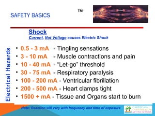
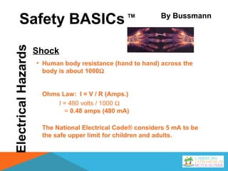
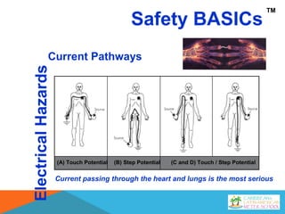
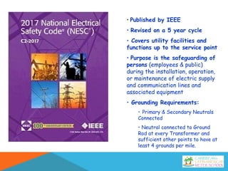
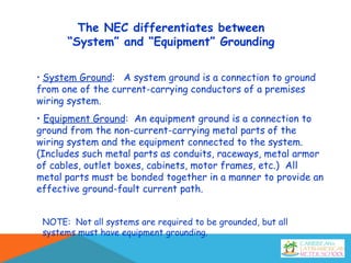
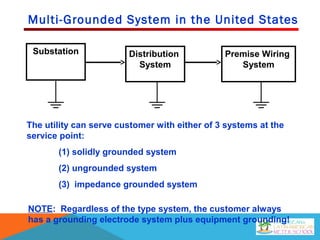
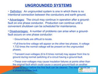
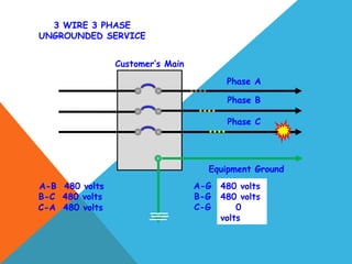
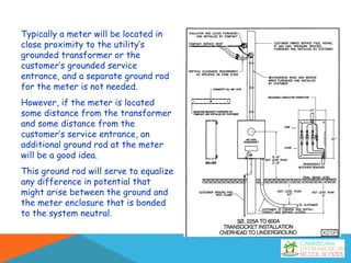
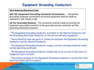
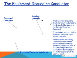
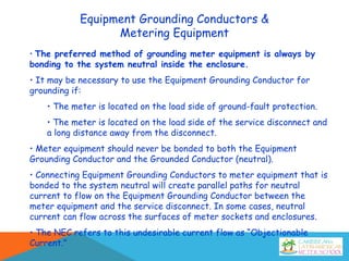
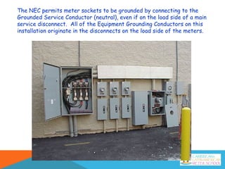
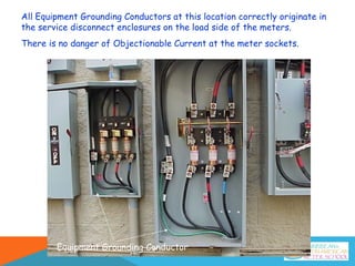
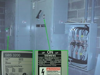
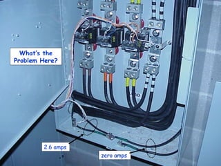
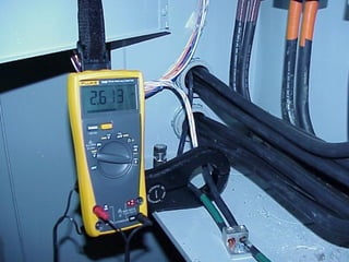
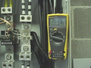
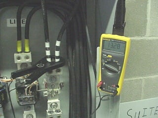
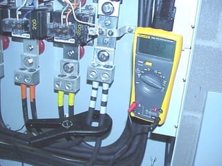
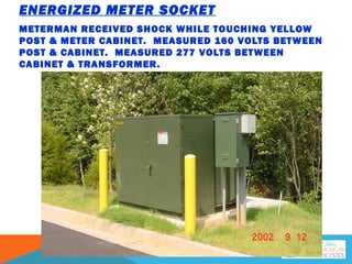
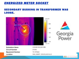
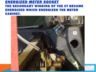
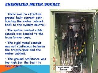
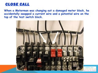
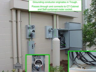
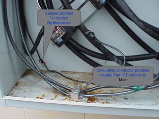
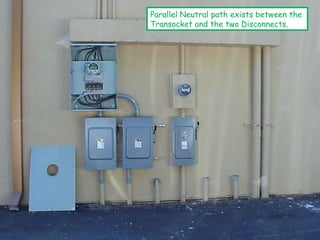
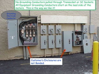
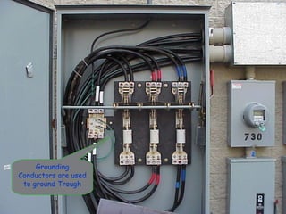
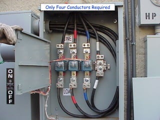
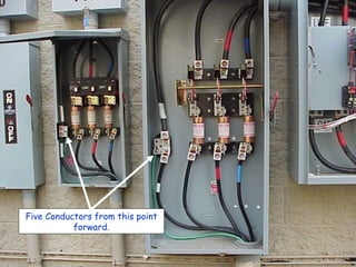
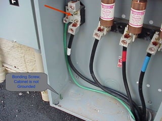
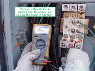
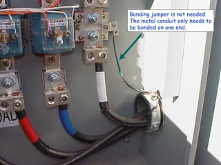
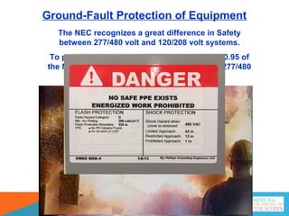
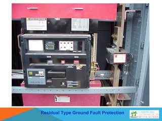
Grounding and Bonding
Georgia Power
Why Ground?
Following up after a major storm event Field Meter Tech arrived on site to
investigate Form 2S meter reporting low phase to phase voltage (124 volts).
The meter should normally report 240 volts.
Upon arrival he noted that recently a tree had fallen and possibly pulled
down the service. (he found out later an out of state crew had pulled the
cut in back up and re-attached the service)
While performing a socket check-out he found 119 volts from left hot leg to
neutral
He found 242 volts from right hot leg to neutral.
At that point he had an uneasy feeling something was very wrong. He stuck a
piece of #6 solid copper wire into the ground and measured from neutral to
the copper wire and got 84.2 volts. THE SOCKET ENCLOSURE WAS
ENERGIZED!
When the crew pulled
the service back up
they squeezed the
socket neutral
conductor to a hot leg
at the mast. And it
held! No fuses were
blown.
The neutral and one energized phase had been mistakenly crossed. This
created a very unsafe situation as the socket and mast were energized at
120 volts. The home was vacant at the time.
We do not know if the
premise suffered any
property damage due
to the voltage issue.
As you can see, the
socket has grounding
to a driven ground rod.
This was in a coastal
area with very sandy
soil. Evidently the
grounding was not
good enough to blow a
fuse and clear this up.
Why Ground?
Safety
Protecting person and property from
injury and damage
Facilitate the operation of protective
devices before damage occurs
Ensure the integrity of digital systems
and reliability of data
Equipment and Protection
Digital Stability
True or False?
• Electrons take the path of least resistance.
The truth is that electrons will take every
available path. (i.e. the human body, the surface of
meter enclosures, etc.)
• Electrons leaving a power supply are trying to flow to
earth.
The truth is that electrons are trying to return to
the power supply, not the earth. Electrons will use
the earth as one path if given the opportunity.
• The earth is a good conductor.
The truth is that the earth is often a very poor
conductor. It is difficult for the earth to conduct
enough current to clear a phase to ground fault.
FACTS
• Current will always return to the source
• Current will return in all paths that are available
• The amount of Current on a particular path depends
on the impedance of that path
SAFETY BASICS
ElectricalHazards TM
• 0.5 - 3 mA - Tingling sensations
• 3 - 10 mA - Muscle contractions and pain
• 10 - 40 mA - “Let-go” threshold
• 30 - 75 mA - Respiratory paralysis
• 100 - 200 mA - Ventricular fibrillation
• 200 - 500 mA - Heart clamps tight
• 1500 + mA - Tissue and Organs start to burn
Note: Reaction will vary with frequency and time of exposure
Shock
Current, Not Voltage causes Electric Shock
ElectricalHazardsSafety BASICs
Shock
• Human body resistance (hand to hand) across the
body is about 1000Ω
Ohms Law: I = V / R (Amps.)
I = 480 volts / 1000 Ω
= 0.48 amps (480 mA)
The National Electrical Code® considers 5 mA to be
the safe upper limit for children and adults.
TM By Bussmann
Safety BASICs
ElectricalHazards
Current Pathways
TM
(A) Touch Potential (B) Step Potential (C and D) Touch / Step Potential
Current passing through the heart and lungs is the most serious
• Published by IEEE
• Revised on a 5 year cycle
• Covers utility facilities and
functions up to the service point
• Purpose is the safeguarding of
persons (employees & public)
during the installation, operation,
or maintenance of electric supply
and communication lines and
associated equipment
• Grounding Requirements:
• Primary & Secondary Neutrals
Connected
• Neutral connected to Ground
Rod at every Transformer and
sufficient other points to have at
least 4 grounds per mile.
• Published by NFPA
• Revised on a 3 year cycle
• Covers Customer wiring systems
•Article 250 covers the grounding
and bonding requirements for
protection against fire hazards
and to assure personnel safety
from electrocution.
• Requirements include the
Equipment Grounding (bonding)
System, and the Grounding
Electrode System (earth ground)
NESC vs. NEC
Utility System
Covered by NESC
Customer Wiring Systems
Covered by NEC
(The electrical system in the USA is a
solidly multi-grounded system.)
(Most customer wiring systems are solidly
grounded systems, but may also be
ungrounded or high impedance grounded.)
(Both NEC and NESC may apply in industrial complex or multi-building complex)
Definitions
(NEC, Article 100 – Definitions)
Bonding (Bonded). “Connected to establish electrical continuity and conductivity.”
Bonding Jumper. “A reliable conductor to ensure the required electrical conductivity
between metal parts required to be electrically connected.”
Ground. “The earth.”
Grounded. “Connected to earth or to some conducting body that serves in place of
the earth.”
Grounded Conductor. “A system or circuit conductor that is intentionally
grounded.” (Commonly referred to as the neutral conductor. It should be white or
identified with white markings.)
Equipment Grounding Conductor. “The conductor used to connect the non-
current–carrying metal parts of equipment, raceways, and other enclosures to the
system grounded (neutral) conductor, the grounding electrode conductor, or both,
at the service equipment.” (Sometimes referred to as the Bond wire. It should
be green or identified with green markings.)
Grounding Electrode Conductor. “A conductor used to connect the system grounded
conductor or the equipment to a grounding electrode or to a point on the grounding
electrode system.”
Grounded
Conductor
Grounding Electrode Conductor
(Can connect to Grounded Conductor in
Main or at Weatherhead)
Equipment
Grounding
Conductor
Bonding
Jumpers
Definitions
The NEC differentiates between
“System” and “Equipment” Grounding
• System Ground: A system ground is a connection to ground
from one of the current-carrying conductors of a premises
wiring system.
• Equipment Ground: An equipment ground is a connection to
ground from the non-current-carrying metal parts of the
wiring system and the equipment connected to the system.
(Includes such metal parts as conduits, raceways, metal armor
of cables, outlet boxes, cabinets, motor frames, etc.) All
metal parts must be bonded together in a manner to provide an
effective ground-fault current path.
NOTE: Not all systems are required to be grounded, but all
systems must have equipment grounding.
Multi-Grounded System in the United States
Substation Distribution
System
Premise Wiring
System
The utility can serve customer with either of 3 systems at the
service point:
(1) solidly grounded system
(2) ungrounded system
(3) impedance grounded system
NOTE: Regardless of the type system, the customer always
has a grounding electrode system plus equipment grounding!
UNGROUNDED SYSTEMS
• Definition: An ungrounded system is one in which there is no
intentional connection between the conductors and earth ground.
• Advantages: The circuit may continue in operation after a ground-
fault on one phase conductor. Production can continue until a
convenient shutdown can be scheduled for maintenance.
• Disadvantages: A number of problems can arise when a ground-
fault occurs on one phase conductor:
• Ground-faults are difficult to locate.
• Full line-to-line voltage will appear on the other two phases. A voltage
1.732 times the normal voltage will be present on the ungrounded
phases.
• Transient over-voltages (6 to 8 times normal) may appear from line to
ground during normal switching of a circuit having a ground-fault.
• These over-voltages may cause insulation failures at points other than
the original fault which could cause a second ground-fault on another
phase to occur before the first fault can be cleared. The result would be
a phase-to-phase fault.
Customer’s Main
3 WIRE 3 PHASE
UNGROUNDED SERVICE
Phase A
Phase B
Phase C
Equipment Ground
A-B 480 volts
B-C 480 volts
C-A 480 volts
A-G Float
B-G Float
C-G Float
480 volts
480 volts
0
volts
HIGH IMPEDANCE GROUNDED SYSTEMS
• Definition: A high impedance grounded system is one that has the
neutral connected to ground through a resistance that will limit
ground-fault current to a very low level. (Typically under 10 amps)
• Advantages: As in ungrounded systems, the circuit may continue
in operation after a ground-fault on one phase conductor. By limiting
the ground-fault current, the fault can be tolerated on the system until
it can be located and removed. Transient over-voltages are limited
during ground-faults, and faults are easier to locate.
• Disadvantages: As in ungrounded systems, the two un-faulted
phases rise to the line-to-line voltage creating an increase in voltage
stress on the insulation of the system. Also, as in ungrounded
systems, should a second ground-fault occur on another phase
before the first ground-fault is removed, a line-to-line fault is created.
IMPEDANCE GROUNDED SYSTEMS
(250.36 & 250.187)
Large industrial customers have grounding
resistor banks in utility substation
Installations in 1500 - 2500 kVA range
have resistors in main switchboard
Installations served from padmount
transformer have to be modified
Identify transformers with special tag for
maintenance/safety reasons
PADMOUNT
TRANSFORMERS MUST
BE MODIFIED
CAUTION
Transformer has been modified.
When replacing this unit
remove HoX o link, GRD HV
coil and remove
Xo GRD strap.
Contact Corp. Distribution Dept.
A Typical Caution Sticker is Illustrated Below
TYPICAL TRANSFORMER TAG
Note the small neutral
conductor
IEEE Std 242-1986 Recommended Practice for
Protection and Coordination of Industrial and
Commercial Power Systems
7.2.5 Ungrounded systems offer no advantage over
high-resistance grounded systems in terms of
continuity of service, and have the disadvantage of
transient over-voltages, difficulty locating the first
ground fault, and burn downs from a second ground
fault. For these reasons, they are being used less
frequently today than high-resistance grounded
systems, and existing ungrounded systems are often
converted to high resistance grounded systems.
SOLIDLY GROUNDED SYSTEMS
A solidly grounded system is one in which the
neutral points have been intentionally
connected to earth ground with a conductor
having no intentional impedance.
(Solidly grounded systems are the most common type, and the
remainder of this presentation will focus on solidly ground systems.)
GROUNDED AND GROUNDING CONDUCTORS
BEFORE MAIN AFTER MAIN
TRANSFORMER MAIN PANEL SUBPANEL
MAIN
BONDING
JUMPER
EGNEGS/N
UTILITY
GROUNDING
ELECTRODE
SYSTEM
250.24(A)(2)
GROUNDED
CONDUCTOR
(NEUTRAL)
May be bare
250.24(B)
230.30 Ex
230.41 Ex
CUSTOMER
GROUNDING
ELECTRODE
SYSTEM
250.24(A)
NEUTRAL
(A CIRCUIT
CONDUCTOR)
Must be Insulated
beyond the Main
White or Gray or
3 Cont. white stripes
or marking 200.6 & 7
EQUIPMENT
GROUNDING
CONDUCTOR
(PATH TO
GROUND)
250.118 to 124
N
NN
EG
M
Note: The grounding electrode system may be connected to the grounded conductor at
either the Main Panel (S/N bus and EG bus are bonded together) or at the meter base
when the appropriate lug is provided , or at the weatherhead for overhead services.
SOLIDLY GROUNDED
SYSTEM - The most
common system
single phase
120/240 V
three-phase
240/120 V
208Y/120 V
480Y/277 V
special cases
600Y/346 V
Medium Voltage
4160Y2400 V
See IEEE
Red Book
Common Grounding when there is a lug in the Meter Base and
the Grounding Electrode Conductor originates from the Meter
Grounding Electrode
Conductor
Equipment Grounding
Conductors originate in
two main disconnects
Service Feeder Cable to “Main lugs only” Panels
Sub-panels fed from two outside “Mains”
Equipment Grounding
Conductor
(Isolated from Neutral)
2014 National Electrical Code
250.4 General Requirements for Grounding and Bonding.
(A) Grounded Systems.
(5) Effective Ground-Fault Current Path. Electrical equipment and wiring and
other electrically conductive material likely to become energized shall be installed in
a manner that creates a permanent, low-impedance circuit facilitating the operation
of the overcurrent device or ground detector for high-impedance grounded systems.
It shall be capable of safely carrying the maximum ground-fault current likely to be
imposed on it from any point on the wiring system where a ground fault may occur to
the electrical supply source. The earth shall not be used as the sole equipment
grounding conductor or effective ground-fault current path.
What does this mean in terms of grounding metering equipment?
All metering equipment (sockets, cabinets, conduits, etc.) must
be effectively bonded to the system neutral to prevent the
equipment from becoming energized in the case of a line to
ground fault.
Grounding to the earth only (ground rod) may not allow enough
current flow to clear the fault.
Effective Ground Fault Current Path
Earth Grounding alone will not Remove Dangerous Voltage
Caused by Line-to-Case Faults
A ground rod with 25 ohms of
resistance would only allow 4.8
amperes of current flow in the
event of a 120 volt to ground fault.
I =
E
R
= 4.8 A
120 V
25 ohms
Remember: current will take every available
path, including you!
Effective Ground
Fault Current Path
Self-contained
Sockets
• Self-contained meter
enclosures are typically
bonded to the grounded
conductor (neutral) by
design.
• No other grounding
conductors or bonding
jumpers are required to
provide an effective ground
fault current path.
Effective Ground
Fault Current Path
Transformer Rated
Meter Installations
• All metal enclosures and
conduits must be bonded with
a good low impedance path to
the system neutral.
• If the meter control cable
conduit is used for the
bonding path, a proper bond
must exist between the
conduit and the meter
enclosure.
Effective Ground Fault
Current Path
If the conduit is not used for
the bonding path, a bond wire
can be pulled inside the
conduit.
This will be necessary if using
PVC conduit for the meter
control cable.
The bond wire should be larger
than the size of the meter
control wires.
If pulling a bond wire inside
metal conduit, bond the wire
to one end of the conduit.
Preferably the meter end.
Some Utilities specify a Ground
Rod at all meter installations.
This Ground Rod must not be depended upon
for clearing dangerous voltage which may
result from a line to ground fault within the
metering equipment.
If not for fault protection, what is the purpose of Ground Rods?
The electrical system is grounded to earth to limit voltages due to
lightning, line surges, or unintentional contact with higher voltage lines.
The ground rod provides a
connection to earth to assist in
dissipating lightning into the earth
without severely damaging the
electrical equipment.
Earth grounding also
helps to stabilize the
voltage to ground during
normal operation.
Typically a meter will be located in
close proximity to the utility’s
grounded transformer or the
customer’s grounded service
entrance, and a separate ground rod
for the meter is not needed.
However, if the meter is located
some distance from the transformer
and some distance from the
customer’s service entrance, an
additional ground rod at the meter
will be a good idea.
This ground rod will serve to equalize
any difference in potential that
might arise between the ground and
the meter enclosure that is bonded
to the system neutral.
Equipment Grounding Conductors
2014 National Electrical Code
250.130 Equipment Grounding Conductor Connections. …Equipment
grounding conductor connections at service equipment shall be made as
indicated in 250.130(A) or (B)...
(A) For Grounded Systems. The connection shall be made by bonding the
equipment grounding conductor to the grounded service conductor and the
grounding electrode conductor.
• The Equipment Grounding Conductor is bonded to the Neutral Conductor and
the Grounding Electrode Conductor at the service entrance equipment.
• There should be only one point of connection between the Equipment Grounding
Conductor and the Neutral Conductor.
• The Equipment Grounding Conductor is not a current carrying conductor under
normal operating conditions.
• The Equipment Grounding Conductor should only carry current in the event of
temporary fault currents.
• The primary purpose of the Equipment Grounding Conductor is protection from
electrical shock and fire hazard.
• The secondary purpose is to provide a stable reference for electronic
equipment.
Grounded
Conductor
Grounding Electrode Conductor
The Equipment Grounding
Conductor must be bonded to
the Grounded Conductor at
the Service Entrance
Equipment.
It must never connect to the
grounded conductor again
beyond this point.
The Equipment Grounding
Conductor is considered
bonded to the Grounding
Electrode Conductor even if
the Grounding Electrode
conductor is terminated in
the meter socket or at the
weather head..
Bonding
Jumpers
The Equipment Grounding Conductor
Equipment Grounding Conductors &
Metering Equipment
• The preferred method of grounding meter equipment is always by
bonding to the system neutral inside the enclosure.
• It may be necessary to use the Equipment Grounding Conductor for
grounding if:
• The meter is located on the load side of ground-fault protection.
• The meter is located on the load side of the service disconnect and
a long distance away from the disconnect.
• Meter equipment should never be bonded to both the Equipment
Grounding Conductor and the Grounded Conductor (neutral).
• Connecting Equipment Grounding Conductors to meter equipment that is
bonded to the system neutral will create parallel paths for neutral
current to flow on the Equipment Grounding Conductor between the
meter equipment and the service disconnect. In some cases, neutral
current can flow across the surfaces of meter sockets and enclosures.
• The NEC refers to this undesirable current flow as “Objectionable
Current.”
Self-Contained Sockets
are typically bonded to
the Neutral by design.
An Equipment Grounding
Conductor should not
attach to a meter
enclosure when the
enclosure is bonded to
the system neutral.
Exception: If the meter is
installed on the load side of
ground-fault protection, the
enclosure may need to be
grounded by the equipment
grounding conductor, rather
than the system neutral.
Equipment Grounding Conductor
2014 National Electrical Code
250.6 Objectionable Current over Grounding Conductors.
(A) Arrangement to Prevent Objectionable Current. The grounding of electrical systems,
circuit conductors, surge arresters, surge-protection devices, and conductive normally
non-current-carrying metal parts of equipment shall be installed and arranged in a manner
that will prevent objectionable current.
(B) Alterations to Stop Objectionable Current. If the use of multiple grounding
connections results in objectionable current, one or more of the following alterations shall
be permitted to be made, provided that the requirements of 250.4(A)(5) or (B)(4) are met:
(1) Discontinue one or more but not all of such grounding connections.
(2) Change the locations of the grounding connections.
(3) Interrupt the continuity of the conductor or conductive path causing the objectionable
current.
(4) Take other suitable remedial and approved action.
What does this mean in respect to metering equipment?
Parallel paths for the flow of neutral current should not exist across the
surface of meter equipment, or be allowed to flow through equipment grounding
conductors inside metering enclosures.
Danger of Objectionable
Current on the Grounding Path
• Electric Shock. Electric shock can occur if a person gets in series with a
grounding path that is carrying objectionable current. We do not normally
expect current to be on ground wires. A grounding conductor carrying
objectionable current can be especially dangerous in the event of a loose or
broken neutral connection. The grounding conductor carrying objectionable
current could be a metal raceway, and a person opening the raceway could be
killed.
• Fire Hazard. Neutral current on the grounding path can cause
temperature to build up on the grounding conductor and/or at loose
connections. A poor connection on the system neutral could cause excessive
current and heating or arcing on the grounding path.
• Power Quality Issues. Currents flowing on the grounding path and
across the surfaces of equipment can cause electrical noise that may
adversely effect sensitive electronic equipment.
Objectionable currents due to multiple neutral-to-ground connections
are often present at installations with multiple meters, especially when
there is a main disconnect ahead of the meters.
The NEC permits meter sockets to be grounded by connecting to the
Grounded Service Conductor (neutral), even if on the load side of a main
service disconnect. All of the Equipment Grounding Conductors on this
installation originate in the disconnects on the load side of the meters.
All Equipment Grounding Conductors at this location correctly originate in
the service disconnect enclosures on the load side of the meters.
There is no danger of Objectionable Current at the meter sockets.
Equipment Grounding Conductor
2014 National Electrical Code
250.142 Use of Grounded Circuit Conductor for Grounding Equipment
(A) Supply-Side Equipment. A grounded circuit conductor shall be permitted to ground
non-current-carrying metal parts of equipment, raceways, and other enclosures at
any of the following locations:
(1) On the supply side or within the enclosure of the ac service-disconnecting means.
(B) Load-Side Equipment. …a grounded circuit conductor shall not be used for
grounding non-current-carrying metal parts of equipment on the load side of the
service disconnecting means…
Exception No. 2: It shall be permissible to ground meter enclosures by connection to
the grounded circuit conductor on the load side of the service disconnect where all of
the following conditions apply:
(a) No service ground-fault protection is installed.
(b) All meter enclosures are located immediately adjacent to the service disconnecting
means.
(c) The size of the grounded circuit conductor is not smaller than the size specified in
Table 250.122 for equipment grounding conductors.
The NEC allows for the grounding of Metering Equipment by bonding the
Meter Enclosure to the Grounded Conductor (neutral) inside the Enclosure,
Even when the Meter Enclosure is on the Load Side of a Main Service
Disconnect.
Bonding of Service Equipment
Section 250.92 of the NEC, which addresses the bonding together of
all service entrance equipment, also allows for Meter Enclosures to be
grounded by bonding to the Grounded Conductor (neutral) inside the
enclosure without the need for any additional grounding conductors or
bonding jumpers.
2014 National Electrical Code
250.92 (A) Bonding of Services. The normally non-current-carrying metal parts of equipment
indicated in 250.92(A)(1) and (A)(2) shall be bonded together.
(1) All raceways, cables trays, cablebus framework, auxiliary gutters, or service cable armor or
sheath that enclose, contain, or support service conductors, except as permitted in 250.80.
(2) All enclosures containing service conductors, including meter fittings, boxes, or the like,
interposed in the service raceway or armor.
(B) Method of Bonding at the Service. Electrical continuity at service equipment, service
raceways, and service conductor enclosures shall be ensured by one of the following
methods:
(1) Bonding equipment to the grounded service conductor in a manner provided in 250.8
Effective Ground Fault Current Path
Earth Grounding alone will not Remove Dangerous Voltage
Caused by Line-to-Case Faults
• Copper thieves had already
stripped out equipment grounding
conductors and bonding jumpers.
• This left the installation without an
effective low impedance ground fault
current path.
• When the thieves attempted to cut
the energized phase conductors, the
cable cutters welded against the
metal enclosure.
• The fault current’s only path back
to the transformer was through the
ground.
• The customer had not operated this plant for several years and there had been no
electrical energy consumption.
• The customer suddenly received a bill for over 30,000 kWH of energy consumption.
• It was determined that the cable cutters were carrying a 27 kW load. (approx. 97 amps)
SERVICE
DISCONNECT CT CABINET
S.C.
TRANSOCKET
“It shall be permissible to ground meter enclosures by connection to the grounded
circuit conductor on the load side of the service disconnect if
(a) No service ground-fault protection is installed, and
(b) All meter enclosures are located immediately adjacent to the service
disconnecting means” NEC Section
250.142 (B) Exception No. 2
With a few rare exceptions, customer equipment grounding conductors
should not connect to or pass through meter enclosures – even when a
service disconnect is ahead of the meters.
Four Conductors
From Utility
Grounding
Electrode
Conductor
All non-current-carrying metal parts of this Service are individually
Bonded to the Grounded (Neutral) Conductor inside each enclosure.
All metal parts are “Effectively” Bonded together.
All PVC Conduit
All Equipment Grounding Conductors
Originate on the Load Side of each
Disconnect. Five Conductors from this
point forward.
All Equipment Grounding Conductors
Originate on the Load Side of each
Disconnect. Five Conductors from this
point forward.
Grounded
Conductor
Grounding Electrode Conductor
Section 250.92 of the NEC is
sometimes misunderstood when
metal conduit is installed
between enclosures. Some
electricians may think that the
bonding of the enclosures must
be through the conduit.
Section 250.92 states that all
service enclosures are
effectively bonded together if
each enclosure is bonded to
the Grounded Conductor.
Metal conduits housing service
conductors only need to be
bonded on one end.
Bonding jumpers are not
needed inside the meter
enclosure.
Bonding
Jumpers
Bonding of Service Equipment
Equipment Grounding Conductor originates in
Transocket. Parallel neutral paths exist due to
multiple neutral to ground connections.
Service
Neutral Current on Equipment
Grounding Conductor due to Neutral
to Ground connection in Transocket
2.6 amps
zero amps
What’s the
Problem Here?
ENERGIZED METER SOCKET
METERMAN RECEIVED SHOCK WHILE TOUCHING YELLOW
POST & METER CABINET. MEASURED 160 VOLTS BETWEEN
POST & CABINET. MEASURED 277 VOLTS BETWEEN
CABINET & TRANSFORMER.
ENERGIZED METER SOCKET
SECONDARY BUSHING IN TRANSFORMER WAS
LOOSE.
ENERGIZED METER SOCKET
THE SECONDARY WINDING OF THE CT BECAME
ENERGIZED WHICH ENERGIZED THE METER
CABINET.
ENERGIZED METER SOCKET
• There was no effective
ground fault current path
bonding the meter cabinet
back to the system neutral.
• The meter control cable
conduit was bonded to the
transformer case.
• The rigid metal conduit
was not continuous between
the transformer and the
meter cabinet.
• The ground resistance was
too high for the fault to
clear itself. Rigid Metal
Conduit
CLOSE CALL
When a Meterman was changing out a damaged meter block, he
accidentally swapped a current wire and a potential wire on the
top of the test switch block.
The current and voltage wires were crossed on the third
phase. The right-hand current coil in the meter was
energized at 277 volts. Because the current returns are
grounded, the meter socket was momentarily energized before
the fault cleared itself.
This installation had an Effective Ground Fault Current
Path!
THE #6 GROUND WIRE DID ITS JOB
When the meterman closed the test switches, the orange
potential wire in the meter control cable quickly heated, melting
its insulation along the entire length. The individual strands were
actually welded together.
The meter control wires
shorted phase-to-phase
inside the pad-mount
transformer and cleared
the fault so that the
meter socket was not
left energized.
Note: These are two
good examples of why we
ground the secondary side
of instrument
transformers.
Equipment Grounding Conductor attaches to and passes through
CT cabinet back to UG Transformer. A parallel neutral path
exists from the GPC transformer to the main disconnect.
Amps on Neutral
Amps on Grounding Conductor
The Equipment Grounding
Conductor is correctly
connected to the
Grounded Conductor
inside the service
disconnect on the load
side of the meter.
There should be no other
neutral-to-ground
connection beyond this
point.
Grounding conductor passes through CT
Cabinet to Neutral Spade in Transformer.
Parallel neutral path exists from transformer to
main disconnect inside.
Grounding conductor originates in Trough.
Passes through and connects to CT Cabinet
and Self-contained meter socket.
Service
Grounding conductor parallels
neutral from CT cabinet to
Main
Cabinet Bonded
To Neutral
By Meterman
Parallel Neutral path exists between the
Transocket and the two Disconnects.
No Grounding Conductors pulled through Transocket or SC Sockets.
All Equipment Grounding Conductors start on the load side of the
meters. This is the way we like it!
Grounding
Electrode
Conductor
Customer’s Enclosures are
not Bonded.
Grounding
Conductors are used
to ground Trough
Only Four Conductors Required
Five Conductors from this point
forward.
Bonding Screw,
Cabinet is not
Grounded
Customer’s Main Cabinet is
isolated from the neutral bus.
How did the inspector miss this?
Bonding jumper is not needed.
The metal conduit only needs to
be bonded on one end.
The NEC recognizes a great difference in Safety
between 277/480 volt and 120/208 volt systems.
To prevent arc faults or arc flashes, Article 230.95 of
the NEC requires Ground-Fault Protection on 277/480
systems rated 1000 amperes or greater.
Ground-Fault Protection of Equipment
IEEE Std 242-1986 Recommended Practice for Protection and
Coordination of Industrial and Commercial Power Systems.
7.2.2 One disadvantage of the solidly grounded 480 V systems
involves the high magnitude of ground-fault currents that can
occur, and the destructive nature of arcing ground faults.
IEEE Std 141-1993 Recommended Practice for Electric Power
Distribution for Industrial Plants
7.2.4 The solidly grounded system has the highest probability of
escalating into a phase-to-phase or three-phase arcing fault,
particularly for the 480 and 600V systems. A safety hazard exists
for solidly grounded systems from the severe flash, arc burning and
blast hazard from any phase-to-ground fault.
What does IEEE say?
NEC Article 100 - Definitions: Ground-Fault Protection of Equipment
“A system intended to provide protection of equipment from damaging line-to-
ground fault currents by operating to cause a disconnecting means to open all
ungrounded conductors of the faulted circuit. This protection is provided at
current levels less than those required to protect conductors from damage
through the operation of a supply circuit overcurrent device.”
NEC Article 230.95 Ground-Fault Protection of Equipment
“Ground-fault protection of equipment shall be provided for solidly grounded
wye electrical services of more than 150 volts to ground but not exceeding
1000 volts phase-to-phase for each service disconnect rated 1000 amperes
or more.”
• The reason behind this requirement was an awareness of the danger of arc
faults on grounded 277/480 volt systems.
• On larger services, the current required to sustain the arc may be less than the
rating of the circuit breakers.
• On smaller services (below 1000 amps), the overcurrent devices would be
expected to clear the fault in sufficient time to limit damage, however, ground-
fault protection may sometimes be desirable on services below 1000 amps.
• Up to six 800 amp mains may be installed without GFP.
The Ground-fault sensor is installed around all the circuit
conductors, including the neutral.
The Ground-fault sensor is installed around the
bonding jumper only.
Residual Type Ground Fault Protection
The End

Grounding and Bonding

  • 1.
  • 2.
  • 3.
    Following up aftera major storm event Field Meter Tech arrived on site to investigate Form 2S meter reporting low phase to phase voltage (124 volts). The meter should normally report 240 volts. Upon arrival he noted that recently a tree had fallen and possibly pulled down the service. (he found out later an out of state crew had pulled the cut in back up and re-attached the service)
  • 4.
    While performing asocket check-out he found 119 volts from left hot leg to neutral
  • 5.
    He found 242volts from right hot leg to neutral.
  • 6.
    At that pointhe had an uneasy feeling something was very wrong. He stuck a piece of #6 solid copper wire into the ground and measured from neutral to the copper wire and got 84.2 volts. THE SOCKET ENCLOSURE WAS ENERGIZED! When the crew pulled the service back up they squeezed the socket neutral conductor to a hot leg at the mast. And it held! No fuses were blown.
  • 7.
    The neutral andone energized phase had been mistakenly crossed. This created a very unsafe situation as the socket and mast were energized at 120 volts. The home was vacant at the time. We do not know if the premise suffered any property damage due to the voltage issue. As you can see, the socket has grounding to a driven ground rod. This was in a coastal area with very sandy soil. Evidently the grounding was not good enough to blow a fuse and clear this up.
  • 8.
    Why Ground? Safety Protecting personand property from injury and damage Facilitate the operation of protective devices before damage occurs Ensure the integrity of digital systems and reliability of data Equipment and Protection Digital Stability
  • 9.
    True or False? •Electrons take the path of least resistance. The truth is that electrons will take every available path. (i.e. the human body, the surface of meter enclosures, etc.) • Electrons leaving a power supply are trying to flow to earth. The truth is that electrons are trying to return to the power supply, not the earth. Electrons will use the earth as one path if given the opportunity. • The earth is a good conductor. The truth is that the earth is often a very poor conductor. It is difficult for the earth to conduct enough current to clear a phase to ground fault.
  • 10.
    FACTS • Current willalways return to the source • Current will return in all paths that are available • The amount of Current on a particular path depends on the impedance of that path
  • 11.
    SAFETY BASICS ElectricalHazards TM •0.5 - 3 mA - Tingling sensations • 3 - 10 mA - Muscle contractions and pain • 10 - 40 mA - “Let-go” threshold • 30 - 75 mA - Respiratory paralysis • 100 - 200 mA - Ventricular fibrillation • 200 - 500 mA - Heart clamps tight • 1500 + mA - Tissue and Organs start to burn Note: Reaction will vary with frequency and time of exposure Shock Current, Not Voltage causes Electric Shock
  • 12.
    ElectricalHazardsSafety BASICs Shock • Humanbody resistance (hand to hand) across the body is about 1000Ω Ohms Law: I = V / R (Amps.) I = 480 volts / 1000 Ω = 0.48 amps (480 mA) The National Electrical Code® considers 5 mA to be the safe upper limit for children and adults. TM By Bussmann
  • 13.
    Safety BASICs ElectricalHazards Current Pathways TM (A)Touch Potential (B) Step Potential (C and D) Touch / Step Potential Current passing through the heart and lungs is the most serious
  • 14.
    • Published byIEEE • Revised on a 5 year cycle • Covers utility facilities and functions up to the service point • Purpose is the safeguarding of persons (employees & public) during the installation, operation, or maintenance of electric supply and communication lines and associated equipment • Grounding Requirements: • Primary & Secondary Neutrals Connected • Neutral connected to Ground Rod at every Transformer and sufficient other points to have at least 4 grounds per mile.
  • 15.
    • Published byNFPA • Revised on a 3 year cycle • Covers Customer wiring systems •Article 250 covers the grounding and bonding requirements for protection against fire hazards and to assure personnel safety from electrocution. • Requirements include the Equipment Grounding (bonding) System, and the Grounding Electrode System (earth ground)
  • 16.
    NESC vs. NEC UtilitySystem Covered by NESC Customer Wiring Systems Covered by NEC (The electrical system in the USA is a solidly multi-grounded system.) (Most customer wiring systems are solidly grounded systems, but may also be ungrounded or high impedance grounded.) (Both NEC and NESC may apply in industrial complex or multi-building complex)
  • 17.
    Definitions (NEC, Article 100– Definitions) Bonding (Bonded). “Connected to establish electrical continuity and conductivity.” Bonding Jumper. “A reliable conductor to ensure the required electrical conductivity between metal parts required to be electrically connected.” Ground. “The earth.” Grounded. “Connected to earth or to some conducting body that serves in place of the earth.” Grounded Conductor. “A system or circuit conductor that is intentionally grounded.” (Commonly referred to as the neutral conductor. It should be white or identified with white markings.) Equipment Grounding Conductor. “The conductor used to connect the non- current–carrying metal parts of equipment, raceways, and other enclosures to the system grounded (neutral) conductor, the grounding electrode conductor, or both, at the service equipment.” (Sometimes referred to as the Bond wire. It should be green or identified with green markings.) Grounding Electrode Conductor. “A conductor used to connect the system grounded conductor or the equipment to a grounding electrode or to a point on the grounding electrode system.”
  • 18.
    Grounded Conductor Grounding Electrode Conductor (Canconnect to Grounded Conductor in Main or at Weatherhead) Equipment Grounding Conductor Bonding Jumpers Definitions
  • 19.
    The NEC differentiatesbetween “System” and “Equipment” Grounding • System Ground: A system ground is a connection to ground from one of the current-carrying conductors of a premises wiring system. • Equipment Ground: An equipment ground is a connection to ground from the non-current-carrying metal parts of the wiring system and the equipment connected to the system. (Includes such metal parts as conduits, raceways, metal armor of cables, outlet boxes, cabinets, motor frames, etc.) All metal parts must be bonded together in a manner to provide an effective ground-fault current path. NOTE: Not all systems are required to be grounded, but all systems must have equipment grounding.
  • 20.
    Multi-Grounded System inthe United States Substation Distribution System Premise Wiring System The utility can serve customer with either of 3 systems at the service point: (1) solidly grounded system (2) ungrounded system (3) impedance grounded system NOTE: Regardless of the type system, the customer always has a grounding electrode system plus equipment grounding!
  • 21.
    UNGROUNDED SYSTEMS • Definition:An ungrounded system is one in which there is no intentional connection between the conductors and earth ground. • Advantages: The circuit may continue in operation after a ground- fault on one phase conductor. Production can continue until a convenient shutdown can be scheduled for maintenance. • Disadvantages: A number of problems can arise when a ground- fault occurs on one phase conductor: • Ground-faults are difficult to locate. • Full line-to-line voltage will appear on the other two phases. A voltage 1.732 times the normal voltage will be present on the ungrounded phases. • Transient over-voltages (6 to 8 times normal) may appear from line to ground during normal switching of a circuit having a ground-fault. • These over-voltages may cause insulation failures at points other than the original fault which could cause a second ground-fault on another phase to occur before the first fault can be cleared. The result would be a phase-to-phase fault.
  • 22.
    Customer’s Main 3 WIRE3 PHASE UNGROUNDED SERVICE Phase A Phase B Phase C Equipment Ground A-B 480 volts B-C 480 volts C-A 480 volts A-G Float B-G Float C-G Float 480 volts 480 volts 0 volts
  • 23.
    HIGH IMPEDANCE GROUNDEDSYSTEMS • Definition: A high impedance grounded system is one that has the neutral connected to ground through a resistance that will limit ground-fault current to a very low level. (Typically under 10 amps) • Advantages: As in ungrounded systems, the circuit may continue in operation after a ground-fault on one phase conductor. By limiting the ground-fault current, the fault can be tolerated on the system until it can be located and removed. Transient over-voltages are limited during ground-faults, and faults are easier to locate. • Disadvantages: As in ungrounded systems, the two un-faulted phases rise to the line-to-line voltage creating an increase in voltage stress on the insulation of the system. Also, as in ungrounded systems, should a second ground-fault occur on another phase before the first ground-fault is removed, a line-to-line fault is created.
  • 24.
    IMPEDANCE GROUNDED SYSTEMS (250.36& 250.187) Large industrial customers have grounding resistor banks in utility substation Installations in 1500 - 2500 kVA range have resistors in main switchboard Installations served from padmount transformer have to be modified Identify transformers with special tag for maintenance/safety reasons
  • 25.
    PADMOUNT TRANSFORMERS MUST BE MODIFIED CAUTION Transformerhas been modified. When replacing this unit remove HoX o link, GRD HV coil and remove Xo GRD strap. Contact Corp. Distribution Dept. A Typical Caution Sticker is Illustrated Below
  • 26.
    TYPICAL TRANSFORMER TAG Notethe small neutral conductor
  • 27.
    IEEE Std 242-1986Recommended Practice for Protection and Coordination of Industrial and Commercial Power Systems 7.2.5 Ungrounded systems offer no advantage over high-resistance grounded systems in terms of continuity of service, and have the disadvantage of transient over-voltages, difficulty locating the first ground fault, and burn downs from a second ground fault. For these reasons, they are being used less frequently today than high-resistance grounded systems, and existing ungrounded systems are often converted to high resistance grounded systems.
  • 28.
    SOLIDLY GROUNDED SYSTEMS Asolidly grounded system is one in which the neutral points have been intentionally connected to earth ground with a conductor having no intentional impedance. (Solidly grounded systems are the most common type, and the remainder of this presentation will focus on solidly ground systems.)
  • 29.
    GROUNDED AND GROUNDINGCONDUCTORS BEFORE MAIN AFTER MAIN TRANSFORMER MAIN PANEL SUBPANEL MAIN BONDING JUMPER EGNEGS/N UTILITY GROUNDING ELECTRODE SYSTEM 250.24(A)(2) GROUNDED CONDUCTOR (NEUTRAL) May be bare 250.24(B) 230.30 Ex 230.41 Ex CUSTOMER GROUNDING ELECTRODE SYSTEM 250.24(A) NEUTRAL (A CIRCUIT CONDUCTOR) Must be Insulated beyond the Main White or Gray or 3 Cont. white stripes or marking 200.6 & 7 EQUIPMENT GROUNDING CONDUCTOR (PATH TO GROUND) 250.118 to 124 N NN EG M Note: The grounding electrode system may be connected to the grounded conductor at either the Main Panel (S/N bus and EG bus are bonded together) or at the meter base when the appropriate lug is provided , or at the weatherhead for overhead services. SOLIDLY GROUNDED SYSTEM - The most common system single phase 120/240 V three-phase 240/120 V 208Y/120 V 480Y/277 V special cases 600Y/346 V Medium Voltage 4160Y2400 V See IEEE Red Book
  • 30.
    Common Grounding whenthere is a lug in the Meter Base and the Grounding Electrode Conductor originates from the Meter Grounding Electrode Conductor Equipment Grounding Conductors originate in two main disconnects
  • 31.
    Service Feeder Cableto “Main lugs only” Panels Sub-panels fed from two outside “Mains” Equipment Grounding Conductor (Isolated from Neutral)
  • 32.
    2014 National ElectricalCode 250.4 General Requirements for Grounding and Bonding. (A) Grounded Systems. (5) Effective Ground-Fault Current Path. Electrical equipment and wiring and other electrically conductive material likely to become energized shall be installed in a manner that creates a permanent, low-impedance circuit facilitating the operation of the overcurrent device or ground detector for high-impedance grounded systems. It shall be capable of safely carrying the maximum ground-fault current likely to be imposed on it from any point on the wiring system where a ground fault may occur to the electrical supply source. The earth shall not be used as the sole equipment grounding conductor or effective ground-fault current path. What does this mean in terms of grounding metering equipment? All metering equipment (sockets, cabinets, conduits, etc.) must be effectively bonded to the system neutral to prevent the equipment from becoming energized in the case of a line to ground fault. Grounding to the earth only (ground rod) may not allow enough current flow to clear the fault.
  • 33.
    Effective Ground FaultCurrent Path Earth Grounding alone will not Remove Dangerous Voltage Caused by Line-to-Case Faults A ground rod with 25 ohms of resistance would only allow 4.8 amperes of current flow in the event of a 120 volt to ground fault. I = E R = 4.8 A 120 V 25 ohms Remember: current will take every available path, including you!
  • 34.
    Effective Ground Fault CurrentPath Self-contained Sockets • Self-contained meter enclosures are typically bonded to the grounded conductor (neutral) by design. • No other grounding conductors or bonding jumpers are required to provide an effective ground fault current path.
  • 35.
    Effective Ground Fault CurrentPath Transformer Rated Meter Installations • All metal enclosures and conduits must be bonded with a good low impedance path to the system neutral. • If the meter control cable conduit is used for the bonding path, a proper bond must exist between the conduit and the meter enclosure.
  • 36.
    Effective Ground Fault CurrentPath If the conduit is not used for the bonding path, a bond wire can be pulled inside the conduit. This will be necessary if using PVC conduit for the meter control cable. The bond wire should be larger than the size of the meter control wires. If pulling a bond wire inside metal conduit, bond the wire to one end of the conduit. Preferably the meter end.
  • 37.
    Some Utilities specifya Ground Rod at all meter installations. This Ground Rod must not be depended upon for clearing dangerous voltage which may result from a line to ground fault within the metering equipment.
  • 38.
    If not forfault protection, what is the purpose of Ground Rods? The electrical system is grounded to earth to limit voltages due to lightning, line surges, or unintentional contact with higher voltage lines. The ground rod provides a connection to earth to assist in dissipating lightning into the earth without severely damaging the electrical equipment. Earth grounding also helps to stabilize the voltage to ground during normal operation.
  • 39.
    Typically a meterwill be located in close proximity to the utility’s grounded transformer or the customer’s grounded service entrance, and a separate ground rod for the meter is not needed. However, if the meter is located some distance from the transformer and some distance from the customer’s service entrance, an additional ground rod at the meter will be a good idea. This ground rod will serve to equalize any difference in potential that might arise between the ground and the meter enclosure that is bonded to the system neutral.
  • 40.
    Equipment Grounding Conductors 2014National Electrical Code 250.130 Equipment Grounding Conductor Connections. …Equipment grounding conductor connections at service equipment shall be made as indicated in 250.130(A) or (B)... (A) For Grounded Systems. The connection shall be made by bonding the equipment grounding conductor to the grounded service conductor and the grounding electrode conductor. • The Equipment Grounding Conductor is bonded to the Neutral Conductor and the Grounding Electrode Conductor at the service entrance equipment. • There should be only one point of connection between the Equipment Grounding Conductor and the Neutral Conductor. • The Equipment Grounding Conductor is not a current carrying conductor under normal operating conditions. • The Equipment Grounding Conductor should only carry current in the event of temporary fault currents. • The primary purpose of the Equipment Grounding Conductor is protection from electrical shock and fire hazard. • The secondary purpose is to provide a stable reference for electronic equipment.
  • 41.
    Grounded Conductor Grounding Electrode Conductor TheEquipment Grounding Conductor must be bonded to the Grounded Conductor at the Service Entrance Equipment. It must never connect to the grounded conductor again beyond this point. The Equipment Grounding Conductor is considered bonded to the Grounding Electrode Conductor even if the Grounding Electrode conductor is terminated in the meter socket or at the weather head.. Bonding Jumpers The Equipment Grounding Conductor
  • 42.
    Equipment Grounding Conductors& Metering Equipment • The preferred method of grounding meter equipment is always by bonding to the system neutral inside the enclosure. • It may be necessary to use the Equipment Grounding Conductor for grounding if: • The meter is located on the load side of ground-fault protection. • The meter is located on the load side of the service disconnect and a long distance away from the disconnect. • Meter equipment should never be bonded to both the Equipment Grounding Conductor and the Grounded Conductor (neutral). • Connecting Equipment Grounding Conductors to meter equipment that is bonded to the system neutral will create parallel paths for neutral current to flow on the Equipment Grounding Conductor between the meter equipment and the service disconnect. In some cases, neutral current can flow across the surfaces of meter sockets and enclosures. • The NEC refers to this undesirable current flow as “Objectionable Current.”
  • 43.
    Self-Contained Sockets are typicallybonded to the Neutral by design. An Equipment Grounding Conductor should not attach to a meter enclosure when the enclosure is bonded to the system neutral. Exception: If the meter is installed on the load side of ground-fault protection, the enclosure may need to be grounded by the equipment grounding conductor, rather than the system neutral. Equipment Grounding Conductor
  • 44.
    2014 National ElectricalCode 250.6 Objectionable Current over Grounding Conductors. (A) Arrangement to Prevent Objectionable Current. The grounding of electrical systems, circuit conductors, surge arresters, surge-protection devices, and conductive normally non-current-carrying metal parts of equipment shall be installed and arranged in a manner that will prevent objectionable current. (B) Alterations to Stop Objectionable Current. If the use of multiple grounding connections results in objectionable current, one or more of the following alterations shall be permitted to be made, provided that the requirements of 250.4(A)(5) or (B)(4) are met: (1) Discontinue one or more but not all of such grounding connections. (2) Change the locations of the grounding connections. (3) Interrupt the continuity of the conductor or conductive path causing the objectionable current. (4) Take other suitable remedial and approved action. What does this mean in respect to metering equipment? Parallel paths for the flow of neutral current should not exist across the surface of meter equipment, or be allowed to flow through equipment grounding conductors inside metering enclosures.
  • 45.
    Danger of Objectionable Currenton the Grounding Path • Electric Shock. Electric shock can occur if a person gets in series with a grounding path that is carrying objectionable current. We do not normally expect current to be on ground wires. A grounding conductor carrying objectionable current can be especially dangerous in the event of a loose or broken neutral connection. The grounding conductor carrying objectionable current could be a metal raceway, and a person opening the raceway could be killed. • Fire Hazard. Neutral current on the grounding path can cause temperature to build up on the grounding conductor and/or at loose connections. A poor connection on the system neutral could cause excessive current and heating or arcing on the grounding path. • Power Quality Issues. Currents flowing on the grounding path and across the surfaces of equipment can cause electrical noise that may adversely effect sensitive electronic equipment.
  • 46.
    Objectionable currents dueto multiple neutral-to-ground connections are often present at installations with multiple meters, especially when there is a main disconnect ahead of the meters.
  • 47.
    The NEC permitsmeter sockets to be grounded by connecting to the Grounded Service Conductor (neutral), even if on the load side of a main service disconnect. All of the Equipment Grounding Conductors on this installation originate in the disconnects on the load side of the meters.
  • 48.
    All Equipment GroundingConductors at this location correctly originate in the service disconnect enclosures on the load side of the meters. There is no danger of Objectionable Current at the meter sockets. Equipment Grounding Conductor
  • 49.
    2014 National ElectricalCode 250.142 Use of Grounded Circuit Conductor for Grounding Equipment (A) Supply-Side Equipment. A grounded circuit conductor shall be permitted to ground non-current-carrying metal parts of equipment, raceways, and other enclosures at any of the following locations: (1) On the supply side or within the enclosure of the ac service-disconnecting means. (B) Load-Side Equipment. …a grounded circuit conductor shall not be used for grounding non-current-carrying metal parts of equipment on the load side of the service disconnecting means… Exception No. 2: It shall be permissible to ground meter enclosures by connection to the grounded circuit conductor on the load side of the service disconnect where all of the following conditions apply: (a) No service ground-fault protection is installed. (b) All meter enclosures are located immediately adjacent to the service disconnecting means. (c) The size of the grounded circuit conductor is not smaller than the size specified in Table 250.122 for equipment grounding conductors. The NEC allows for the grounding of Metering Equipment by bonding the Meter Enclosure to the Grounded Conductor (neutral) inside the Enclosure, Even when the Meter Enclosure is on the Load Side of a Main Service Disconnect.
  • 50.
    Bonding of ServiceEquipment Section 250.92 of the NEC, which addresses the bonding together of all service entrance equipment, also allows for Meter Enclosures to be grounded by bonding to the Grounded Conductor (neutral) inside the enclosure without the need for any additional grounding conductors or bonding jumpers. 2014 National Electrical Code 250.92 (A) Bonding of Services. The normally non-current-carrying metal parts of equipment indicated in 250.92(A)(1) and (A)(2) shall be bonded together. (1) All raceways, cables trays, cablebus framework, auxiliary gutters, or service cable armor or sheath that enclose, contain, or support service conductors, except as permitted in 250.80. (2) All enclosures containing service conductors, including meter fittings, boxes, or the like, interposed in the service raceway or armor. (B) Method of Bonding at the Service. Electrical continuity at service equipment, service raceways, and service conductor enclosures shall be ensured by one of the following methods: (1) Bonding equipment to the grounded service conductor in a manner provided in 250.8
  • 51.
    Effective Ground FaultCurrent Path Earth Grounding alone will not Remove Dangerous Voltage Caused by Line-to-Case Faults • Copper thieves had already stripped out equipment grounding conductors and bonding jumpers. • This left the installation without an effective low impedance ground fault current path. • When the thieves attempted to cut the energized phase conductors, the cable cutters welded against the metal enclosure. • The fault current’s only path back to the transformer was through the ground. • The customer had not operated this plant for several years and there had been no electrical energy consumption. • The customer suddenly received a bill for over 30,000 kWH of energy consumption. • It was determined that the cable cutters were carrying a 27 kW load. (approx. 97 amps)
  • 52.
    SERVICE DISCONNECT CT CABINET S.C. TRANSOCKET “Itshall be permissible to ground meter enclosures by connection to the grounded circuit conductor on the load side of the service disconnect if (a) No service ground-fault protection is installed, and (b) All meter enclosures are located immediately adjacent to the service disconnecting means” NEC Section 250.142 (B) Exception No. 2 With a few rare exceptions, customer equipment grounding conductors should not connect to or pass through meter enclosures – even when a service disconnect is ahead of the meters.
  • 53.
    Four Conductors From Utility Grounding Electrode Conductor Allnon-current-carrying metal parts of this Service are individually Bonded to the Grounded (Neutral) Conductor inside each enclosure. All metal parts are “Effectively” Bonded together. All PVC Conduit All Equipment Grounding Conductors Originate on the Load Side of each Disconnect. Five Conductors from this point forward.
  • 54.
    All Equipment GroundingConductors Originate on the Load Side of each Disconnect. Five Conductors from this point forward.
  • 55.
    Grounded Conductor Grounding Electrode Conductor Section250.92 of the NEC is sometimes misunderstood when metal conduit is installed between enclosures. Some electricians may think that the bonding of the enclosures must be through the conduit. Section 250.92 states that all service enclosures are effectively bonded together if each enclosure is bonded to the Grounded Conductor. Metal conduits housing service conductors only need to be bonded on one end. Bonding jumpers are not needed inside the meter enclosure. Bonding Jumpers Bonding of Service Equipment
  • 56.
    Equipment Grounding Conductororiginates in Transocket. Parallel neutral paths exist due to multiple neutral to ground connections. Service
  • 58.
    Neutral Current onEquipment Grounding Conductor due to Neutral to Ground connection in Transocket
  • 60.
    2.6 amps zero amps What’sthe Problem Here?
  • 65.
    ENERGIZED METER SOCKET METERMANRECEIVED SHOCK WHILE TOUCHING YELLOW POST & METER CABINET. MEASURED 160 VOLTS BETWEEN POST & CABINET. MEASURED 277 VOLTS BETWEEN CABINET & TRANSFORMER.
  • 66.
    ENERGIZED METER SOCKET SECONDARYBUSHING IN TRANSFORMER WAS LOOSE.
  • 67.
    ENERGIZED METER SOCKET THESECONDARY WINDING OF THE CT BECAME ENERGIZED WHICH ENERGIZED THE METER CABINET.
  • 68.
    ENERGIZED METER SOCKET •There was no effective ground fault current path bonding the meter cabinet back to the system neutral. • The meter control cable conduit was bonded to the transformer case. • The rigid metal conduit was not continuous between the transformer and the meter cabinet. • The ground resistance was too high for the fault to clear itself. Rigid Metal Conduit
  • 69.
    CLOSE CALL When aMeterman was changing out a damaged meter block, he accidentally swapped a current wire and a potential wire on the top of the test switch block.
  • 70.
    The current andvoltage wires were crossed on the third phase. The right-hand current coil in the meter was energized at 277 volts. Because the current returns are grounded, the meter socket was momentarily energized before the fault cleared itself. This installation had an Effective Ground Fault Current Path!
  • 71.
    THE #6 GROUNDWIRE DID ITS JOB When the meterman closed the test switches, the orange potential wire in the meter control cable quickly heated, melting its insulation along the entire length. The individual strands were actually welded together. The meter control wires shorted phase-to-phase inside the pad-mount transformer and cleared the fault so that the meter socket was not left energized. Note: These are two good examples of why we ground the secondary side of instrument transformers.
  • 72.
    Equipment Grounding Conductorattaches to and passes through CT cabinet back to UG Transformer. A parallel neutral path exists from the GPC transformer to the main disconnect.
  • 74.
    Amps on Neutral Ampson Grounding Conductor
  • 75.
    The Equipment Grounding Conductoris correctly connected to the Grounded Conductor inside the service disconnect on the load side of the meter. There should be no other neutral-to-ground connection beyond this point.
  • 76.
    Grounding conductor passesthrough CT Cabinet to Neutral Spade in Transformer. Parallel neutral path exists from transformer to main disconnect inside.
  • 79.
    Grounding conductor originatesin Trough. Passes through and connects to CT Cabinet and Self-contained meter socket. Service
  • 80.
    Grounding conductor parallels neutralfrom CT cabinet to Main Cabinet Bonded To Neutral By Meterman
  • 83.
    Parallel Neutral pathexists between the Transocket and the two Disconnects.
  • 86.
    No Grounding Conductorspulled through Transocket or SC Sockets. All Equipment Grounding Conductors start on the load side of the meters. This is the way we like it! Grounding Electrode Conductor Customer’s Enclosures are not Bonded.
  • 87.
  • 88.
  • 89.
    Five Conductors fromthis point forward.
  • 90.
  • 91.
    Customer’s Main Cabinetis isolated from the neutral bus. How did the inspector miss this?
  • 92.
    Bonding jumper isnot needed. The metal conduit only needs to be bonded on one end.
  • 94.
    The NEC recognizesa great difference in Safety between 277/480 volt and 120/208 volt systems. To prevent arc faults or arc flashes, Article 230.95 of the NEC requires Ground-Fault Protection on 277/480 systems rated 1000 amperes or greater. Ground-Fault Protection of Equipment
  • 95.
    IEEE Std 242-1986Recommended Practice for Protection and Coordination of Industrial and Commercial Power Systems. 7.2.2 One disadvantage of the solidly grounded 480 V systems involves the high magnitude of ground-fault currents that can occur, and the destructive nature of arcing ground faults. IEEE Std 141-1993 Recommended Practice for Electric Power Distribution for Industrial Plants 7.2.4 The solidly grounded system has the highest probability of escalating into a phase-to-phase or three-phase arcing fault, particularly for the 480 and 600V systems. A safety hazard exists for solidly grounded systems from the severe flash, arc burning and blast hazard from any phase-to-ground fault. What does IEEE say?
  • 96.
    NEC Article 100- Definitions: Ground-Fault Protection of Equipment “A system intended to provide protection of equipment from damaging line-to- ground fault currents by operating to cause a disconnecting means to open all ungrounded conductors of the faulted circuit. This protection is provided at current levels less than those required to protect conductors from damage through the operation of a supply circuit overcurrent device.” NEC Article 230.95 Ground-Fault Protection of Equipment “Ground-fault protection of equipment shall be provided for solidly grounded wye electrical services of more than 150 volts to ground but not exceeding 1000 volts phase-to-phase for each service disconnect rated 1000 amperes or more.” • The reason behind this requirement was an awareness of the danger of arc faults on grounded 277/480 volt systems. • On larger services, the current required to sustain the arc may be less than the rating of the circuit breakers. • On smaller services (below 1000 amps), the overcurrent devices would be expected to clear the fault in sufficient time to limit damage, however, ground- fault protection may sometimes be desirable on services below 1000 amps. • Up to six 800 amp mains may be installed without GFP.
  • 97.
    The Ground-fault sensoris installed around all the circuit conductors, including the neutral.
  • 98.
    The Ground-fault sensoris installed around the bonding jumper only.
  • 99.
    Residual Type GroundFault Protection
  • 100.

Editor's Notes

  • #12 These figures are relative to size so may be less for women. Let-go current- the maximum current a person can tolerate and still turn loose of an energized conductor. Fibrillation occurs when the natural pumping action of the heart ceases… caused by over stimulation from relatively small currents.
  • #13 Current can vary but depending on wet/dry clothing or skin condition. 1000 ohms is commonly based on damp/sweaty hand contacts. Sweaty cloth gloves or bare hands around a metal conductor will offer little resistance to current. Most “shock” accidents can be prevented simply by providing insulating barriers between the worker and the potentially energized conductor. (this includes protective clothing, guards, barriers, shrouds and covers)
  • #14 The most damaging path for electrical current is through the chest cavity (See A and D) and head. In short, any prolonged exposure to 60 Hz, current of 10ma or more may be fatal. Fatal ventricular fibrillation of the heart (stopping of rhythmic pumping action) can be initiated by a current flow of as little as several milli-amperes (mA). These injuries can cause fatalities resulting from either direct paralysis of the respiratory system, failure of rhythmic pumping action, or immediate heart stoppage. During fibrillation, the victim may not be conscious. On the other hand, he may be conscious, deny needing help, walk a few feet and then collapse. Prompt medical attention is needed for anyone receiving electrical shock. Many of these people can be saved provided they receive Cardiopulmonary Resuscitation (CPR) quickly.
  • #15 NESC Section 1. Introduction 011. Scope A. These rules cover supply and communication lines, equipment, and associated work practices employed by a public or private electric supply, communications, railway, or similar utility in the exercise of its function as a utility. They cover similar systems under the control of qualified persons, such as those associated with an industrial complex or utility interactive system. B. The NESC covers utility facilities and functions up to the service point. NOTE: The NEC, NFPA 70 covers utilization wiring requirements beyond the service point. C. NESC rules cover street and area lights under the exclusive control of utilities or other qualified persons (such as those associated with an industrial complex). D. NESC rules do not cover installations in mines, ships, railway rolling equipment, aircraft, or automotive equipment… NESC Section 9. Grounding Methods 096. Ground Resistance Requirements C. Multi-Grounded Systems The neutral, which shall be of sufficient size and ampacity for the duty involved, shall be connected to a made or existing electrode at each transformer location and at a sufficient number of additional pints with made or existing electrodes to total not less than four grounds in each 1.6 km (1mi.) of the entire line, not including grounds at individual services. NOTE: Multi-grounded systems extending over a substantial distance are more dependent on the multiplicity of grounding electrodes than on the resistance to ground of any individual electrode. Therefore, no specific values are imposed for the resistance of individual electrodes.
  • #16 NEC Article 90 Introduction 90.2 Scope (A) Covered. This Code covers the installation of electric conductors, electric equipment, signaling and communications conductors and equipment, and fiver optic cables and raceways for the following: (1) Public and private premises, including buildings, structures, mobile homes, recreational vehicles, and floating buildings. (2) Yards, lots, parking lots, carnivals, and industrial substations (3) Installations of conductors and equipment that connect to the supply of electricity. (4) Installations used by the electric utility, such as office buildings, warehouses, garages, machine shops, and recreational buildings, that are not an integral part of a generating plant, substation, or control center. The NEC was developed to combine electrical requirements into one code for the entire country. It was first published in 1897 by the combined efforts of various insurance, electrical, architectural, and allied interests. It is now revised on a 3-year cycle and anyone may submit proposals. These proposals (usually over 3,000) are accepted or rejected by 19 code making panels (CMP) representing different segments of the electrical industry.
  • #23 NEC REQUIRES some type of monitor for faults
  • #52 The photo below is from New Riverside Ochre's mothballed wash plant in Emerson. Thieves have been robbing the facility of it's copper wire. Their efforts culminated in an attempt to remove the service entrance conductors. The thieves discovered that these conductors were energized when their bolt cutter welded itself to the junction box. This seems to have been around the time that their scavenging efforts ceased. I became aware of this situation yesterday when my contact at NRO asked me to investigate the current high bill on the account. He thought our meter had failed since the wash plant hasn't been used in several years. When I arrived this morning the first thing I noticed was that our 46/0.48 kV pad-mounted transformer and meter cabinet were each wide open and that the service was energized. The thieves were lucky enough to have postponed scavenging within the pad-mounted transformer or we may have had bodily evidence of their activity. It seems the bolt cutter has been providing a current path from the service entrance conductor to the building. Since our industrious thieves have removed all of the grounds attached to the building it is fairly well insulated by the concrete foundation and failed to allow enough current to blow the 46 kV pot-head fuse. The customer did notice that "stray" voltage had emerged at his raw water intake about a mile away. My guess is that the 12 inch pipe from the river to the wash plant has been energized since the excitement with the bolt cutter. The energy use went from zero to 30,600 kWh on the 10/4/07 bill. The energy use didn't stop until our crew pulled the pot-head fuses today. Can we give NRO a break or must we bill them for the energy use? Thanks, John
  • #53 Only the system neutral and grounding conductors are illustrated in this drawing. The disconnect enclosures are bonded with a green bonding screw. If metal conduit is used between the enclosures, then each conduit must be properly bonded. If bonding jumpers are used, they only need to bond one end of the conduit. This can be done inside the customer’s equipment. Bonding jumpers are not necessary inside meter enclosures. NEC 2005 250.142 (B) Load-Side Equipment Exception No. 2: It shall be permissible to ground meter enclosures by connection to the grounded circuit conductor on the load side of the service disconnect where all of the following conditions apply: (1) No service ground-fault protection is installed. (2) All meter socket enclosures are located immediately adjacent to the service disconnecting means. (3) The size of the grounded circuit conductor is not smaller than the size specified in Table 250.122 for equipment grounding conductors.
  • #60 A parallel neutral path exists between the Transocket and the 400 main ahead of the Transocket due to the neutral to ground connection inside the Transocket. The NEC does not require the equipment grounding conductor to originate in the 400 amp main and then pass through the Transocket. All equipment in this picture is considered service entrance equipment, and it can all be “effectively” bonded together by each piece being separately bonded to the system neutral inside each enclosure. The equipment grounding conductor should have originated at the customers panel inside his premise. If the equipment grounding conductor had not been attached to the Transocket, there would be no parallel neutral path. Part of the neutral current returning from the customer was diverted through the grounding strap connecting the neutral bus to the Transocket enclosure. The current (approx. 2.6 amps) flows across the surface of the Transocket to the connector that the electrician installed in the bottom of the Transocket and then flows through the equipment grounding conductor back to the service neutral inside the 400 amp main.
  • #70 When the circuit was energized the third current coil in the meter and the CT secondary circuit was energized at 277 volts. Since the current return wire is grounded in the meter socket and bonded back to the system neutral with the #6 ground wire, a direct phase-to-ground fault resulted. The orange potential wire in the meter control cable heated up and melted the insulation from the meter all the way back to the CT. The wire got hot enough to actually weld the individual strands together. When the insulation melted or burned away at the CT, a phase-to-phase short occurred and cleared the fault. The insulation remained burning after the fault cleared. The #6 ground wire carried enough fault current to cause the #12 control wire to burn in the clear. This illustrates the importance of an “Effective Ground Fault Current Path.” Without it, the meter socket would have remained energized.
  • #72 HANDBOOK FOR ELECTRICITY METERING PT Grounding—Secondary It is standard practice to ground the common or neutral secondary wire or wires of the voltage transformer. Secondary grounding is necessary for safety to prevent a high static potential in secondary leads and as a safeguard in case of insulation failure which could cause high voltage to appear on the secondary leads. The ground connection should be made at one point only. In order to “provide the maximum protection to personnel and connected equipment,” IEEE Std. C57.13.3 recommends that this point of grounding be at the switchboard (or meter cabinet). Standard C57.13.3 is a “Guide for the Grounding of Instrument Transformer Secondary Circuits and Cases.” Additional grounds should be avoided due to the indeterminate resistance and voltage gradients in the parallel ground path. (PAGE 355) CT Grounding It is standard practice to ground the non-polarity secondary lead of a CT. Grounding is a necessary safety precaution for protection against static voltages and insulation failure. Normally, all metal cases of instrument transformers should be grounded. (Local regulations may prohibit such grounding in overhead construction.) If grounded, the CT secondary circuit must be grounded in one place ONLY. In order to “provide the maximum protection to personnel and connected equipment,” IEEE Std. C57.13.3 recommends that this point of grounding be at the switchboard (or meter cabinet). Standard C57.13.3 is a “Guide for the Grounding of Instrument Transformer Secondary Circuits and Cases.” When CT secondaries are connected in parallel and grounded, there must be only one ground for the set of CTs and this should be at the point where the secondary leads are paralleled at the meter. Additional grounds must be avoided due to the indeterminate resistance and voltage gradients in the parallel ground path and the resultant metering errors. On circuits of 250 volts or less, grounding of the CT secondary is not necessarily required, but is a good practice for protection of personnel and equipment. (PAGE 360)
  • #95 What is Arc Flash? Arc Flash is the result of a rapid release of energy due to an arching fault between two phase conductors or a phase conductor and neutral or ground. During an arc fault the air becomes the conductor. Arc faults are generally limited to systems where the voltage is in excess of 120 volts. Lower voltage levels normally will not sustain an arc. An arc fault is similar to the arc obtained during electric welding and the fault has to be manually started by something creating the path of conduction or a failure such as a breakdown in insulation. The cause of the fault normally burns away during the initial flash and the arc fault is then sustained by the establishment of a highly-conductive plasma. The plasma will conduct as much energy as is available and is only limited by the impedance of the arc. “This massive energy discharge burns the bus bars, vaporizing the copper and thus causing an explosive volumetric increase, the arc blast, conservatively estimated, as an expansion of 40,000 to 1.” The arc fault current is usually much less than the available bolted fault current and below the rating of circuit breakers. Unless these devices have been selected to handle the arc fault condition, they will not trip and the full force of an arc flash will occur. The challenge is to sense the arc fault current and shut off the voltage in a timely manner before it develops into a serious arc flash condition.
  • #97 Ground-fault protection of equipment on services rated 1000 amperes or more operating at 480/277 volts was first required in the 1971 NEC Code because of the unusually high number of burn-downs reported on those types of service. Ground-fault protection of services does not protect the conductors on the supply side of the service disconnecting means, but it is designed to provide protection from line-to-ground faults that occur on the load side of the service disconnecting means. An alternative to installing ground-fault protection may be to provide multiple disconnects rated less than 1000 amperes. Up to six 800 ampere disconnecting means may be used. There are two basic types of ground-fault equipment protectors. In one, the ground-fault sensor is installed around all the circuit conductors, and a stray current on a line-to-ground fault sets up an unbalance of the currents flowing in individual conductors installed through the ground-fault sensor. When this current exceeds the setting of the ground-fault sensor, the shunt trip operates and opens the circuit breakers. The second type of ground-fault protector has the sensor installed around the bonding jumper only. When an unbalanced current from a line-to-ground fault occurs, the current flows through the bonding jumper back to the system neutral and the shunt trip causes the circuit breaker to operate.