1. Substations receive power transmitted at high voltages from generating stations and transform the voltage to appropriate levels for local use while providing facilities for switching.
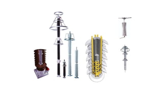
2. Typical components of a power plant substation include busbars, disconnectors, circuit breakers, current transformers, voltage transformers, earthing switches, and surge arrestors.
3. Substations are classified based on their function and location as generating, grid, secondary, distribution, and special purpose substations and based on physical features as indoor, outdoor, pole mounted, and underground substations.
The document describes the key components of a power plant substation or switching station, including busbars, disconnects, circuit breakers, current transformers, voltage transformers, earthing switches, surge arrestors, and overhead ground wires. It provides details on the function of each component and recommended preventative maintenance schedules and tasks for each, such as visual inspections, cleaning, checking connections, and testing grounding systems. Maintenance is recommended at least monthly for some components and at least yearly for others.
The document describes the key components of a power substation or switching station, including:
- Busbars which carry electric current between switches and equipment
- Disconnects which isolate equipment by removing sections of a circuit
- Circuit breakers which interrupt live circuits to disconnect power
- Current and voltage transformers which detect and transform current and voltage for instruments
- Earthing switches which connect equipment to ground for safety during maintenance
- Surge arrestors which provide a path to ground for surges while preventing power currents.
A substation receives high voltage electricity from power plants, steps down the voltage to safer levels for local use, and provides facilities for switching and safety devices. It contains components like busbars to carry electricity, disconnects to isolate equipment, circuit breakers to safely interrupt current, and transformers to detect and transform voltage and current for instruments. Substation equipment requires regular preventative maintenance like cleaning, inspection, and checking for tight connections to ensure safe and reliable operation.
The document provides an overview of a power substation (switchyard) including:
- Typical components including busbars, circuit breakers, current transformers, and surge arrestors.
- Explanations of switchyard equipment such as circuit breakers, isolators, earth switches, and their functions.
- Descriptions of different types of substations based on voltage levels and mounting structures.
- Brief explanations of additional equipment such as capacitive voltage transformers, wave traps, and post insulators.
10 different equipment used in Distribution SubstationDevanshVarma1
A significant factor is the safety and protection of equipment as well as functioning individuals. In addition, as technology advances, different components are regularly upgraded to maintain up with the most delinquent progress to provide consistent Power distribution accessories production.
A substation receives power transmitted at high voltage from a generating station and transforms the voltage to a level appropriate for local use. It consists of transformers, switches, circuit breakers and other equipment to step up or step down voltages. Typical components include busbars to carry current, disconnectors and circuit breakers to connect and disconnect circuits, current and voltage transformers to detect and transform measurements, earthing switches for safety, and surge arrestors to protect from surges. Substations can be classified by their function, such as transformer or industrial substations, or by their control method, such as manual, automatic or supervisory control.
Presentation made at the Nigerian Institution of Electrical & Electronics Engineers (NIEEE) Lagos Chapter. This article gives the reader the basic knowledge of what sub-stations are, how they are designed and the factors considered at the design stage as well as the various protections used at sub-stations.
Switchgear and rectifiers are used to control, protect, and isolate electrical equipment. Switchgear includes disconnect switches, fuses, and circuit breakers, and is used to de-energize equipment for work and clear faults. Rectifiers convert alternating current to direct current through processes like half-wave and full-wave rectification. Common types of switchgear and rectifiers include low voltage switchgear, air circuit breakers, single-phase and three-phase rectifiers, which provide functions like electrical protection, isolation from live parts, and switching. Proper maintenance through inspection, testing, and cleaning helps ensure safe and reliable operation.
The document discusses components and operation of substations, including isolators, busbars, circuit breakers, power transformers, instrument transformers like current and potential transformers, Buchholz relay, earthing methods, and power line carrier communication. It provides details on classifications, principles, and purposes of these various components used in electricity distribution networks.
1. Substations are facilities that link power generation stations to transmission systems and distribution systems by increasing or decreasing voltage levels through transformers.
2. Key components of substations include power transformers, current and potential transformers, circuit breakers, isolators, earth switches, lightning arrestors, and wave traps.
3. Power transformers increase or decrease voltage to allow for efficient transmission of power over long distances and distribution to customers, while current and potential transformers adapt measurements to instrumentation.
Design of a generating substation with the description of designing a transformer. Here we show some basic components of a substation. and we also show the parameters and calculation to design a transformer of a specific ratings.
A switchgear or electrical switchgear is a generic term which includes all the switching devices associated with mainly power system protection. It also includes all devices associated with control, metering and regulating of electrical power system. Assembly of such devices in a logical manner forms a switchgear. This is the very basic definition of switchgear.
⋗To get more with details
https://www.youtube.com/channel/UC2SvKI7eepP241VLoui1D5A
This document provides an introduction to switchgear, including its essential features and components. Switchgear consists of switching and protection devices like circuit breakers, fuses, and relays. It permits switching of electrical equipment under normal operation and detects and isolates faults to protect the system. Key components include switches, fuses, circuit breakers and relays. The document also discusses busbar arrangements, indoor/outdoor accommodation, short circuits and calculating short circuit currents.
The document summarizes the 4 week industrial training that the author completed at NTPC Limited Badarpur Thermal Power Station from June 3rd to July 4th, 2013. The training involved visiting various divisions of the power plant including the Electrical Maintenance Department I (EMD-I), Electrical Maintenance Department II (EMD-II), and Control and Instrumentation Department (C&I). The document then provides details on the basic process of electricity generation from coal, the major components of a power plant, electrical equipment, and laboratories in the Control and Instrumentation Department.
The document is a report summarizing Shuvam Pathania's industrial training at the 220/132/33 KV Grid Sub Station in Jassure. It includes an acknowledgements section thanking those who contributed, a certificate of completion, and a contents listing the topics covered in the report such as the functions of a substation, elements of a substation like circuit breakers and transformers, and an overview of the Jassure Substation.
Ppt on 400 kv gss raiser Bikaner- Yatendra ParasharYatendra Parashar
This document provides an overview of a training presentation on 400kV substations. It discusses:
1) The general components and purpose of substations for transforming voltage from transmission to distribution systems.
2) Details of the 400kV substation including its incoming and outgoing transmission lines carrying voltages of 400kV and 220kV.
3) The key equipment used in substations like power transformers, circuit breakers, instrument transformers, insulators, and isolators.
The present-day electrical power system is A.C. i.e. electric power is generated, transmitted and distributed in the form of alternating current. The electric power is produced at the power stations which are located at favourable places, generally quite away from the consumers. It is delivered to the consumers through a large network of transmission and distribution
Relays are electrically operated switches that use a low-power signal to control a circuit with higher power. They have various operating principles and types. Relays allow for control of circuits with complete isolation and for one signal to control multiple circuits. Common types include latching, induction, reed, mercury-wetted, and solid-state relays. Relays are used where control of high power loads is needed, such as in protection devices, contactors, stabilizers, inverters, and welders. They provide advantages of fast operation, reliability, and allowing control of AC and DC circuits with one device.
The document provides an overview of various electrical components and concepts:
- It defines a fuse as a device that melts under excessive current to interrupt a circuit, and a circuit breaker as an automatically operated switch that can be reset to resume operation after detecting a fault.
- It describes types of circuit breakers (B, C, D) and their applications and tripping characteristics for overcurrent protection.
- It explains that a relay is an electrically operated switch used to control one circuit using a low-power signal from another, isolated circuit, while a contactor is similar but for higher current loads like motors.
- Additional components covered include suppression diodes, wire gauges, current transformers,
The document discusses various types of electrical test equipment used to test circuits and electrical components. It describes multimeters, megohmmeters, low-resistance ohmmeters, hipotential test sets, high current test sets, secondary test sets, relay test sets, power factor test sets, winding resistance test sets, current transformer test sets, ground resistance test sets, and power recorders. The document provides details on what each type of test equipment is used for and how measurements are made.
1. An electric power substation is a facility used to transform electricity from high to low voltage or vice versa for transmission or distribution. It contains equipment like transformers, circuit breakers, and switches.
2. Substations are used to connect generators and transmission lines, transform power between voltage levels, interconnect power sources, switch connections, control voltage and power flow, and detect and respond to faults on the system.
3. They are classified by their main function as transmission substations for high voltages or distribution substations for low voltages. Transformer substations contain transformers while switching substations focus on connections.
This document discusses relays, including their principle of operation, types, advantages, disadvantages, and applications. Relays use an electromagnet to mechanically operate a switch and allow a low-power signal to control a circuit isolated from the control circuit. The main types discussed are latching, induction, reed, mercury-wetted, and solid-state relays. Relays provide benefits like fast operation and reset times but also have disadvantages like requiring maintenance. They are widely used for equipment protection and in applications requiring switching of high power loads.
This document provides an overview of a presentation on practical training at the 400 kV GSS Heerapura substation in Jaipur, India. It defines a grid substation and provides details about the 400 kV GSS Heerapura substation, including its establishment date, capacity, single line diagram, incoming and outgoing feeders. It describes the various components and equipment found at the substation, including transformers, circuit breakers, protective relays, busbars, and also mentions facilities like the transformer repair shop and oil testing lab.
This document provides information about key components of electrical substations. It discusses substations, their purpose of transforming voltage for local use. It describes components like buses that carry current, disconnects that isolate equipment, circuit breakers that interrupt current, current and voltage transformers that detect and transform current and voltage, earthing switches that provide a ground path for safety, and surge arrestors that protect from overvoltage. It provides specifications for common equipment and gives an overview of typical preventative maintenance activities for various substation components.
This document provides details on substation layout and busbar arrangements. Part A discusses substation layout, including a single line diagram and descriptions of common switchyard accessories like lightning arrestors, CVTs, isolators, circuit breakers, transformers, and other equipment. It also covers PLCC and SCADA systems. Part B covers various busbar arrangements like the single bus system, double bus system, one and a half breaker system, and ring main bus system. It discusses the advantages and disadvantages of each configuration. In summary, the document is a technical report that outlines and compares different substation and busbar designs.
Presentation on 132/33KV BSPTCL(Bodhgaya Substation)Rahul Prajapati
The document provides information about the 132/33kV Bodhgaya substation in Bihar, India. It discusses key components of the substation including three transformers ranging from 50-160 MVA, lightning arrestors, current and potential transformers, circuit breakers using oil, air, SF6 and vacuum technologies, isolators, capacitor banks, fuses, and bus couplers connecting generators and feeders to main and spare bus bars. The substation is part of the transmission network operated by Bihar State Power Transmission Company Limited.
This document discusses different methods for collecting primary data, including observation, interviews, questionnaires, and schedules. It provides details on each method such as the steps involved, types or classifications, advantages, and disadvantages. The key methods covered are observation, where a researcher directly observes participants; interviews, which involve asking participants questions; questionnaires, which are forms mailed to participants to complete; and schedules, where an enumerator asks participants questions and records responses, similar to interviews.
This document discusses voltage sag mitigation using a static synchronous compensator (STATCOM). It begins with an introduction to power quality issues such as voltage sags and describes how STATCOM can improve power quality through shunt compensation. Various voltage sag mitigation techniques are reviewed, including ferroresonant transformers, dynamic voltage regulators, static VAR compensators, sag-proofing transformers, static transfer switches, and energy storage options. The document proposes implementing a STATCOM in an induction generator-driven wind farm to mitigate voltage sags caused by load conditions. Diagrams show the load voltage with and without sags, as well as models of the wind farm system both with and without the STATCOM.
Working capital refers to funds used for day-to-day operations of a business. It includes current assets like inventory, receivables, cash, and prepaid expenses. Effective working capital management involves determining the appropriate level of current assets and arranging sources of short-term financing. Key aspects of working capital management include accounts receivable management through techniques like factoring, inventory management using methods such as determining economic order quantity and reorder levels, and evaluating sources of working capital.
The document discusses fundamental analysis for evaluating investment opportunities. It covers analyzing the economy, industries, and individual companies. For economic analysis, it examines factors like GDP, inflation, and interest rates. Industry analysis focuses on growth stage, competition level, and government policies. Company analysis evaluates management, financial statements, earnings forecasts, and financial/non-financial indicators. The goal is to identify sound investments with a reasonable expected return by studying the fundamentals.
This document provides information on technical analysis and its key concepts. It defines technical analysis as using past and current price and volume movements to predict future market direction. It discusses the assumptions of technical analysis and compares it to fundamental analysis. It then describes various charting methods used in technical analysis like bar charts, line charts, point and figure charts, and Japanese candlestick charts. It also covers chart patterns, efficient market theory, Dow theory, and random walk theory as related concepts in technical analysis.
This document defines key concepts related to portfolio management including portfolio, portfolio analysis, construction, and evaluation. A portfolio is a combination of different financial securities like stocks, bonds, and cash held by investors. Portfolio management involves identifying objectives, developing strategies, monitoring performance, and evaluating results. Portfolio analysis assesses the risks of an entity's business areas. Construction requires determining objectives and formulating investment strategies. Evaluation models like Sharpe ratio, Treynor ratio, and Jensen measure are used to assess risk-adjusted performance.
The document discusses capital budgeting, which refers to the planning process used to determine whether long-term investments are worth funding with cash. It defines capital budgeting, outlines its key characteristics and process, and describes various techniques used, including payback period, accounting rate of return, net present value, internal rate of return, and profitability index. It also discusses determining relevant cash flows, the cost of capital, and calculating the weighted average cost of capital.
Working capital refers to the capital required to meet the day-to-day operational expenses of a business like wages, raw materials, utilities etc. It consists of current assets like inventory, receivables, cash etc. Proper management of working capital involves determining the optimal level of current assets and liabilities and arranging sources to finance them. The key components of working capital to be managed are inventory, receivables and cash. Firms use various short-term financing options like bank finance, trade credit, commercial paper etc. to manage their working capital requirements.
The document discusses various concepts related to leverage, dividends, and dividend policy. It defines leverage as using assets and funds with fixed costs to increase shareholder returns. It also defines different types of leverage including operating, financial, and combined leverage and provides formulas to calculate them. The document also defines dividends and lists various sources and forms of dividends. Finally, it discusses dividend policy, factors affecting policy, and theories related to dividends proposed by Modigliani-Miller, Walter, and Gordon.
The document provides information on various aspects of the Indian capital market, including definitions of key terms like capital market, primary market, secondary market, and sources of long-term financing. It also discusses various capital market instruments like shares, debentures, term loans, leasing, hire purchase, venture capital, and private equity - outlining their meaning, types, advantages and disadvantages. The primary and secondary segments of the Indian capital market are described along with new issue market and stock market.
The document discusses key concepts in investment analysis including:
1) The various steps involved in the investment process such as setting objectives, establishing policy, selecting strategies and assets, and measuring performance.
2) Definitions of return, risk, systematic and unsystematic risk, beta which measures sensitivity to market returns, and alpha which measures performance independent of market returns.
3) The meanings of speculation which involves taking business risks for short term gains, and gambling which involves wagering without understanding the risks.
The document presents a STATCOM control scheme for improving power quality in a grid-connected wind energy generation system. A battery energy storage system is integrated with the STATCOM to help stabilize the grid during fluctuations in wind power. The control scheme is simulated in MATLAB/Simulink. Results show the STATCOM is able to maintain unity power factor at the point of common coupling, reducing harmonics to below 0.01% and frequency oscillations to less than 1%. This allows the system to meet power quality standards while supporting the wind generator and loads on the grid.
This document discusses different types of substation bus schemes, including single bus, double bus with double or single breakers, main and transfer bus, ring bus, breaker-and-a-half with two main buses, and double bus-bar with bypass isolators. The choice of bus scheme depends on factors like safety, reliability, voltage level, simplicity of relaying, flexibility of operation, cost, maintenance needs, available land, and the location and provision of connecting lines and expansion. Seven common bus scheme types are described but not explained in detail.
1) Sub-stations are facilities that change characteristics of electric power such as voltage, frequency, and power factor. They receive power at one voltage and deliver it at another.
2) Sub-stations are classified based on their function (e.g. transformer, switching) and construction (e.g. indoor, outdoor). Transformer sub-stations change voltage levels while switching sub-stations perform switching without changing voltage.
3) Key equipment in sub-stations include transformers, circuit breakers, buses, insulators, and instrumentation transformers which step voltages/currents down for metering and protection. Proper layout and equipment are needed for safe and reliable power distribution.
1) Sub-stations are facilities that change characteristics of electric power supply like voltage, frequency, and current. They receive power at one voltage and deliver at another.
2) Sub-stations are classified by their service (e.g. transformer, switching) and construction (e.g. indoor, outdoor). Transformer sub-stations are the most common and change the voltage level.
3) Key equipment in sub-stations includes transformers, busbars, insulators, circuit breakers, and protection devices that allow safe transmission of power from high voltage lines to distribution networks.
The document provides information about transmission and distribution of electric power. It discusses key topics like:
- The historical development of AC and DC transmission systems.
- The basic structure of an electric power system including generation, transmission, and distribution.
- Different types of transmission lines like overhead lines and underground cables, and their characteristics.
- Components of transmission and distribution systems like towers, conductors, transformers and substations.
- High voltage direct current transmission including different technologies and applications.
- Mechanical design aspects of transmission lines including line supports, sag and tension calculations, and effects of wind and ice loading.
The document presents a wind-solar hybrid power generation system that aims to harness both wind and solar power, store the generated power in batteries, and design a charger for the batteries. The major advantage of the hybrid system is its enhanced reliability from combining solar and wind sources. It has low operating costs and high power quality. The block diagram shows the system design and it has applications for powering cell towers, rural areas, homes, and street lighting.
This document describes the design of a micro solar inverter. It begins with an abstract that outlines how the micro inverter converts DC power from a solar panel to AC power and is mounted directly behind the panel for simplified installation. It then provides details on solar power generation, characteristics of solar panels, and compares centralized string inverters to the proposed micro inverter system. The document concludes that micro inverters have been successful for residential use where space is limited, as they can produce AC power directly at the back of each panel.
Perception is how individuals interpret and organize their sensory impressions to make sense of their environment, but what we perceive can differ from objective reality. Managers need to understand how perception affects various aspects of managing employees. Perception influences motivation, as employees who are experiencing money troubles may perceive compensation issues differently. It also impacts hiring, as contrasts between job applicants can affect hiring decisions based on perceptions. Performance appraisals are highly dependent on the accuracy of a manager's perceptions of a subordinate's work.
This presentation includes basic of PCOS their pathology and treatment and also Ayurveda correlation of PCOS and Ayurvedic line of treatment mentioned in classics.
A review of the growth of the Israel Genealogy Research Association Database Collection for the last 12 months. Our collection is now passed the 3 million mark and still growing. See which archives have contributed the most. See the different types of records we have, and which years have had records added. You can also see what we have for the future.
Exploiting Artificial Intelligence for Empowering Researchers and Faculty, In...Dr. Vinod Kumar Kanvaria
Exploiting Artificial Intelligence for Empowering Researchers and Faculty,
International FDP on Fundamentals of Research in Social Sciences
at Integral University, Lucknow, 06.06.2024
By Dr. Vinod Kumar Kanvaria
ISO/IEC 27001, ISO/IEC 42001, and GDPR: Best Practices for Implementation and...PECB
Denis is a dynamic and results-driven Chief Information Officer (CIO) with a distinguished career spanning information systems analysis and technical project management. With a proven track record of spearheading the design and delivery of cutting-edge Information Management solutions, he has consistently elevated business operations, streamlined reporting functions, and maximized process efficiency.
Certified as an ISO/IEC 27001: Information Security Management Systems (ISMS) Lead Implementer, Data Protection Officer, and Cyber Risks Analyst, Denis brings a heightened focus on data security, privacy, and cyber resilience to every endeavor.
His expertise extends across a diverse spectrum of reporting, database, and web development applications, underpinned by an exceptional grasp of data storage and virtualization technologies. His proficiency in application testing, database administration, and data cleansing ensures seamless execution of complex projects.
What sets Denis apart is his comprehensive understanding of Business and Systems Analysis technologies, honed through involvement in all phases of the Software Development Lifecycle (SDLC). From meticulous requirements gathering to precise analysis, innovative design, rigorous development, thorough testing, and successful implementation, he has consistently delivered exceptional results.
Throughout his career, he has taken on multifaceted roles, from leading technical project management teams to owning solutions that drive operational excellence. His conscientious and proactive approach is unwavering, whether he is working independently or collaboratively within a team. His ability to connect with colleagues on a personal level underscores his commitment to fostering a harmonious and productive workplace environment.
Date: May 29, 2024
Tags: Information Security, ISO/IEC 27001, ISO/IEC 42001, Artificial Intelligence, GDPR
-------------------------------------------------------------------------------
Find out more about ISO training and certification services
Training: ISO/IEC 27001 Information Security Management System - EN | PECB
ISO/IEC 42001 Artificial Intelligence Management System - EN | PECB
General Data Protection Regulation (GDPR) - Training Courses - EN | PECB
Webinars: https://pecb.com/webinars
Article: https://pecb.com/article
-------------------------------------------------------------------------------
For more information about PECB:
Website: https://pecb.com/
LinkedIn: https://www.linkedin.com/company/pecb/
Facebook: https://www.facebook.com/PECBInternational/
Slideshare: http://www.slideshare.net/PECBCERTIFICATION
Main Java[All of the Base Concepts}.docxadhitya5119
This is part 1 of my Java Learning Journey. This Contains Custom methods, classes, constructors, packages, multithreading , try- catch block, finally block and more.
The simplified electron and muon model, Oscillating Spacetime: The Foundation...RitikBhardwaj56
Discover the Simplified Electron and Muon Model: A New Wave-Based Approach to Understanding Particles delves into a groundbreaking theory that presents electrons and muons as rotating soliton waves within oscillating spacetime. Geared towards students, researchers, and science buffs, this book breaks down complex ideas into simple explanations. It covers topics such as electron waves, temporal dynamics, and the implications of this model on particle physics. With clear illustrations and easy-to-follow explanations, readers will gain a new outlook on the universe's fundamental nature.
2. SUBSTATION
SUBSTATION - A station in the power transmission system at which electric power is
transformed to a conveniently used form. The station may consist of transformers,
switches, circuit breakers and other auxiliary equipment. Its main function is to receive
energy transmitted at high voltage from the generating station, by either step-up or step-
down the voltage to a value appropriate for local use and provide facilities for
switching. Substations have some additional functions. Its provide points where safety
devices may be installed to disconnect circuits or equipment in the event of trouble.
4. BUSBAR
BUSBAR (or bus, for short) – is a term we use for a main bar or conductor carrying
an electric current to which many connection may be made.
Buses are merely convenient means of connecting switches and other
equipment into various arrangements. The usual arrangement of connections in
most substations permit working on almost any piece of equipment without
interruption to incoming or outgoing feeders. In the switchyard or substation,
buses are open to the air. Aluminum or copper conductors supported on porcelain
insulators, carry the electric energy from point to point.
6. DISCONNECTS
DISCONNECT – is an easily removed piece of the actual conductor of a circuit. The
purpose of disconnects is to isolate equipment. Disconnects are not used to interrupt
circuits; they are no-load devices. A typical use of disconnects is to isolate a circuit
breaker by installing one disconnect on either side of the circuit breaker (in series with
the breaker). Operation of disconnects is one of the most important and responsible jobs
of a power plant operator. One error in isolation of equipment, or the accidental
grounding of line equipment, can be a fatal mistake.
8. CIRCUIT BREAKER
CIRCUIT BREAKER – is used to interrupt circuits while current is flowing through them.
The making and breaking of contacts in a Oil type circuit breaker are done under oil, this oil
serves to quench the arc when the circuit is opened. The operation of the breaker is very
rapid when opening. As with the transformer, the high voltage connections are made
through bushings. Circuit breakers of this type are usually arranged for remote electrical
control from a suitably located switchboard.
Some recently developed circuit breakers have no oil, but put out the arc by a blast
of compressed air; these are called air circuit breakers. Another type encloses the contacts
in a vacuum or a gas (sulfur hexafluoride, SF6) which tends to self maintain the arc.
10. CURRENT TRANSFORMER
CURRENT TRANSFORMER – Current transformer are used with
ammeters, watt meters, power-factor meters, watt-hour
meters,compensators, protective and regulating relays and the trip coil of
circuit breakers. One current transformer can be used to operate several
instruments, provided that the combined burden does not exceed that for
which the transformer is designed and compensated. The current
transformer is connected directly in series with the line.
11.
12. VOLTAGE TRANSFORMER
VOLTAGE TRANSFORMER – also know as potential transformer, are used with
volt-meters, wattmeters, watt-hour meters, power-factor meters, frequency meters,
synchroscopes and synchronizing apparatus, protective and regulating relays and the
no-voltage and over-voltage trip coils of automatic circuit breakers. One transformer
can be used for a number of instruments at the same time if the total current taken by
the instrument does not exceed that for which the transformer is designed and
compensated. The ordinary voltage transformer is connected across the line, and the
magnetic flux in the core depends upon the primary voltage
13.
14. EARTHING SWITCH
EARTHING SWITCH – also known as ground disconnect, which used to connects
the equipment to a grid of electrical conductors buried in the earth on the station
property. It is intended to protect people working on the grounded equipment. It does
this by completing a circuit path, thereby reducing the voltage difference between the
equipment and its surroundings. For safety reasons, it is important that ground
disconnects and all associated connections have good contact and low resistance. It is
also important that the protective ground not be accidentally remove, that is why all
the earthing switches, disconnect switches and circuit breakers are all interlocked to
each other and proper/correct sequencing must be followed.
15. SURGE ARRESTOR
SURGE ARRESTOR – are devices used to provide the necessary path to ground for such surges,
yet prevent any power current from following the surge. An ideal arrester must therefore have the
following properties:
1. Ability to remove the surge energy from the line in a min. time.
2. High resistive to flow of power current.
3. A valve action automatically allowing surge to pass and then closing up so as not to
permit power current to flow to ground.
4. Always ready to perform.
5. Performance such that no system disturbances are introduced by its operation.
6. Economically feasible
16.
17. • OVERHEAD GROUND WIRE – by a ground wire is meant a wire, generally
of steel, supported from the top of transmission-line towers and solidly grounded
at each tower. It is considered a preventive device, but it does not entirely prevent
the formation of travelling waves on a line. Furthermore, those lines which are
not equipped with ground wires will be subjected to disturbances which produce
surges that must be allowed to escaped to ground, or the apparatus connected to
the line must be strong enough to reflect or absorb these surges until they are
entirely damped out.
18.
19. PREVENTIVE MAINTENANCE
BUSBARS & OVERHEAD GROUND WIRE
At least once a year
• Visual Inspection & Examination of all wiring connectors.
• Check Insulator , clean or apply HVIC if necessary.
• Check the physical condition of bus (cables or bars)
• For ground wire, check or test the grounding system.
DISCONNECT & EARTHING SWITCHES
At least once a month
• Visual Inspection.
• Check heating resistor located at its control panel for proper functioning.
At least once a year
• Clean contacts of disconnectors as well as earthing switches and apply
electrical contact grease , if necessary.
20. • Check disconnectors and earthing switches, joints and
bearings of the operating linkages for deformed bearing
points.
• Check flexible connections of earthing switches.
• Check all screwed joints for tight fit.
• Clean insulators if necessary, when an excessive amount of
dirt has accumulated.
• Carry-out the maintenance of operating mechanism.
21. VOLTAGE TRANSFORMER
At least once a month
• Inspect the voltage divider to be sure that no oil leak or serious
accumulation of soot, dust or salt composite is present.
• Inspect the intermediate voltage transformer and check the
minimum permissible oil level.
At least once a year
• Check all screwed joints & contact for tight fit.
• Clean insulators if necessary, when an excessive amount of dirt
has accumulated.
22. CURRENT TRANSFORMER
At least once a month
• Visual Inspection to check oil level and defects or possible
oil leaks.
At least once a year
• Check all screwed joints & contact for tight fit.
• Clean insulators if necessary, when an excessive amount of
dirt has accumulated.
• Check primary and secondary connectors and conduct
necessary tightening.
Note: Never open a secondary winding of a CT while on
service.
23. SURGE ARRESTOR
At least once a year
• Visual Inspection & Examination of all wiring connectors.
• Check Insulator and metal circular ring, clean or apply HVIC if necessary.
• Check the physical condition of bus (cables or bars) For ground wire, check or
test the grounding system.
• Note: Arrestors should never be touched unless completely disconnected from
all live lines and equipment and effectively connected to ground at the line
side of the arrestor.
25. FEEDERS
• These are the cables supplying power in bulk to a selected number of points called
feeding points The feeders run along streets overhead (or underground, in some cases)
and power the distribution transformers at or near the customer premises.
25
26. DISTRIBUTORS
• Distributors are used for current Tapping for the various consumers these
cables are generally having the main street for there route .
26
27. SERVICE MAIN
• Service mains are the small cables teed of off from the distributors and taken into the
premises of the various consumers these are low tension cables.
27
28. TYPES OF NEUTRAL GROUNDING
Solid grounding
Resistance grounding
Reactance grounding
Are suppression coil or Peterson coil or resonant grounding
Voltage transformer grounding
Zig-zag transformer grounding.
29. Solid grounding:
In solid grounding a direct metallic connection is made as shown in the following
figure. From the system neutral one or more earth electrodes consisting of pipes,
plates or rods are buried in the ground.
When an earth fault occurs between earth and any one phase, the voltage to
earth of the faulty phase becomes zero, but the healthy phase, remains at their
normal phase values.
So lightning arresters of low voltage rating can be used, saving the cost
30. The flow of heavy current If completely nullifies the effect of the
capacitive current Ic at the fault and so no arcing ground or over voltages.
Due to the flow of high fault current, protective relaying is possible.
Increase in earth fault current causes disturbance in the neighboring
communication lines.
Heavy fault current may damage the circuit breaker contacts.
Use of solid grounding is limited to only to system where the normal
circuit impedance is sufficient to prevent very high fault current.
31. Types of substations
As an integral part of the transmission system, the substation as switching station
functions as a connection and switching point for transmission lines. Sub-
transmission feeders, generating circuits and step up and step down transformers.
The objective of substation is to provide maximum reliability, flexibility and
continuity of service and minimise investment cost and safety system requirements.
32. Depending on the service purpose, the substation may be classified
as follows
Generating substations or step-up substation:-
Generating substations are located near the generating plants. The generating
voltages are 11kv,10kv, 6.6kv or 13.8kv respectively, and need to be stepped upto
the transmission voltages in the range of 66of or 110kv or 132kv or 220kv. So that
large amount of power can be transmitted economically over long distance. Each
generating unit is connected to generating transformers to increase the secondary
voltage upto transmission voltage level.
Grid substations:-
Grid substations are located in the intermediate points between the generating
stations and load centres. Load centre receive all the information from the
generating stations and to ensure corrective actions. The main purpose of these
substations is to provide connections of low voltage lines, some compensating
devices etc.
33. Secondary substations:-
These substations are connected with the main grid substations with the help of
secondary transmission lines. The voltages at these substations are stepped down to the
primary distribution voltage or sub-transmission voltage such as 11kv or 6.6kv directly
connected to these substations.
Distribution substation:-
Distribution substations are connected between primary distribution and secondary
distribution. The primary distribution voltage such as 11kv or 6.6kv is to be stepped
down to the supply voltage (400v for three phase and 230v for single phase). These
substations transfer power to the consumers through distributors and service main.
34. Special purpose substations:-
a) Traction substation and mining substation:
These substations transfer bulk power. Special design considerations are required in these
substations such as load distribution in phases in traction substation and safety precautions in the
mining substations.
b)Power factor correction substations:-
These substations are used to improve power factor of the system. These are located at the
receiving end of transmission lines. We use synchronous contenders as the power factor
improvement equipment.
35. c) Frequency changer substations:-
These substations are used to change the supply frequency. Such a frequency change
may be used for some industrial utilisation.
d) Converting substations:-
The converting substations are used to convert a.c power into d.c power. These
substations are required for some purpose like traction, electroplating, electric
welding etc
e) Mobile substations:-
These are used for construction purpose, which are temporary as mobile.
36. Depending upon the physical features, the substation can be classified as follows:
Indoor substations
These secondary substations are of indoor type. The equipment of indoor substations lie
in a room because of economic consideration. The operating voltage are normally 11kv.
These substations are located in big cities.
Outdoor substations:-
The distribution stations are mostly of outdoor type. All equipments required for
switches,circuit breakers, lightning arrestors, potential transformer, current transformers,
capacitor banks are installed outdoor (i.e., open in the air) . Normally, these substations
are used for 33kv voltage and above for cost and safety reasons. The air clearances
required are large. The control and monitoring are performed inside the control rooms.
37. Pole mounted or open or kiosk type:-
These substations are mounted on H-pole (upto 160 KVA) or an iron platform formed by
4-pole structure (upto 400KVA) . These substations are simple and cheap. These are not
required any building for housing the equipments. The operating voltages are upto 11kv.
Electric power is distributed to the consumer from these substations.
Underground substations:-
In highly populated areas, the land required for building equipments is limited and also
the cost of land is very high. Underground substation is located underground. The size of
the substation depends upon the capacity.