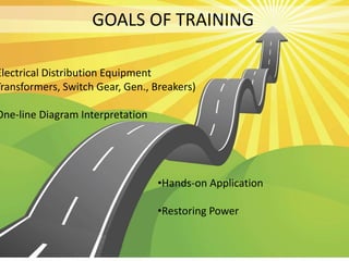
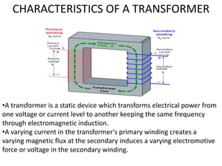
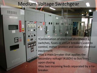
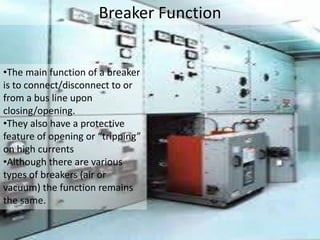
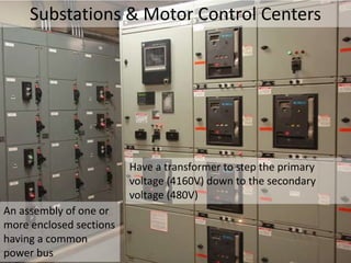
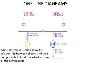
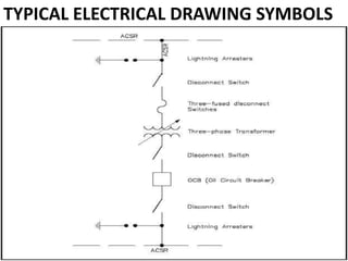
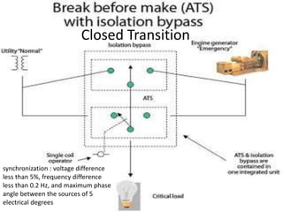
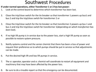
SlideShare a Scribd company logo
POWER DISTRIBUTION
TRAINING
GOALS OF TRAINING
Electrical Distribution Equipment
Transformers, Switch Gear, Gen., Breakers)
One-line Diagram Interpretation
•Hands-on Application
•Restoring Power
What is a Transformer?
NO YES
CHARACTERISTICS OF A TRANSFORMER
•A transformer is a static device which transforms electrical power from
one voltage or current level to another keeping the same frequency
through electromagnetic induction.
•A varying current in the transformer's primary winding creates a
varying magnetic flux at the secondary induces a varying electromotive
force or voltage in the secondary winding.
High Voltage Transformers Characteristics
•Steps primary voltage (28KV) down on the secondary voltage (4160V)
•Oil inside of these transformers acts as a cooling agent to reduce heat
•Nitrogen is applied to transformers to remove oxygen and water
Medium Voltage Switchgear
•Combination of electrical disconnect
switches, fuses or circuit breakers used to
control, meter, protect and isolate electrical
equipment
•Has a main breaker that applies the
secondary voltage (4160V) to bus lines
upon closing
•Has two incoming feeds separated by a tie-
breaker.
Breaker Function
•The main function of a breaker
is to connect/disconnect to or
from a bus line upon
closing/opening.
•They also have a protective
feature of opening or “tripping”
on high currents
•Although there are various
types of breakers (air or
vacuum) the function remains
the same.
Substations & Motor Control Centers
Have a transformer to step the primary
voltage (4160V) down to the secondary
voltage (480V)
An assembly of one or
more enclosed sections
having a common
power bus
Emergency Generators
•Diesel powered systems that generate their own power to be applied
to switchgear automatically in the event of full power loss
•Have a peak shaving component that aids in power consumption
reduction
ONE-LINE DIAGRAMS
A line diagram is used to show the
relationship between circuits and their
components but not the actual location
of the components
TYPICAL ELECTRICAL DRAWING SYMBOLS
Simple One-Line Diagram
Schematic
Loss of Power Scenarios
Scenario: A plant with 2 transformers has the
motor load evenly distributed. No bus ties are
closed.
There is a loss of power on transformer 1. What
happens?
There is a power loss on 1 and 2
transformers. What happens?
The breaker feeding one side of
the substation fails open. What
happens?
Controlled Shutdown
In the event of an scheduled shutdown of one or
more primary transformers, what are some of
the procedures that need to be followed?
1. First unload affected
switchgear bus by
removing pumps from
service and tying
substation feeds to
provide for
uninterrupted service as
needed.
3. Remove control fuses
2. Open main
breaker from
control panel
remote switch
Remove control
fuses
4. For further
isolation breaker
may be lowered
and removed from
cabinet.
BREAKERS
A circuit breaker is an automatically operated electrical switch designed
to protect an electrical circuit from damage caused by overload or short
circuit. Its basic function is to detect a fault condition and interrupt
current flow.
The circuit breaker which operates in air at atmospheric pressure. For
interrupting arc it creates an arc voltage in excess of the supply voltage.
Vacuum Circuit Breakers
These breakers interrupt the current
by creating and extinguishing the arc
in a vacuum container - aka "bottle".
Long life bellows are designed to
travel the 6-10 mm the contacts must
part. Vacuum circuit breakers tend to
have longer life expectancies between
overhaul than do air circuit breakers
Oil Circuit Breakers
The oil is used to insulate between the phases and between the phases
and the ground, and to extinguish the arc. When electric arc is drawn
under oil, the arc vaporizes the oil and creates a large bubble of
hydrogen that surrounds the arc. The oil surrounding the bubble
conducts the heat away from the arc and thus also contributes to
deionization and extinction of the arc.
Purpose of Main/Tie Breakers/Interlocks
The tie breaker system is designed only to have one transformer
operating when the tie breakers are closed, or in other words the
system is not intended to run with the utility transformer paralleled.
Interlock systems are in place to ensure that the ties and both mains are
never all closed at once putting transformers in parallel.
Typical Tie-Breaker with
Interlocks
Difference Between Breakers for Medium
Voltage and Substations
Substations transform voltage from
high to low, typically 4160V to 480V,
and operate under the same
governing principles as medium
voltage switchgear.
Switchgear is the combination
of electrical disconnect
switches, fuses or circuit
breakers used to control,
protect and isolate electrical
equipment loads of 4160V
Open Transition Breaker
It prevents back feeding from an
emergency generator back into
the utility line
Closed Transition
synchronization : voltage difference
less than 5%, frequency difference
less than 0.2 Hz, and maximum phase
angle between the sources of 5
electrical degrees
Raking in and out of Breakers
Racking provides a method of
isolating a high-voltage
metal-clad circuit breaker
from its supply and load
circuits, and/or to provide
grounding. Before racking,
the circuit breaker must be
opened, and this is usually
ensured using an interlock
system.
RESTORING POWER
1. Knowledge of Procedure
2. Response Time
3. Contacting Effected
Parties
4. Investigating the Cause
5. Waiting for Stability
Restoring Power Scenarios
There is a loss of power on
transformer 1. How do you restore
power?
There is a power loss on 1 and 2
transformers. How do you
restore power?
The breaker feeding one side of
substation 1 fails open. How
do you restore power?
Southwest Procedures
If under normal operations, either Transformer 1 or 2 has lost power:
1. Look at the control board to determine which transformer has been lost.
2. Close the trip/close switch for the tie breaker so that transformer 1 powers up bus1 and
bus 2 and trip the trip/close switch for transformer 2 or
3. Close the trip/close switch for the tie breaker so that transformer 2 powers up bus 1 and
bus 2 and trip the trip/close switch for transformer 1(depending on which transformer has
been lost).
4. If no high lift pump is in service due to the power loss, start a high lift pump as soon as
possible to restore system pressure.
5. Notify systems control and the senior chemist that there has been a loss of power and
request their preference as to which pumps should be put in service so that adjustments
can be made.
6. Put the desired high lift and low lift pumps in service.
7. The sr. operator, operator and sr. chemist will coordinate to restart all equipment and
machinery that may have been affected by the power loss.
8. Be sure to do a trouble report so that the emergency can be documented.
Response Time
It is critical to react safely, competently
and quickly to power loss events. Being
aware of what power source is
supplying equipment in service, and
relying on your team (Water Techs,
Chemist, SCC) to provide information in
cause of an loss is essential.
If possible, starting another pump to
restore system pressure is the priority
over restoring loss power.
Contacting DTE/SCC/Management
Notification of power loss and the current
status is crucial during a power loss event.
Contact numbers for SCC and DTE should be
posted or readily available.
Notification of management and detailed
documentation of what occurred and the steps
taken to restore power are also important.
Troubleshooting Power Loss
After restoring system
pressure and establishing a
power source, the next step is
to investigate the potential
causes of the power loss.
Although you are not an electrician, detailed notes of what has taken
place during the event are necessary for the maintenance crew to find
the cause and repair or replace any damaged equipment.
Following Proper Procedures/Waiting for
Stability
Before normal power
distribution operation
can be restored, a high
probability of stability
must be known.
Helps to avoid a repeat
of the power loss.
Working with DTE or
the maintenance crew
to establish cause will
provide insight
You are the first line of
defense in protecting
the public.
Test Time

More Related Content

What's hot

Types Of Substations
Types Of SubstationsTypes Of Substations
Types Of Substationssapna186
 
TDU Unit 03 Distribution Systems
TDU Unit  03 Distribution SystemsTDU Unit  03 Distribution Systems
TDU Unit 03 Distribution SystemsPremanandDesai
 
Electrical distribution system
Electrical distribution system Electrical distribution system
Electrical distribution system Ankush Bharti
 
Electricity distribution system in india
Electricity distribution system in indiaElectricity distribution system in india
Electricity distribution system in indiaJasgt Singh
 
Substations
SubstationsSubstations
Substationsitfakash
 
Design of substation (with Transformer Design)
Design of substation (with Transformer Design) Design of substation (with Transformer Design)
Design of substation (with Transformer Design) SayanSarkar55
 
Protection Devices and the Lightning
Protection Devices and the LightningProtection Devices and the Lightning
Protection Devices and the LightningAmeen San
 
Electrical 132kv substation project .. shakir
Electrical 132kv substation project .. shakirElectrical 132kv substation project .. shakir
Electrical 132kv substation project .. shakirSheikh Shakir
 
Electric substation
Electric substation Electric substation
Electric substation ANNU KUMAR
 
Various Bus-Bar Arrangements.
Various Bus-Bar Arrangements.Various Bus-Bar Arrangements.
Various Bus-Bar Arrangements.SaiSampath16
 
Substation protection devices
Substation protection devicesSubstation protection devices
Substation protection devicesRahul Aman
 
Electrical grounding and earthing systems
Electrical grounding and earthing systemsElectrical grounding and earthing systems
Electrical grounding and earthing systemsBiswajit Pratihari
 
Overhead line work ppt
Overhead line work pptOverhead line work ppt
Overhead line work pptDemsew Mitiku
 

What's hot (20)

Types Of Substations
Types Of SubstationsTypes Of Substations
Types Of Substations
 
TDU Unit 03 Distribution Systems
TDU Unit  03 Distribution SystemsTDU Unit  03 Distribution Systems
TDU Unit 03 Distribution Systems
 
Electrical distribution system
Electrical distribution system Electrical distribution system
Electrical distribution system
 
Substation
Substation Substation
Substation
 
Electricity distribution system in india
Electricity distribution system in indiaElectricity distribution system in india
Electricity distribution system in india
 
Substations
SubstationsSubstations
Substations
 
Protection and Switchgear
Protection and SwitchgearProtection and Switchgear
Protection and Switchgear
 
Distribution System
Distribution SystemDistribution System
Distribution System
 
Ac distribution
Ac distributionAc distribution
Ac distribution
 
Electrical Installations
Electrical InstallationsElectrical Installations
Electrical Installations
 
Transmission and Distribution of Electric Power system
Transmission and Distribution of Electric Power systemTransmission and Distribution of Electric Power system
Transmission and Distribution of Electric Power system
 
Design of substation (with Transformer Design)
Design of substation (with Transformer Design) Design of substation (with Transformer Design)
Design of substation (with Transformer Design)
 
Protection Devices and the Lightning
Protection Devices and the LightningProtection Devices and the Lightning
Protection Devices and the Lightning
 
Electrical 132kv substation project .. shakir
Electrical 132kv substation project .. shakirElectrical 132kv substation project .. shakir
Electrical 132kv substation project .. shakir
 
Electric substation
Electric substation Electric substation
Electric substation
 
Various Bus-Bar Arrangements.
Various Bus-Bar Arrangements.Various Bus-Bar Arrangements.
Various Bus-Bar Arrangements.
 
Substation protection devices
Substation protection devicesSubstation protection devices
Substation protection devices
 
Electrical grounding and earthing systems
Electrical grounding and earthing systemsElectrical grounding and earthing systems
Electrical grounding and earthing systems
 
Overhead line work ppt
Overhead line work pptOverhead line work ppt
Overhead line work ppt
 
IEEE substation design
IEEE substation designIEEE substation design
IEEE substation design
 

Viewers also liked

Switchgear and Distribution Systems
Switchgear and Distribution SystemsSwitchgear and Distribution Systems
Switchgear and Distribution SystemsLiving Online
 
Electrical Systems in a Building
Electrical Systems in a BuildingElectrical Systems in a Building
Electrical Systems in a BuildingGAURAV. H .TANDON
 
Summer Internship Report -By Rahul Mehra
Summer Internship Report -By Rahul MehraSummer Internship Report -By Rahul Mehra
Summer Internship Report -By Rahul MehraRahul Mehra
 
Switch gear & control gear industry in india
Switch gear & control gear industry in indiaSwitch gear & control gear industry in india
Switch gear & control gear industry in indiaValueNotes
 
electrical distribution system ppt/13b61a0221
electrical distribution system ppt/13b61a0221electrical distribution system ppt/13b61a0221
electrical distribution system ppt/13b61a0221saikrishna kandhikatla
 
POWER SYSTEM PROTECTION
POWER SYSTEM PROTECTION POWER SYSTEM PROTECTION
POWER SYSTEM PROTECTION moiz89
 
Building Services Engg. (Electrical installations)
Building Services Engg. (Electrical installations)Building Services Engg. (Electrical installations)
Building Services Engg. (Electrical installations)Ritesh Ambadkar
 
HIGH VOLTAGE ENGINEERING
HIGH VOLTAGE ENGINEERINGHIGH VOLTAGE ENGINEERING
HIGH VOLTAGE ENGINEERINGrpsswitchgear
 
Unit commitment in power system
Unit commitment in power systemUnit commitment in power system
Unit commitment in power systemAbrar Ahmed
 
Measurement of high_voltage_and_high_currentunit_iv_full_version
Measurement of high_voltage_and_high_currentunit_iv_full_versionMeasurement of high_voltage_and_high_currentunit_iv_full_version
Measurement of high_voltage_and_high_currentunit_iv_full_versionAman Ansari
 
MedPower2016_S4_Paper003_SinisaSpremicPresentation
MedPower2016_S4_Paper003_SinisaSpremicPresentationMedPower2016_S4_Paper003_SinisaSpremicPresentation
MedPower2016_S4_Paper003_SinisaSpremicPresentationSinisa Spremic
 
2.4 গতি সংক্রান্ত বিভিন্ন রাশি(ssc physics bangla)
2.4 গতি সংক্রান্ত বিভিন্ন রাশি(ssc physics bangla)2.4 গতি সংক্রান্ত বিভিন্ন রাশি(ssc physics bangla)
2.4 গতি সংক্রান্ত বিভিন্ন রাশি(ssc physics bangla)Sifat E Mohammad
 
Ranciels Power Supply System Presentation
Ranciels Power Supply System PresentationRanciels Power Supply System Presentation
Ranciels Power Supply System Presentationrancil1
 
Smart transformer and Analog transformer.
Smart transformer and Analog transformer.Smart transformer and Analog transformer.
Smart transformer and Analog transformer.Hossain Al Kayum
 
জীববিজ্ঞান শর্ট টেকনিক
জীববিজ্ঞান শর্ট টেকনিকজীববিজ্ঞান শর্ট টেকনিক
জীববিজ্ঞান শর্ট টেকনিকMohammad Mizanur Rahaman Onik
 

Viewers also liked (19)

Switchgear and Distribution Systems
Switchgear and Distribution SystemsSwitchgear and Distribution Systems
Switchgear and Distribution Systems
 
Electrical Systems in a Building
Electrical Systems in a BuildingElectrical Systems in a Building
Electrical Systems in a Building
 
Summer Internship Report -By Rahul Mehra
Summer Internship Report -By Rahul MehraSummer Internship Report -By Rahul Mehra
Summer Internship Report -By Rahul Mehra
 
Switch gear & control gear industry in india
Switch gear & control gear industry in indiaSwitch gear & control gear industry in india
Switch gear & control gear industry in india
 
electrical distribution system ppt/13b61a0221
electrical distribution system ppt/13b61a0221electrical distribution system ppt/13b61a0221
electrical distribution system ppt/13b61a0221
 
POWER SYSTEM PROTECTION
POWER SYSTEM PROTECTION POWER SYSTEM PROTECTION
POWER SYSTEM PROTECTION
 
Building Services Engg. (Electrical installations)
Building Services Engg. (Electrical installations)Building Services Engg. (Electrical installations)
Building Services Engg. (Electrical installations)
 
HIGH VOLTAGE ENGINEERING
HIGH VOLTAGE ENGINEERINGHIGH VOLTAGE ENGINEERING
HIGH VOLTAGE ENGINEERING
 
Unit commitment in power system
Unit commitment in power systemUnit commitment in power system
Unit commitment in power system
 
Measurement of high_voltage_and_high_currentunit_iv_full_version
Measurement of high_voltage_and_high_currentunit_iv_full_versionMeasurement of high_voltage_and_high_currentunit_iv_full_version
Measurement of high_voltage_and_high_currentunit_iv_full_version
 
MedPower2016_S4_Paper003_SinisaSpremicPresentation
MedPower2016_S4_Paper003_SinisaSpremicPresentationMedPower2016_S4_Paper003_SinisaSpremicPresentation
MedPower2016_S4_Paper003_SinisaSpremicPresentation
 
Physics2ndpaper
Physics2ndpaperPhysics2ndpaper
Physics2ndpaper
 
C Tutorial Bangla Introduction 00
C Tutorial Bangla Introduction 00C Tutorial Bangla Introduction 00
C Tutorial Bangla Introduction 00
 
2.4 গতি সংক্রান্ত বিভিন্ন রাশি(ssc physics bangla)
2.4 গতি সংক্রান্ত বিভিন্ন রাশি(ssc physics bangla)2.4 গতি সংক্রান্ত বিভিন্ন রাশি(ssc physics bangla)
2.4 গতি সংক্রান্ত বিভিন্ন রাশি(ssc physics bangla)
 
Ppt projext 1
Ppt projext 1Ppt projext 1
Ppt projext 1
 
Ranciels Power Supply System Presentation
Ranciels Power Supply System PresentationRanciels Power Supply System Presentation
Ranciels Power Supply System Presentation
 
Smart transformer and Analog transformer.
Smart transformer and Analog transformer.Smart transformer and Analog transformer.
Smart transformer and Analog transformer.
 
জীববিজ্ঞান শর্ট টেকনিক
জীববিজ্ঞান শর্ট টেকনিকজীববিজ্ঞান শর্ট টেকনিক
জীববিজ্ঞান শর্ট টেকনিক
 
Html bangla ebook
Html bangla ebookHtml bangla ebook
Html bangla ebook
 

Similar to POWER DISTRIBUTION 2.docx

Presentation 2014
Presentation 2014Presentation 2014
Presentation 2014pinki199319
 
Sharavati receiving station
Sharavati  receiving stationSharavati  receiving station
Sharavati receiving stationH.C.Naveen Kumar
 
Switchgear and protection lecture 1
Switchgear and protection lecture 1Switchgear and protection lecture 1
Switchgear and protection lecture 1anuphowlader1
 
33/11 KV SUB-STATION, VIBHUTI KHAND, GOMTI NAGAR, LUCKNOW
33/11 KV SUB-STATION, VIBHUTI KHAND, GOMTI  NAGAR, LUCKNOW33/11 KV SUB-STATION, VIBHUTI KHAND, GOMTI  NAGAR, LUCKNOW
33/11 KV SUB-STATION, VIBHUTI KHAND, GOMTI NAGAR, LUCKNOWSatya Prakash Chaurasia
 
Ppt on 132 kv gss by ashok khoja
Ppt on  132 kv gss  by ashok khojaPpt on  132 kv gss  by ashok khoja
Ppt on 132 kv gss by ashok khojaASHOK KHOJA
 
ELECTRIC SUB-STATION IN BRIEF
ELECTRIC SUB-STATION IN BRIEFELECTRIC SUB-STATION IN BRIEF
ELECTRIC SUB-STATION IN BRIEFjang041
 
Powergrid Corporation India Limited industrial training
Powergrid Corporation India Limited industrial trainingPowergrid Corporation India Limited industrial training
Powergrid Corporation India Limited industrial trainingAkriti Gupta
 
powergrid presentation
powergrid presentationpowergrid presentation
powergrid presentationAkriti Gupta
 
132 KV Substation Gajraula.pptx
132 KV Substation Gajraula.pptx132 KV Substation Gajraula.pptx
132 KV Substation Gajraula.pptxAsif682330
 
Presentation on KESCO sub-station, kanpur
Presentation on KESCO sub-station, kanpurPresentation on KESCO sub-station, kanpur
Presentation on KESCO sub-station, kanpurShubham Sachan
 
Automatic transfer switch (ats)
Automatic transfer switch (ats)Automatic transfer switch (ats)
Automatic transfer switch (ats)Mark Anthony Enoy
 
Protective relay
Protective relay Protective relay
Protective relay Uday Wankar
 

Similar to POWER DISTRIBUTION 2.docx (20)

ntpc ppt
ntpc pptntpc ppt
ntpc ppt
 
Ashwani kumar
Ashwani kumarAshwani kumar
Ashwani kumar
 
Presentation 2014
Presentation 2014Presentation 2014
Presentation 2014
 
PDFen (1).pdf
PDFen (1).pdfPDFen (1).pdf
PDFen (1).pdf
 
Sharavati receiving station
Sharavati  receiving stationSharavati  receiving station
Sharavati receiving station
 
ntpc
ntpcntpc
ntpc
 
Switchgear and protection lecture 1
Switchgear and protection lecture 1Switchgear and protection lecture 1
Switchgear and protection lecture 1
 
33/11 KV SUB-STATION, VIBHUTI KHAND, GOMTI NAGAR, LUCKNOW
33/11 KV SUB-STATION, VIBHUTI KHAND, GOMTI  NAGAR, LUCKNOW33/11 KV SUB-STATION, VIBHUTI KHAND, GOMTI  NAGAR, LUCKNOW
33/11 KV SUB-STATION, VIBHUTI KHAND, GOMTI NAGAR, LUCKNOW
 
Summer Training presentation on 132/33 KV sub-station Minto park, Allahabad
Summer Training presentation on 132/33 KV sub-station Minto park, AllahabadSummer Training presentation on 132/33 KV sub-station Minto park, Allahabad
Summer Training presentation on 132/33 KV sub-station Minto park, Allahabad
 
LV switchgear FINAL.pptx
LV switchgear FINAL.pptxLV switchgear FINAL.pptx
LV switchgear FINAL.pptx
 
Relays
RelaysRelays
Relays
 
ppt.pptx
ppt.pptxppt.pptx
ppt.pptx
 
Ppt on 132 kv gss by ashok khoja
Ppt on  132 kv gss  by ashok khojaPpt on  132 kv gss  by ashok khoja
Ppt on 132 kv gss by ashok khoja
 
ELECTRIC SUB-STATION IN BRIEF
ELECTRIC SUB-STATION IN BRIEFELECTRIC SUB-STATION IN BRIEF
ELECTRIC SUB-STATION IN BRIEF
 
Powergrid Corporation India Limited industrial training
Powergrid Corporation India Limited industrial trainingPowergrid Corporation India Limited industrial training
Powergrid Corporation India Limited industrial training
 
powergrid presentation
powergrid presentationpowergrid presentation
powergrid presentation
 
132 KV Substation Gajraula.pptx
132 KV Substation Gajraula.pptx132 KV Substation Gajraula.pptx
132 KV Substation Gajraula.pptx
 
Presentation on KESCO sub-station, kanpur
Presentation on KESCO sub-station, kanpurPresentation on KESCO sub-station, kanpur
Presentation on KESCO sub-station, kanpur
 
Automatic transfer switch (ats)
Automatic transfer switch (ats)Automatic transfer switch (ats)
Automatic transfer switch (ats)
 
Protective relay
Protective relay Protective relay
Protective relay
 

POWER DISTRIBUTION 2.docx

  • 2. GOALS OF TRAINING Electrical Distribution Equipment Transformers, Switch Gear, Gen., Breakers) One-line Diagram Interpretation •Hands-on Application •Restoring Power
  • 3. What is a Transformer? NO YES
  • 4. CHARACTERISTICS OF A TRANSFORMER •A transformer is a static device which transforms electrical power from one voltage or current level to another keeping the same frequency through electromagnetic induction. •A varying current in the transformer's primary winding creates a varying magnetic flux at the secondary induces a varying electromotive force or voltage in the secondary winding.
  • 5. High Voltage Transformers Characteristics •Steps primary voltage (28KV) down on the secondary voltage (4160V) •Oil inside of these transformers acts as a cooling agent to reduce heat •Nitrogen is applied to transformers to remove oxygen and water
  • 6. Medium Voltage Switchgear •Combination of electrical disconnect switches, fuses or circuit breakers used to control, meter, protect and isolate electrical equipment •Has a main breaker that applies the secondary voltage (4160V) to bus lines upon closing •Has two incoming feeds separated by a tie- breaker.
  • 7. Breaker Function •The main function of a breaker is to connect/disconnect to or from a bus line upon closing/opening. •They also have a protective feature of opening or “tripping” on high currents •Although there are various types of breakers (air or vacuum) the function remains the same.
  • 8. Substations & Motor Control Centers Have a transformer to step the primary voltage (4160V) down to the secondary voltage (480V) An assembly of one or more enclosed sections having a common power bus
  • 9. Emergency Generators •Diesel powered systems that generate their own power to be applied to switchgear automatically in the event of full power loss •Have a peak shaving component that aids in power consumption reduction
  • 10. ONE-LINE DIAGRAMS A line diagram is used to show the relationship between circuits and their components but not the actual location of the components
  • 12.
  • 14. Loss of Power Scenarios Scenario: A plant with 2 transformers has the motor load evenly distributed. No bus ties are closed.
  • 15. There is a loss of power on transformer 1. What happens? There is a power loss on 1 and 2 transformers. What happens? The breaker feeding one side of the substation fails open. What happens?
  • 16. Controlled Shutdown In the event of an scheduled shutdown of one or more primary transformers, what are some of the procedures that need to be followed?
  • 17. 1. First unload affected switchgear bus by removing pumps from service and tying substation feeds to provide for uninterrupted service as needed. 3. Remove control fuses 2. Open main breaker from control panel remote switch Remove control fuses 4. For further isolation breaker may be lowered and removed from cabinet.
  • 18. BREAKERS A circuit breaker is an automatically operated electrical switch designed to protect an electrical circuit from damage caused by overload or short circuit. Its basic function is to detect a fault condition and interrupt current flow.
  • 19. The circuit breaker which operates in air at atmospheric pressure. For interrupting arc it creates an arc voltage in excess of the supply voltage.
  • 20. Vacuum Circuit Breakers These breakers interrupt the current by creating and extinguishing the arc in a vacuum container - aka "bottle". Long life bellows are designed to travel the 6-10 mm the contacts must part. Vacuum circuit breakers tend to have longer life expectancies between overhaul than do air circuit breakers
  • 21. Oil Circuit Breakers The oil is used to insulate between the phases and between the phases and the ground, and to extinguish the arc. When electric arc is drawn under oil, the arc vaporizes the oil and creates a large bubble of hydrogen that surrounds the arc. The oil surrounding the bubble conducts the heat away from the arc and thus also contributes to deionization and extinction of the arc.
  • 22. Purpose of Main/Tie Breakers/Interlocks The tie breaker system is designed only to have one transformer operating when the tie breakers are closed, or in other words the system is not intended to run with the utility transformer paralleled. Interlock systems are in place to ensure that the ties and both mains are never all closed at once putting transformers in parallel.
  • 24. Difference Between Breakers for Medium Voltage and Substations Substations transform voltage from high to low, typically 4160V to 480V, and operate under the same governing principles as medium voltage switchgear. Switchgear is the combination of electrical disconnect switches, fuses or circuit breakers used to control, protect and isolate electrical equipment loads of 4160V
  • 25. Open Transition Breaker It prevents back feeding from an emergency generator back into the utility line
  • 26. Closed Transition synchronization : voltage difference less than 5%, frequency difference less than 0.2 Hz, and maximum phase angle between the sources of 5 electrical degrees
  • 27. Raking in and out of Breakers Racking provides a method of isolating a high-voltage metal-clad circuit breaker from its supply and load circuits, and/or to provide grounding. Before racking, the circuit breaker must be opened, and this is usually ensured using an interlock system.
  • 28.
  • 29. RESTORING POWER 1. Knowledge of Procedure 2. Response Time 3. Contacting Effected Parties 4. Investigating the Cause 5. Waiting for Stability
  • 30. Restoring Power Scenarios There is a loss of power on transformer 1. How do you restore power? There is a power loss on 1 and 2 transformers. How do you restore power? The breaker feeding one side of substation 1 fails open. How do you restore power?
  • 31. Southwest Procedures If under normal operations, either Transformer 1 or 2 has lost power: 1. Look at the control board to determine which transformer has been lost. 2. Close the trip/close switch for the tie breaker so that transformer 1 powers up bus1 and bus 2 and trip the trip/close switch for transformer 2 or 3. Close the trip/close switch for the tie breaker so that transformer 2 powers up bus 1 and bus 2 and trip the trip/close switch for transformer 1(depending on which transformer has been lost). 4. If no high lift pump is in service due to the power loss, start a high lift pump as soon as possible to restore system pressure. 5. Notify systems control and the senior chemist that there has been a loss of power and request their preference as to which pumps should be put in service so that adjustments can be made. 6. Put the desired high lift and low lift pumps in service. 7. The sr. operator, operator and sr. chemist will coordinate to restart all equipment and machinery that may have been affected by the power loss. 8. Be sure to do a trouble report so that the emergency can be documented.
  • 32. Response Time It is critical to react safely, competently and quickly to power loss events. Being aware of what power source is supplying equipment in service, and relying on your team (Water Techs, Chemist, SCC) to provide information in cause of an loss is essential. If possible, starting another pump to restore system pressure is the priority over restoring loss power.
  • 33. Contacting DTE/SCC/Management Notification of power loss and the current status is crucial during a power loss event. Contact numbers for SCC and DTE should be posted or readily available. Notification of management and detailed documentation of what occurred and the steps taken to restore power are also important.
  • 34. Troubleshooting Power Loss After restoring system pressure and establishing a power source, the next step is to investigate the potential causes of the power loss. Although you are not an electrician, detailed notes of what has taken place during the event are necessary for the maintenance crew to find the cause and repair or replace any damaged equipment.
  • 35.
  • 36. Following Proper Procedures/Waiting for Stability Before normal power distribution operation can be restored, a high probability of stability must be known. Helps to avoid a repeat of the power loss. Working with DTE or the maintenance crew to establish cause will provide insight You are the first line of defense in protecting the public.