Downloaded 1,757 times
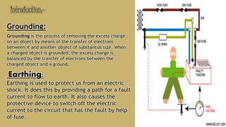
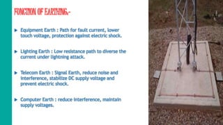


The document presents information on earthing systems. It discusses the functions of earthing, which include providing a path for fault currents and protection from electric shock. It describes various methods of earthing, including plate earthing, pipe earthing, and rod earthing. It also discusses different types of earthing systems and applications of earthing in electrical systems. In conclusion, it emphasizes the importance of proper grounding and earthing in electrical engineering for safety and protection of electrical equipment.


