Downloaded 1,457 times


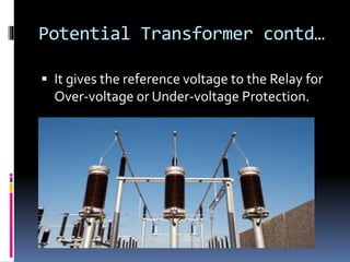


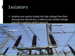


This presentation discusses the key protection devices used in electrical substations. It introduces current transformers and potential transformers, which reduce current and voltage levels for protection relays. Relays detect faults by measuring currents and voltages. When a fault is detected, relays signal circuit breakers to isolate the faulty component. Other protection devices discussed include lightning arresters, isolators, and surge diverters. The objective of the substation protection system is to isolate only faulty parts of the network while keeping the rest operational.


