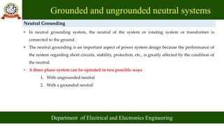
- The document discusses grounded and ungrounded neutral systems in power systems.
- In an ungrounded system, the neutral is isolated from ground which can cause overvoltages and issues with fault detection.
- Grounded systems connect the neutral to ground to limit voltages and improve safety, reliability and fault detection.
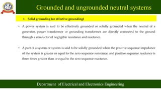
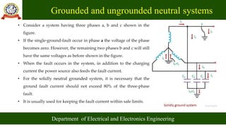
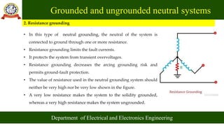
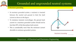
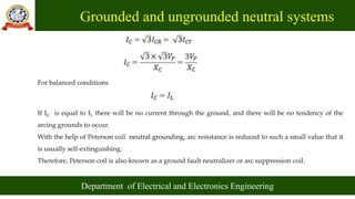
- Common methods for grounding the neutral include solid grounding, resistance grounding, reactance grounding and Peterson coil grounding. The selection depends on system size and protection requirements.