Downloaded 1,182 times

![REFERENCES
[1] R.C. Dugan, M.F. McGranaghan, and H.W. Beaty, “Electric Power Systems Quality,” McGraw-
Hill, 1996.
[2] “IEEE Recommended Practice for the Design of Reliable Industrial and Commercial Power
Systems,” IEEE Std. 493-1997, December 1997.
[3] IEEE Standards Board (1995), “IEEE Std. 1159-1995”, IEEE Recommended Practice for
Monitoring Electric Power Quality”. IEEE Inc. NewYork
[4] AmbraSannino. Mitigation of voltage sags and short interruptions through distribution system
design. Dept. of Electrical Engineering University of Palermo, pp 1-6,2000.
[5] David Chapman, Power Quality Application Guide - The Cost of Poor Power Quality, Copper
Development Association, 2001.
[6].Haque, M. H., "Compensation of distribution system voltage sag by DVR and
DSTATCOM,"Power Tech Proceedings, 2001 IEEE Porto , vol.1, no., pp.5 pp. vol.1,, 2001.
[7]Venkatesh, C.; Reddy, V.P.; Siva Sarma, D.V.S.S., "Mitigation of voltage sags/swells using PWM
switched autotransformer," Harmonics and Quality ofPower, 2008. ICHQP 2008. 13th
International Conference on , vol., no., pp.1,6, Sept. 28 2008-Oct. 1 2008.
[8] K. Chan, A. Kara, and G. Kieboom, “Power quality improvement with solid state transfer
switches,” in Proc. 8th ICHQP 1998, Athens, Greece, Oct. 1998, pp. 210-215](https://image.slidesharecdn.com/voltagesaganditsmitigation-151019144049-lva1-app6891/85/Voltage-sag-and-it-s-mitigation-18-320.jpg)

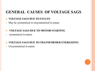
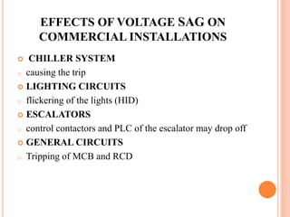
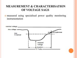
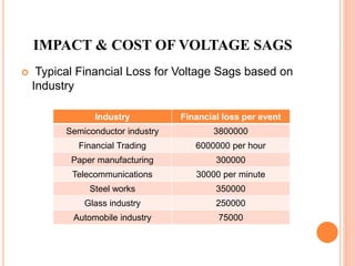
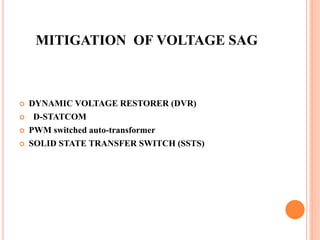
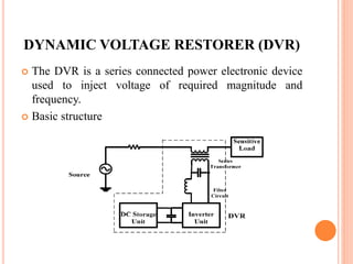
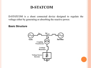
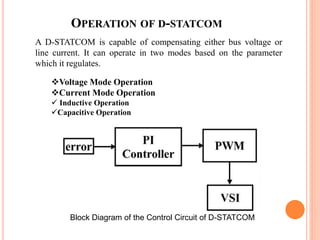
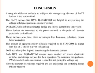
The document discusses voltage sag, which is a temporary reduction in voltage in power systems, and its causes, effects on commercial installations, and mitigation strategies. It highlights various types of sags, their impact on industries, and employs methods such as Dynamic Voltage Restorer (DVR) and D-STATCOM for mitigation. The conclusion emphasizes FACT devices as the best solutions, while also noting the advantages of using PWM switched auto-transformers for reduced switching losses.