Downloaded 6,699 times

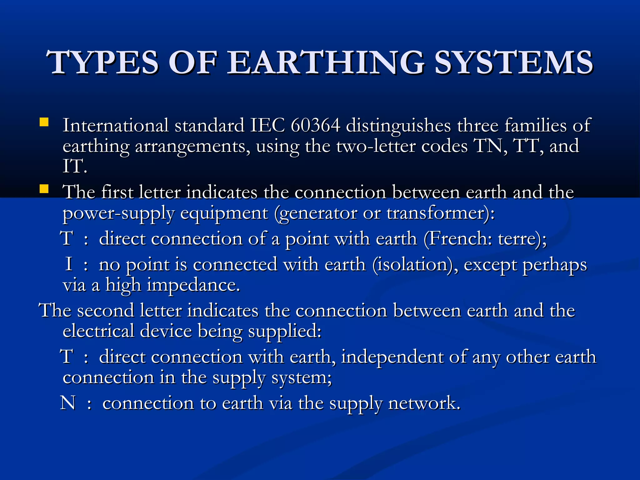
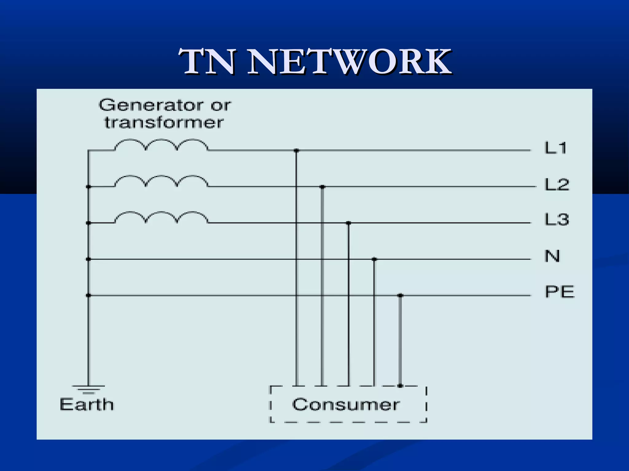
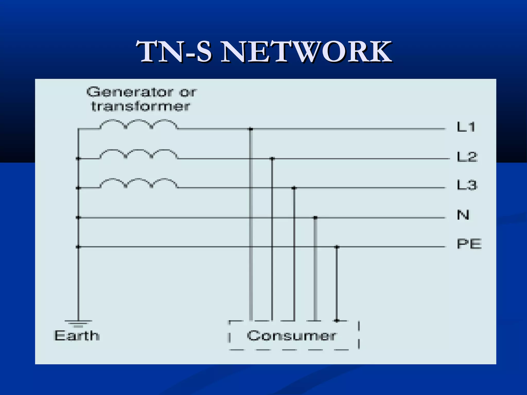
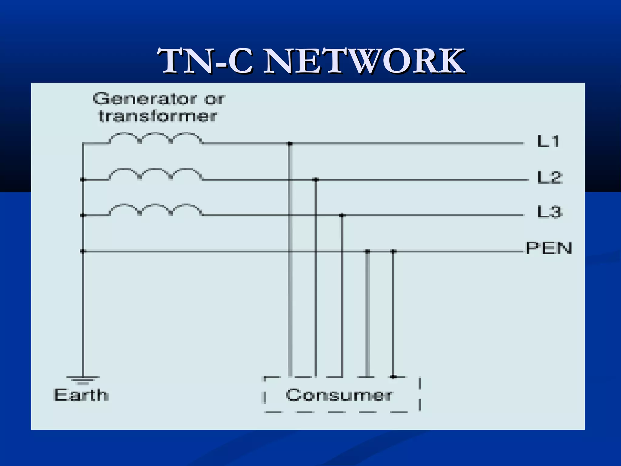
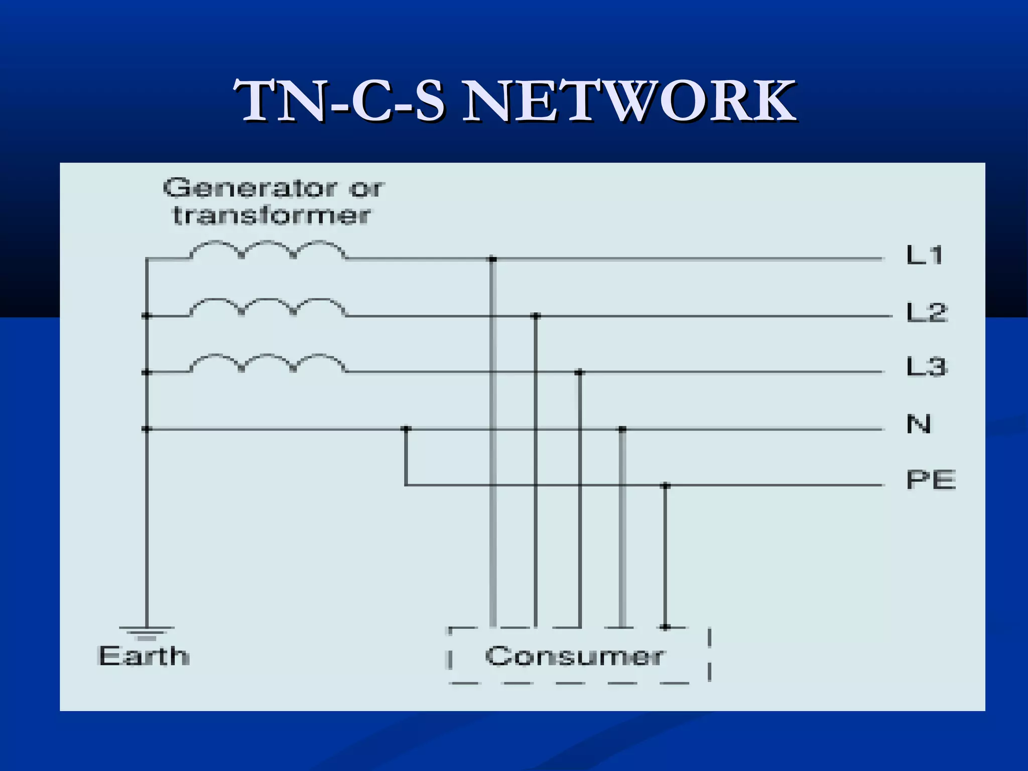
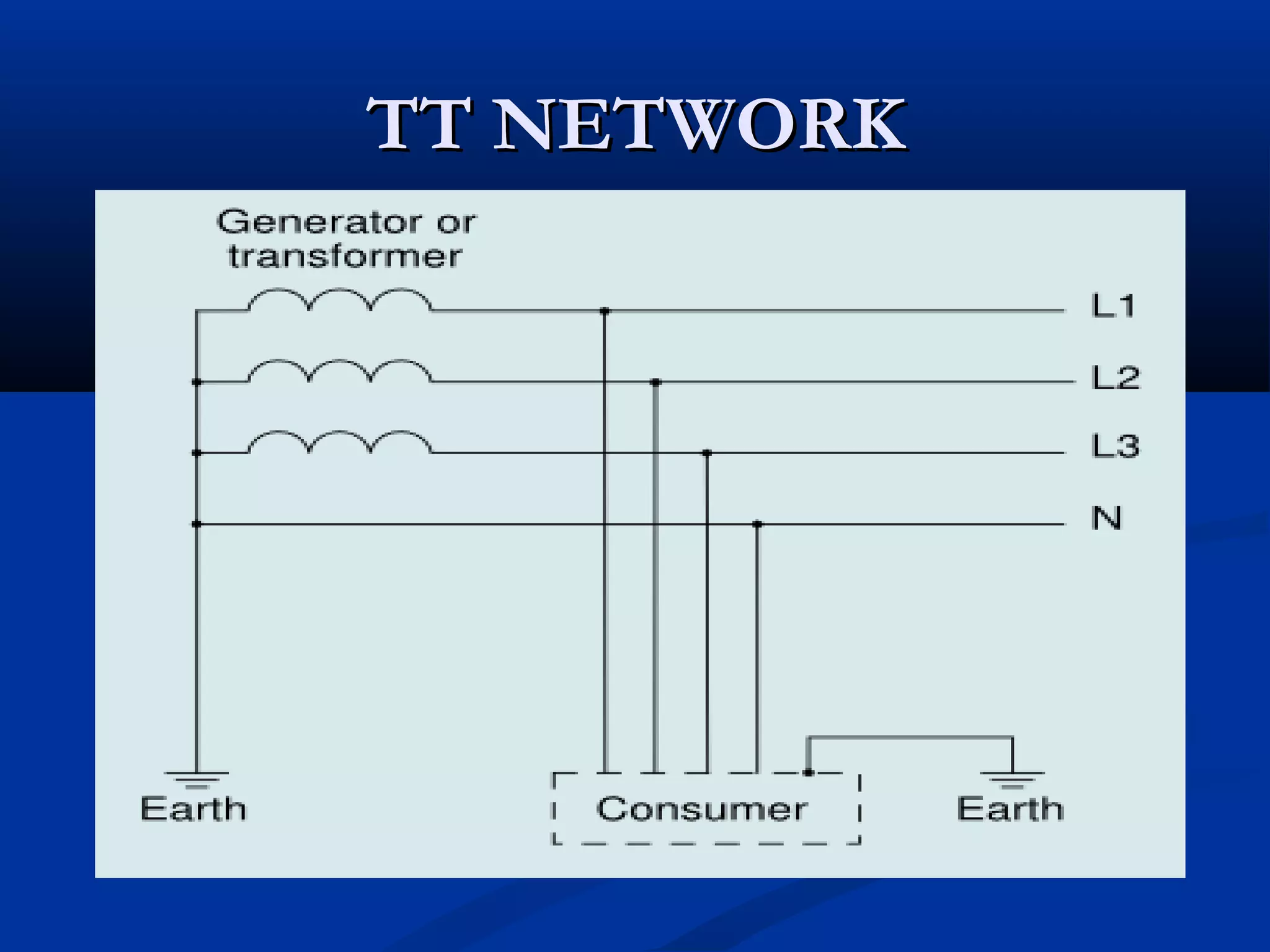
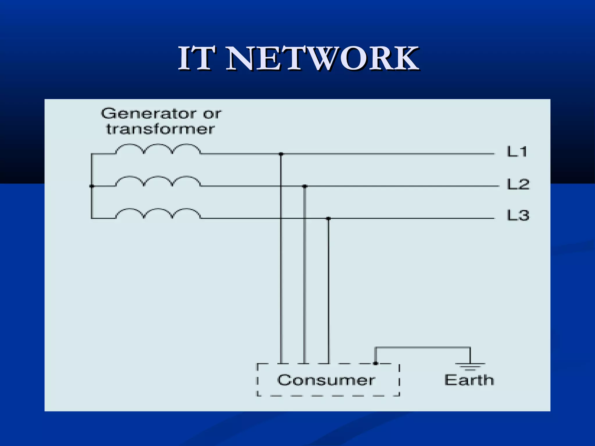


This document discusses electrical grounding and earthing systems. It begins by introducing grounding and earthing, and distinguishing between ground and neutral conductors. It then describes different types of earthing systems according to the IEC standard, including TN, TT, and IT networks. The document also covers different types of grounding used in radio communications, AC power installations, and lightning protection. It discusses the concept of virtual ground and multipoint grounding. Overall, the document provides an overview of electrical grounding and earthing systems, their uses, and important concepts.