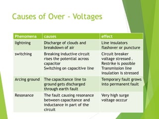
Transient
Over -
Voltage
Transient over –voltage
 Lightning over voltage
 Due to lightning surges
 Switching over voltage
 Sudden change in circuit
condition
 Switching
 Resonance
 Arcing grounds
Causes of Over - Voltages
Phenomena causes effect
lightning Discharge of clouds and
breakdown of air
Line insulators
flashover or puncture
switching Breaking inductive circuit
rises the potential across
capacitor
Switching on capacitive line
Circuit breaker
voltage stressed .
Restrike is possible
Transmission line
insulation is stressed
Arcing ground The capacitance line to
ground gets discharged
through earth fault
Temporary fault grows
into permanent fault
Resonance The fault causing resonance
between capacitance and
inductance in part of the
circuit
Very high surge
voltage occcur
LIGTHNING OVER-VOLTAGES
What is lightning?
The large spark accompanied by light
produced by an abrupt,
discontinuous discharge of electricity
through the air from the cloud under
turbulent condition
of atmosphere is called lightning
Some figures
 Voltage : 2x10⁸ volts, (200 MV)
 Current 4x44 A
 Duration : 10-5 seconds
 Power : 8x10 9 kW
 Energy : 22 kWh
 Lightning cannot be prevented, but it can with some
success be intercepted and its current conducted to
grounding system without side flashes
Direct lightning stroke
Form of the negative ground/cloud lightning
current
Lightning stroke possbilities
Direct flash (A stroke): The current can be
considered as an ideal current source. The
resulting Over voltage therefore depends on
the impedance seen by the current source. The
impedance is the surge impedance of the line
(200-400 ohm). Then a very high voltage
appears
Near flash (B stroke) : Due to change in electro-
magnetic field a voltage is induced the line. Ex:
in high voltage line with 10 m high for lightning
current of 30 kA, the induced voltage is in order
of 100 kV for a flash at 100 m distance
How does it effects?
 The lightning discharge causes
Thermal
Mechanical
Electrical
Effects to the system
Line insulators flashover or puncture. The travelling wave
reaches the substations and generating stations. The
insulation of equipment and machines stressed
Cont.
 Travelling wave: A lightning stroke terminating on a
power system initiates wave that propagate within the
system. To determine the resulting surge voltage and
current a travelling wave analysis is required
 Surge voltage: In general surge voltage and surge
current should be considered. The current exists only
microseconds. The surge voltage exceeds the insulation
strength a flashover occurs
Current and Voltage waves
A very steep front and rapid damping are
the characteristic of lightning
phenomena
Raising of earthing potential
When lightning current flows through the ground it affects to the
Earthing poential of electrical installtions
Over voltage caused by
coupling from other systems
Raise of eathing potential
V=0.2 Iρ/D
Where :
I: lightning current
ρ : soil resitivity
D : distance
If I=20 kA, ρ=1000 ohm/m
For D=100 m V=40 kV
D=50 m V=80 kV
Effect on LV
Principle of protection
Use of rod gap or spark gap
Rod gap
 Limitations
a. After the surge is over short circuit may occur
b. The rods may melt or get damaged due to excessive heat produced
by the arc.
c. The climatic conditions (e.g. rain, humidity, temperature etc.)
affect the performance of rod gap arrester.
d. The polarity of the f the surge also affects the performance of this
arrester.
e. Due to the above limitations, the rod gap arrester is only used as a
back-up protection in case of main arresters.
Horn gap
 The gap between horns is less at the bottom and largest
at the top. The arc is produced at the bottom during
high voltage. It moves up due to electromagnetic field
action and heat.
Arresters
 Lightning arrester is connected between line and earth.
Main elements are non-linear resistor unit and gap unit.
 At power frequency the resistor unit offers a very high
resistance and no current flows through the ground
 For discharge current the resistance is low and
breakdown occurs the gap.
Shielding
 Shielding masts are commonly used in substations, and
overhead ground wires are used in both substations and
on transmission lines
Use of earth wire
 The earth wire is at the top of the OH line and at every
and each tower the ground wire is earthed. The
negatively charged strokes are attracted by this wire.
Without ground wire the stroke hits the live conductors
which bring the disaster.
 It does not provide 100% protection against lightning
 Shielding angle of 35 % can be considered as satisfactory
Insulation co-ordination
 The correlation of the insulation of the equipment and
circuit with the characteristic of protective devices so
that the insulation is protected from the over voltages
 Normal voltage: r.m.s line to line voltage by which the
system is designed
 Highest voltage: highest r.m.s. line to line voltage which
can be sustained under normal operating conditions
Cont.
 Insulation level : combination of voltage values both
power frequency and impulse which characterize the
insulation of that equipment with regard to capability
of withstanding dielectric stress.
Coordinating the
characteristic
 Lightning arrester should have the lowest spark voltage.
The residual voltage should be less than transformer
insulation strength
 The voltage time curve of individual components must
be taken into account
 The insulation co-ordination should be based on worst
atmospheric conditions

D.pdf

  • 1.
  • 2.
    Transient over –voltage Lightning over voltage  Due to lightning surges  Switching over voltage  Sudden change in circuit condition  Switching  Resonance  Arcing grounds
  • 3.
    Causes of Over- Voltages Phenomena causes effect lightning Discharge of clouds and breakdown of air Line insulators flashover or puncture switching Breaking inductive circuit rises the potential across capacitor Switching on capacitive line Circuit breaker voltage stressed . Restrike is possible Transmission line insulation is stressed Arcing ground The capacitance line to ground gets discharged through earth fault Temporary fault grows into permanent fault Resonance The fault causing resonance between capacitance and inductance in part of the circuit Very high surge voltage occcur
  • 4.
  • 5.
    What is lightning? Thelarge spark accompanied by light produced by an abrupt, discontinuous discharge of electricity through the air from the cloud under turbulent condition of atmosphere is called lightning
  • 7.
    Some figures  Voltage: 2x10⁸ volts, (200 MV)  Current 4x44 A  Duration : 10-5 seconds  Power : 8x10 9 kW  Energy : 22 kWh  Lightning cannot be prevented, but it can with some success be intercepted and its current conducted to grounding system without side flashes
  • 8.
    Direct lightning stroke Formof the negative ground/cloud lightning current
  • 9.
  • 10.
    Direct flash (Astroke): The current can be considered as an ideal current source. The resulting Over voltage therefore depends on the impedance seen by the current source. The impedance is the surge impedance of the line (200-400 ohm). Then a very high voltage appears Near flash (B stroke) : Due to change in electro- magnetic field a voltage is induced the line. Ex: in high voltage line with 10 m high for lightning current of 30 kA, the induced voltage is in order of 100 kV for a flash at 100 m distance
  • 11.
    How does iteffects?  The lightning discharge causes Thermal Mechanical Electrical Effects to the system Line insulators flashover or puncture. The travelling wave reaches the substations and generating stations. The insulation of equipment and machines stressed
  • 12.
    Cont.  Travelling wave:A lightning stroke terminating on a power system initiates wave that propagate within the system. To determine the resulting surge voltage and current a travelling wave analysis is required  Surge voltage: In general surge voltage and surge current should be considered. The current exists only microseconds. The surge voltage exceeds the insulation strength a flashover occurs
  • 13.
    Current and Voltagewaves A very steep front and rapid damping are the characteristic of lightning phenomena
  • 14.
    Raising of earthingpotential When lightning current flows through the ground it affects to the Earthing poential of electrical installtions
  • 15.
    Over voltage causedby coupling from other systems
  • 16.
    Raise of eathingpotential V=0.2 Iρ/D Where : I: lightning current ρ : soil resitivity D : distance If I=20 kA, ρ=1000 ohm/m For D=100 m V=40 kV D=50 m V=80 kV
  • 17.
  • 18.
    Principle of protection Useof rod gap or spark gap
  • 19.
    Rod gap  Limitations a.After the surge is over short circuit may occur b. The rods may melt or get damaged due to excessive heat produced by the arc. c. The climatic conditions (e.g. rain, humidity, temperature etc.) affect the performance of rod gap arrester. d. The polarity of the f the surge also affects the performance of this arrester. e. Due to the above limitations, the rod gap arrester is only used as a back-up protection in case of main arresters.
  • 20.
    Horn gap  Thegap between horns is less at the bottom and largest at the top. The arc is produced at the bottom during high voltage. It moves up due to electromagnetic field action and heat.
  • 21.
    Arresters  Lightning arresteris connected between line and earth. Main elements are non-linear resistor unit and gap unit.  At power frequency the resistor unit offers a very high resistance and no current flows through the ground  For discharge current the resistance is low and breakdown occurs the gap.
  • 24.
    Shielding  Shielding mastsare commonly used in substations, and overhead ground wires are used in both substations and on transmission lines
  • 25.
    Use of earthwire  The earth wire is at the top of the OH line and at every and each tower the ground wire is earthed. The negatively charged strokes are attracted by this wire. Without ground wire the stroke hits the live conductors which bring the disaster.  It does not provide 100% protection against lightning  Shielding angle of 35 % can be considered as satisfactory
  • 26.
    Insulation co-ordination  Thecorrelation of the insulation of the equipment and circuit with the characteristic of protective devices so that the insulation is protected from the over voltages  Normal voltage: r.m.s line to line voltage by which the system is designed  Highest voltage: highest r.m.s. line to line voltage which can be sustained under normal operating conditions
  • 27.
    Cont.  Insulation level: combination of voltage values both power frequency and impulse which characterize the insulation of that equipment with regard to capability of withstanding dielectric stress.
  • 28.
    Coordinating the characteristic  Lightningarrester should have the lowest spark voltage. The residual voltage should be less than transformer insulation strength  The voltage time curve of individual components must be taken into account  The insulation co-ordination should be based on worst atmospheric conditions