Downloaded 309 times

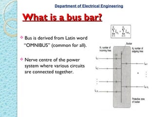
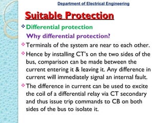
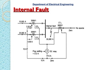
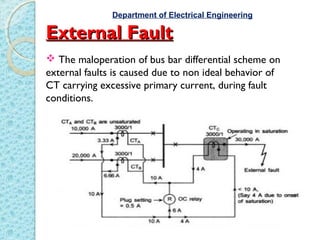


Bus bars are the nerve center of a power system where various circuits are connected. Differential protection is suitable for bus bars since terminals are near each other, allowing comparison of current entering and leaving via CTs. Any difference signals an internal fault and causes the relay coil to trip circuit breakers on both sides, isolating the bus. CT ratios for bus differential schemes equal the maximum feeder current divided by 1 or 5 amps. External faults may cause maloperation if a CT saturates, but a stabilizing resistance can restrain the relay. Dot convention defines the direction of current flow in CT secondaries. Only class PS CTs should be used to avoid undesired difference currents. Differential protection is important to protect bus bars


![protection of transmission lines[distance relay protection scheme]](https://cdn.slidesharecdn.com/ss_thumbnails/os-exe3-23-may2011-sr-i-776s21tr-lineprotection-120425095503-phpapp02-thumbnail.jpg?width=640&height=640&fit=bounds)


