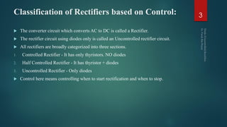
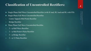
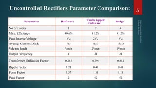
This document discusses different types of uncontrolled diode rectifiers. It begins by classifying rectifiers as controlled, half-controlled, or uncontrolled based on whether they use thyristors, thyristors and diodes, or only diodes, respectively. The document then describes various single-phase and three-phase uncontrolled rectifier circuits including half-wave, full-wave center-tap, full-wave bridge, and multiphase designs. Key parameters like efficiency, voltage, current, ripple, and frequency are defined for each rectifier type. Circuit diagrams and operating principles are provided to explain how the different rectifiers function.
It’s a power electronics project. It is able to give output voltage(DC) more and less than input voltage as per requirement.
We can generate variable DC voltage which is less than input, but, the special things about this converter is, it has capability to produce variable DC voltage as high as twice the input voltage.
We have specially designed and manufactured inductor for this project.
These slides provide an elementary description of Power Electronics and its application domains. It also shows the different power devices and converters.
This article discusses different power electronics devices that are in use like power diodes, power thyristors, power transistors, IGBT, GTO, IGCT and others. This article will give a basic view of these devices and their operations.
To turn on a Thyristor, there are various triggering methods in which a trigger pulse is applied at its Gate terminal. Similarly, there are various techniques to turn off a Thyristor, these techniques are called Thyristor Commutation Techniques.
A silicon-controlled rectifier or semiconductor-controlled rectifier is a four-layer solid-state current-controlling device. Some sources define silicon-controlled rectifiers and thyristors as synonymous,[5] other sources define silicon-controlled rectifiers as a proper subset of the set of thyristors. SCRs are mainly used in devices where the control of high power, possibly coupled with high voltage, is demanded. Their operation makes them suitable for use in medium- to high-voltage AC power control applications, such as lamp dimming, power regulators and motor control.
This ppt provides a brief overview on thyristors commonly known as SCRs. V- I characteristics curve, triggering methods, protection methods, series and parallel operations of SCRs, applications are discussed in this slide.
The inverter is a static device. It can convert one form of electrical power into other forms of electrical power. But it cannot generate electrical power. Hence the inverter is a converter, not a generator.
The three types of rectifiers in just 18 slides. Learn and enjoy the concepts. This PowerPoint presentation not only tells about the working and principles of rectifiers but also determines the disadvantages and advantages of different rectifiers. This PowerPoint presentation also has circuit diagrams that suit your necessities. This PPT can be written as an answer for a long type of question too.
A tunnel diode or Esaki diode is a type of semiconductor that is capable of very fast operation, well into the microwave frequency region, made possible by the use of the quantum mechanical effect called tunneling.
It was invented in August 1957 by Leo Esaki when he was with Tokyo Tsushin Kogyo, now known as Sony. In 1973 he received the Nobel Prize in Physics, jointly with Brian Josephson, for discovering the electron tunneling effect used in these diodes. Robert Noyce independently came up with the idea of a tunnel diode while working for William Shockley, but was discouraged from pursuing it.[1]
These diodes have a heavily doped p–n junction only some 10 nm (100 Å) wide. The heavy doping results in a broken bandgap, where conduction band electron states on the n-side are more or less aligned with valence band hole states on the p-side
Tunnel diodes were first manufactured by Sony in 1957[2] followed by General Electric and other companies from about 1960, and are still made in low volume today.[3] Tunnel diodes are usually made from germanium, but can also be made from gallium arsenide and silicon materials. They are used in frequency converters and detectors.[4] They have negative differential resistance in part of their operating range, and therefore are also used as oscillators, amplifiers, and in switching circuits using hysteresis.
Figure 6: 8–12 GHz tunnel diode amplifier, circa 1970
In 1977, the Intelsat V satellite receiver used a microstrip tunnel diode amplifier (TDA) front-end in the 14 to 15.5 GHz band. Such amplifiers were considered state-of-the-art, with better performance at high frequencies than any transistor-based front end.[5]
The highest frequency room-temperature solid-state oscillators are based on the resonant-tunneling diode (RTD).[6]
There is another type of tunnel diode called a metal–insulator–metal (MIM) diode, but present application appears restricted to research environments due to inherent sensitivities.[7] There is also a metal–insulator–insulator–metal MIIM diode which has an additional insulator layer. The additional insulator layer allows "step tunneling" for precise diode control.[8]
This article speaks about the different energy domains, sensors, actuation techniques, transduction techniques, fabrication materials, physical strength requirements, substrate materials and De Vries formula used in MEMS technology.
This article discusses MEMS, i.e. Micro-Electro Mechanical Systems.
It gives a rudimentry idea of MEMS technology, its block diagram, applications, advantages and disadvantages. It also gives a brief idea on the working principle of MEMS devices.
Basic concept and techniques of Flow measurement are described.
Bernoulli's Principle, Hagen Poiseuille Law, Coanda and Coriolis Effect are described..
Cosmetic shop management system project report.pdfKamal Acharya
Buying new cosmetic products is difficult. It can even be scary for those who have sensitive skin and are prone to skin trouble. The information needed to alleviate this problem is on the back of each product, but it's thought to interpret those ingredient lists unless you have a background in chemistry.
Instead of buying and hoping for the best, we can use data science to help us predict which products may be good fits for us. It includes various function programs to do the above mentioned tasks.
Data file handling has been effectively used in the program.
The automated cosmetic shop management system should deal with the automation of general workflow and administration process of the shop. The main processes of the system focus on customer's request where the system is able to search the most appropriate products and deliver it to the customers. It should help the employees to quickly identify the list of cosmetic product that have reached the minimum quantity and also keep a track of expired date for each cosmetic product. It should help the employees to find the rack number in which the product is placed.It is also Faster and more efficient way.
Automobile Management System Project Report.pdfKamal Acharya
The proposed project is developed to manage the automobile in the automobile dealer company. The main module in this project is login, automobile management, customer management, sales, complaints and reports. The first module is the login. The automobile showroom owner should login to the project for usage. The username and password are verified and if it is correct, next form opens. If the username and password are not correct, it shows the error message.
When a customer search for a automobile, if the automobile is available, they will be taken to a page that shows the details of the automobile including automobile name, automobile ID, quantity, price etc. “Automobile Management System” is useful for maintaining automobiles, customers effectively and hence helps for establishing good relation between customer and automobile organization. It contains various customized modules for effectively maintaining automobiles and stock information accurately and safely.
When the automobile is sold to the customer, stock will be reduced automatically. When a new purchase is made, stock will be increased automatically. While selecting automobiles for sale, the proposed software will automatically check for total number of available stock of that particular item, if the total stock of that particular item is less than 5, software will notify the user to purchase the particular item.
Also when the user tries to sale items which are not in stock, the system will prompt the user that the stock is not enough. Customers of this system can search for a automobile; can purchase a automobile easily by selecting fast. On the other hand the stock of automobiles can be maintained perfectly by the automobile shop manager overcoming the drawbacks of existing system.
Courier management system project report.pdfKamal Acharya
It is now-a-days very important for the people to send or receive articles like imported furniture, electronic items, gifts, business goods and the like. People depend vastly on different transport systems which mostly use the manual way of receiving and delivering the articles. There is no way to track the articles till they are received and there is no way to let the customer know what happened in transit, once he booked some articles. In such a situation, we need a system which completely computerizes the cargo activities including time to time tracking of the articles sent. This need is fulfilled by Courier Management System software which is online software for the cargo management people that enables them to receive the goods from a source and send them to a required destination and track their status from time to time.
Forklift Classes Overview by Intella PartsIntella Parts
Discover the different forklift classes and their specific applications. Learn how to choose the right forklift for your needs to ensure safety, efficiency, and compliance in your operations.
For more technical information, visit our website https://intellaparts.com
TECHNICAL TRAINING MANUAL GENERAL FAMILIARIZATION COURSEDuvanRamosGarzon1
AIRCRAFT GENERAL
The Single Aisle is the most advanced family aircraft in service today, with fly-by-wire flight controls.
The A318, A319, A320 and A321 are twin-engine subsonic medium range aircraft.
The family offers a choice of engines
Quality defects in TMT Bars, Possible causes and Potential Solutions.PrashantGoswami42
Maintaining high-quality standards in the production of TMT bars is crucial for ensuring structural integrity in construction. Addressing common defects through careful monitoring, standardized processes, and advanced technology can significantly improve the quality of TMT bars. Continuous training and adherence to quality control measures will also play a pivotal role in minimizing these defects.
Student information management system project report ii.pdfKamal Acharya
Our project explains about the student management. This project mainly explains the various actions related to student details. This project shows some ease in adding, editing and deleting the student details. It also provides a less time consuming process for viewing, adding, editing and deleting the marks of the students.
2. Contents:
Classification of Rectifiers
Performance Parameters of Rectifiers
1 – φ Half Wave Rectifier
1 – φ Full Wave Rectifier – Centre Tapped
1 – φ Full Wave Bridge Rectifier
3 – φ Uncontrolled Rectifier Classification
3 – φ Half Wave Rectifier
3 – φ Full Wave 6 Pulse Mid – Point Rectifier
3 – φ Full Wave Bridge Rectifier
3 – φ Full Wave 12 Pulse Rectifier
2
3. Classification of Rectifiers based on Control:
The converter circuit which converts AC to DC is called a Rectifier.
The rectifier circuit using diodes only is called an Uncontrolled rectifier circuit.
All rectifiers are broadly categorized into three sections.
1. Controlled Rectifier - It has only thyristors. NO diodes
2. Half Controlled Rectifier - It has thyristor + diodes
3. Uncontrolled Rectifier - Only diodes
Control here means controlling when to start rectification and when to stop.
3
4. Classification of Uncontrolled Rectifiers:
Single Phase Half Wave Uncontrolled Rectifier (with R load, RL load and RL with FD)
Single Phase Full Wave Uncontrolled Rectifier.
1. Centre Tapped (Mid Point) Rectifier
2. Bridge Rectifier
Three Phase Full Wave Uncontrolled Rectifier.
1. 3 – φ Half Wave Rectifier
2. 3 – φ Mid Point 6 Pulse Rectifier
3. 3 – φ Bridge Rectifier
4. 3 – φ 12 Pulse Rectifier
4
5. Uncontrolled Rectifiers Parameter Comparison:
Parameters Half-wave
Centre tapped
Full-wave
Bridge
No of Diodes 1 2 4
Max. Efficiency 40.6% 81.2% 81.2%
Peak Inverse Voltage VM 2VM VM
Average Current/Diode Idc Idc/2 Idc/2
Vdc (no load) Vm/π 2Vm/π 2Vm/π
Output Frequency f 2f 2f
Transformer Utilisation Factor 0.287 0.693 0.812
Ripple Factor 1.21 0.48 0.48
Form Factor 1.57 1.11 1.11
Peak Factor 2 √2 √2
5
6. Single Phase Half Wave Rectifier:
During each “positive” half cycle of the AC sine wave, the diode is forward biased as the
anode is positive with respect to the cathode resulting in current flowing through the
diode.
Since the DC load is resistive (resistor, R), the current flowing in the load resistor is
therefore proportional to the voltage (Ohm´s Law), and the voltage across the load resistor
will therefore be the same as the supply voltage, V s (minus V f), that is the “DC” voltage
across the load is sinusoidal for the first half cycle only so V out = V s.
During each “negative” half cycle of the AC sinusoidal input waveform, the diode is
reverse biased as the anode is negative with respect to the cathode.
6
7. Single Phase Half Wave Rectifier:
Therefore, NO current flows through the diode or circuit. Then in the negative half cycle
of the supply, no current flows in the load resistor as no voltage appears across it so
therefore, V out = 0
7
9. Single Phase Half Wave Rectifier (RL Load):
Current I 0 continues to flow even after source voltage V S is negative because of the
presence of inductance L in load.
After + ve half cycle, diode remains ON, so – ve half cycle appears across load current
until I 0 decays to zero at ωt = β.
When I 0 = 0 at ωt = β; V L = 0, V R = 0 and V S appears as reverse bias across diode D.
At β, diode voltage V D jumps from 0 to V M sin β where β > π.
Here β = γ is the conduction angle of the diode.
9
11. Single Phase Half Wave Rectifier (RL with FD):
Performance is improved by connecting FD across the load.
FD prevents o/p voltage from becoming –ve.
The load current waveform is more smooth and load performance is better.
System efficiency is improved as energy from L is transferred to R through FD.
𝐴𝑣. 𝑜𝑢𝑡𝑝𝑢𝑡 𝑉𝑜𝑙𝑡𝑎𝑔𝑒 𝑉0 =
1
2𝜋 0
𝜋
𝑉 𝑚 sin 𝜔𝑡 𝑑 𝜔𝑡 =
𝑉 𝑚
𝜋
; 𝐴𝑣. 𝐿𝑜𝑎𝑑 𝐶𝑢𝑟𝑟𝑒𝑛𝑡 𝐼0 =
𝑉 𝑚
𝜋𝑅
11
12. 1 – φ Full Wave Rectifier – Centre Tapped
Also called Mid – point rectifier.
The turns ration from each secondary to primary is taken as unity for simplicity.
When “A” is +ve w.r.t mid – point O, D1 conducts for π radians.
When “B” is +ve w.r.t mid – point O in the next half cycle, D2 conducts for the other π
radians.
Peak Inverse Voltage (PIV) for both D1 and D2 is 2 V S and hence it is called 1 – φ 2 –
pulse diode rectifier.
12
14. 1 – φ Full Wave Bridge Rectifier
On the positive half cycle of transformer secondary supply voltage, diodes D1 and D2
conduct, supplying this voltage to the load.
On the negative half cycle of supply voltage, diodes D3 and D4 conduct supplying this
voltage to the load.
It can be seen from the waveforms that the peak inverse voltage of the diodes is only V m
The average output voltage is the same as that for the centre - tapped transformer full-
wave rectifier.
𝑃𝑒𝑎𝑘 𝑅𝑒𝑝𝑒𝑡𝑖𝑡𝑖𝑣𝑒 𝐷𝑖𝑜𝑑𝑒 𝐶𝑢𝑟𝑟𝑒𝑛𝑡 𝐼 𝑚 =
𝑉 𝑚
𝑅
𝐴𝑣. 𝑂𝑢𝑡𝑝𝑢𝑡 𝑉𝑜𝑙𝑡𝑎𝑔𝑒 𝑉0 =
2𝑉 𝑚
𝜋
; 𝑅𝑀𝑆 𝑂𝑢𝑡𝑝𝑢𝑡 𝑉𝑜𝑙𝑡𝑎𝑔𝑒 𝑉 𝑟𝑚𝑠 = 2𝑉 𝑠
14
16. 3 – φ Uncontrolled Rectifier
3 – φ Rectifier offers the following advantages:
1. Higher o/p voltage for a given i/p voltage.
2. Lower amplitude ripples i.e. output voltage is smoother.
3. Higher frequency ripples simplifying filtering.
4. Higher overall efficiency.
16
17. 3 – φ Uncontrolled Rectifier: Classification
They are generally of four types.
1. 3 – φ Half – wave rectifier.
2. 3 – φ Mid – point 6 Pulse rectifier.
3. 3 – φ Bridge rectifier.
4. 3 – φ 12 Pulse rectifier.
17
18. 3 – φ Half – Wave Rectifier:
It uses a 3 – φ transformer with primary in delta and secondary in star connection.
D1, D2 and D3 have common connected cathode to common load R and all diodes are
oriented in different phases and therefore called as Common – Cathode Circuit.
18
19. 3 – φ Half – Wave Rectifier:
The rectifier element connected to the line at the highest +ve instantaneous voltage can
only conduct and pulsates between V max and 0.5 V max.
It is called 3 – φ 3 pulse rectifier as the o/p is repeated thrice in every cycle of V s.
The ripple frequency (f r) of the o/p voltage is
𝑓 𝑟
= 𝑛𝑓 𝑠
; 𝑛 = 𝑛𝑜. 𝑜𝑓 𝑑𝑖𝑜𝑑𝑒𝑠, 𝑓 𝑠
= 𝐴𝐶 𝑠𝑢𝑝𝑝𝑙𝑦 𝑓𝑟𝑒𝑞.
The ON diode connects its most +ve source terminal to the other two diode cathodes
keeping the other diodes OFF.
The sudden switchover from one diode to another is called “commutation”.
Each diode conducts for 120 º intervals.
Delta connection provides path for triplen (odd multiples of the 3rd harmonic) harmonic
currents stabilizing the voltage on star secondary.
19
21. 3 – φ Mid – Point 6 Pulse Rectifier:
A rectifier with more number of pulses will provide a smoothed out curve giving
improved performance and lesser ripples.
Delta – primary, Star – secondary transformer is used here.
The secondary of each pulse is in two halves.
The mid – point of all the secondary's are connected to form the neutral (n).
Six phase supplies are a1, c2, b1, a2, c1 and b2 terminals.
Phase voltages are 120 º apart from V a1, V b1 and V c1 and likewise for others.
V a1 – V a2, V b1 – V b2, V c1 – V c2 are 180 º apart.
Adjacent voltages are 60 º apart.
Diode that senses the highest +ve anode voltage conducts with a periodicity of 60 º .
21
24. 3 – φ Bridge Rectifier:
Two series diodes are always conducting while four diodes are blocking.
One of the conducting diodes is odd numbered while the other is even numbered.
Each diode conducts for 120 º.
Current flows out from the most +ve source terminal through an odd numbered diode
through the load followed by the even numbered diode and then back to the most –ve
source terminal.
Output has less ripples and the diodes are numbered in accordance to their conductance.
The bridge uses both the +ve and –ve halves of the i/p voltage.
Ripple frequency is 6*f.
Upper set of diodes constitutes the +ve group while the lower set constitutes the –ve.
Transformer Primary – Secondary is in Delta – Star configuration.
24
25. 3 – φ Bridge Rectifier:
The diode with the most +ve voltage will be conducting.
B is chosen as reference.
During 0º - 30º, the voltage at C is highest (arbitrarily). Hence D5 is conducting as it is
the most +ve.
Between 30º and 150º, A becomes the most +ve and hence conducting.
During 150º - 270º, B being most +ve conducts.
The cycle repeats itself.
Each diode conducts for 120º.
𝑂𝑢𝑡𝑝𝑢𝑡 𝑉𝑜𝑙𝑡𝑎𝑔𝑒 𝑉𝑂 =
1
𝜋 3 𝜋 3
2𝜋 3
𝑉𝑚 sin 𝜔𝑡𝑑 𝜔𝑡 =
3𝑉 𝑚
𝜋
= 0.955 ∗ 𝑉𝑚
𝑅𝑀𝑆 𝑉𝑜𝑙𝑡𝑎𝑔𝑒 𝑉𝑟𝑚𝑠 =
1
𝜋 3 𝜋 3
2𝜋 3
𝑉𝑚
2 𝑠𝑖𝑛2 𝜔𝑡𝑑(𝜔𝑡)
1
2
=
3𝑉 𝑚
𝜋
= 0.9558 ∗ 𝑉𝑚
25
28. 3 – φ 12 Pulse Rectifier:
With 12 pulses per cycle, the o/p waveform quality is much improved with high ripple
frequency.
12 pulse is constructed by connecting 2 6 – pulse rectifiers in series.
3 – φ AC source supplying to these two bridges are shifted by 30º w.r.t. each other and
this is achieved by using 2 3 – φ transformers, one is Y connection and other in Δ
connection, on the secondary side.
The two bridges are series connected having a summation of upper and lower rectifiers.
The secondary voltage of the Δ transformer is lesser by a factor of 3 to the Y transformer.
The problem is solved by having a √3 turn’s ration for Y – Δ transformer.
Ripple frequency is 12 times the source frequency.
𝑉0(𝑎𝑣𝑔.) =
𝑉 𝑚∗6 2
𝜋 3+1
= 0.989 ∗ 𝑉 𝑚; 𝑃𝐼𝑉 ≥ 3 ∗ 𝑉 𝑠
𝑉0 = 𝑉01 + 𝑉02
28