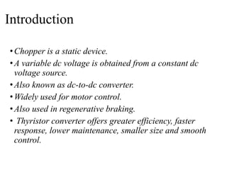
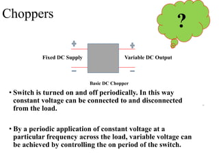
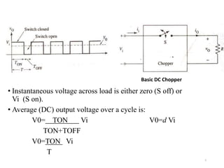
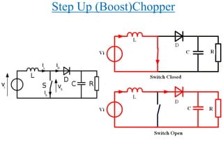
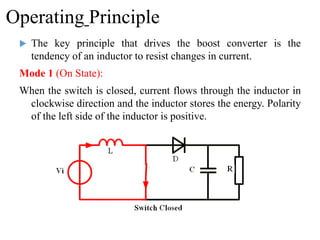
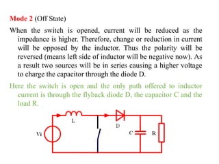
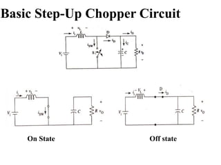
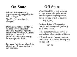
To turn on a Thyristor, there are various triggering methods in which a trigger pulse is applied at its Gate terminal. Similarly, there are various techniques to turn off a Thyristor, these techniques are called Thyristor Commutation Techniques.
This ppt provides a brief overview on thyristors commonly known as SCRs. V- I characteristics curve, triggering methods, protection methods, series and parallel operations of SCRs, applications are discussed in this slide.
Silicon Controlled Rectifier (SCR) is a unidirectional semiconductor device made of silicon.SCR is a three-terminal, four-layer semiconductor device consisting of alternate layers of p-type and n-type material.
Chopper basically uses a Thyristor for high power applications. The process of turning off a conducting Thyristor is known as commutation. Here Thyristor is turned off by a current pulse that is why it is called a Current Commutated Chopper.
INTRODUCTION
A chopper is a static device which is used to obtain a variable dc voltage from a
constant dc voltage source. A chopper is also known as dc-to-dc converter. The thyristor converter offers greater efficiency, faster response, lower maintenance, smaller size and smooth control. Choppers are widely used in trolley cars, battery operated vehicles, traction motor control, control of large number of dc motors, etc….. They are also used in regenerative braking of dc motors to return energy back to supply and also as dc voltage regulators.
Choppers are of two types
• Step-down choppers
• Step-up choppers.
In step-down choppers, the output voltage will be less than the input voltage
whereas in step-up choppers output voltage will be more than the input voltage.
Classification of Choppers:
(a) Depending upon the direction of the output current and voltage, the converters can be classified into five classes namely Class A [One-quadrant Operation] Class B [One-quadrant Operation] Class C [Two-quadrant Operation] Class D [Two-quadrant Operation] Class E [Four-quadrant Operation]
(b) Based on the output voltage of the output, the choppers are classified as
(i) Step-Down Chopper In this case the average output voltage is less than the input voltage. It is also known as step down converter
(ii) Step-Up Chopper Here the average output voltage is more than the input voltage. It is also known as step up converter
(iii) Step-Up/Down Chopper This type of converter produces an output voltage that is either lower or higher than the input voltage
(c) Depending upon the power loss occurred during turn ON/OFF of the switching device, the choppers are classified into two categories namely
(i) Hard switched Converter Here the power loss is high during the switching (ON to OFF and OFF to ON) as a result of the non zero voltage and current on the power switches.
(ii) Soft switched or resonant converters In this type of choppers, the power loss is low at the time of switching as a result of zero voltage and/or zero current on the switches.
2
PRINCIPLE OF STEP-DOWN CHOPPER
Figure 2.1 shows a step-down chopper with resistive load. The thyristor in the
circuit acts as a switch. When thyristor is ON, supply voltage appears across the load and
when thyristor is OFF, the voltage across the load will be zero. The output voltage and
current waveforms are as shown in figure 2.2.
Inverter is a device which convert a DC input supply voltage into symmetric AC voltage of desired magnitude and frequency at the output side. It is also know as DC-AC converter.
Ideal and practical inverter have sinusoidal and no-sinusoidal waveforms at output respectively.
If the input dc is a voltage source, the inverter is called a Voltage Source Inverter (VSI). One can similarly think of a Current Source Inverter (CSI), where the input to the circuit is a current source. The VSI circuit has direct control over ‘output (ac) voltage’ whereas the CSI directly controls ‘output (ac) current.
Self control of synchronous motor drives
Phase-Controlled Cycloconverters
Synchronous Motor Drive
Self controlled sync. Motor drive using a cycloconverter
Owen’s bridge and measurement of increment inductancevishalgohel12195
Owen’s bridge and measurement of increment inductance
Effect On Induced Voltage.
Measurements Of Incremental Inductance
Diagram Of Increment Inductance.
Description Of Ø-i Magnetizing Curve
Initial and final condition for circuit
Explain the transient response of a RC circuit
As the capacitor stores energy when there is:
a transition in a unit step function source, u(t-to)
or a voltage or current source is switched into the circuit.
Explain the transient response of a RL circuit
As the inductor stores energy when there is:
a transition in a unit step function source, u(t-to)
or a voltage or current source is switched into the circuit.
RC Circuit
RL Circuit
FSK , FM DEMODULATOR & VOLTAGE REGULATOR ICS
Application of PLL in FSK & FM demodulation three terminal regulator ics.
Adjustable output voltage regulator LM 317, LM 337 & LM 340 series power supply ics.
Basic design considerations for designed regulated power supply
Concept of general terms pertaining to rotating machinesvishalgohel12195
Concept of general terms pertaining to rotating machines
Physical concept of force and torque production.
Concept of general terms pertaining to rotating machines.
Generated emf in full pitched and short pitched winding.
Transfer Function and Mathematical Modeling
Transfer Function
Poles And Zeros of a Transfer Function
Properties of Transfer Function
Advantages and Disadvantages of T.F.
Translation motion
Rotational motion
Translation-Rotation counterparts
Analogy system
Force-Voltage analogy
Force-Current Analogy
Advantages
Example
Winding
What is Armature winding?
Terms related to armature winding.
Single layer and double layer windings.
Comparison between closed and open windings.
Types of DC armature winding.
Types of AC armature winding.
Protection against overvoltage
overvoltage
causes of overvoltage
lightning
types of lightning strokes
harmful effect of lightning
protection against lightning
On load tap changer in a.c. locomotive transformer & air blast circuit b...vishalgohel12195
On load tap changer In A.C. locomotive transformer & Air blast circuit breaker
Introduction
Block diagram of A.C. Locomotive
Equipment of locomotive & their function
Advantages
Disadvantages
Logical instruction of 8085
Instruction Set of 8085
Classification of Instruction Set
Logical Instructions
AND, OR, XOR
Logical Instructions
Summary Logical Group
Effect of non sinusoidal waveform of a.c. machine performancevishalgohel12195
Effect of Non sinusoidal waveform of A.C. Machine performance
Nonsinusoidal Waveforms
Key Similarities and Differences between Sinusoidal and Nonsinusoidal Waveforms
Effect of harmonics in motor drives
Square wave inverter with 180° mode
Effect of leakage reactance on the harmonic content of current
Parasitic torques due to non-sinusoidal voltages
Disadvantages of corona, radio interference, inductive interference between p...vishalgohel12195
Disadvantages of corona, radio interference, inductive interference between power and communication lines
Introduction
Disadvantages of corona.
Radio interference.
Inductive interference between power and communication lines
Design, Planning and Layout of high voltage laboratory vishalgohel12195
Design, Planning and Layout of high voltage laboratory
Test equipment provided in high voltage lab
Activity and study in high voltage lab
Classification of high voltage lab
Clearance of high voltage Lab
Layout of high voltage lab
Safety
Shielding of the high voltage lab
Design considerations of electrical installationsvishalgohel12195
Design considerations of electrical installations
Types of Loads
Estimation of load
Demand factor
Load factor
Diversity factor
Electric supply system
Overhead supply system
Underground cable system
Selection of type of wiring
Durability
Appearance
Cost
Safety
Accessibility
Maintenance cost
System of wiring
Welcome to WIPAC Monthly the magazine brought to you by the LinkedIn Group Water Industry Process Automation & Control.
In this month's edition, along with this month's industry news to celebrate the 13 years since the group was created we have articles including
A case study of the used of Advanced Process Control at the Wastewater Treatment works at Lleida in Spain
A look back on an article on smart wastewater networks in order to see how the industry has measured up in the interim around the adoption of Digital Transformation in the Water Industry.
Overview of the fundamental roles in Hydropower generation and the components involved in wider Electrical Engineering.
This paper presents the design and construction of hydroelectric dams from the hydrologist’s survey of the valley before construction, all aspects and involved disciplines, fluid dynamics, structural engineering, generation and mains frequency regulation to the very transmission of power through the network in the United Kingdom.
Author: Robbie Edward Sayers
Collaborators and co editors: Charlie Sims and Connor Healey.
(C) 2024 Robbie E. Sayers
Hierarchical Digital Twin of a Naval Power SystemKerry Sado
A hierarchical digital twin of a Naval DC power system has been developed and experimentally verified. Similar to other state-of-the-art digital twins, this technology creates a digital replica of the physical system executed in real-time or faster, which can modify hardware controls. However, its advantage stems from distributing computational efforts by utilizing a hierarchical structure composed of lower-level digital twin blocks and a higher-level system digital twin. Each digital twin block is associated with a physical subsystem of the hardware and communicates with a singular system digital twin, which creates a system-level response. By extracting information from each level of the hierarchy, power system controls of the hardware were reconfigured autonomously. This hierarchical digital twin development offers several advantages over other digital twins, particularly in the field of naval power systems. The hierarchical structure allows for greater computational efficiency and scalability while the ability to autonomously reconfigure hardware controls offers increased flexibility and responsiveness. The hierarchical decomposition and models utilized were well aligned with the physical twin, as indicated by the maximum deviations between the developed digital twin hierarchy and the hardware.
CFD Simulation of By-pass Flow in a HRSG module by R&R Consult.pptxR&R Consult
CFD analysis is incredibly effective at solving mysteries and improving the performance of complex systems!
Here's a great example: At a large natural gas-fired power plant, where they use waste heat to generate steam and energy, they were puzzled that their boiler wasn't producing as much steam as expected.
R&R and Tetra Engineering Group Inc. were asked to solve the issue with reduced steam production.
An inspection had shown that a significant amount of hot flue gas was bypassing the boiler tubes, where the heat was supposed to be transferred.
R&R Consult conducted a CFD analysis, which revealed that 6.3% of the flue gas was bypassing the boiler tubes without transferring heat. The analysis also showed that the flue gas was instead being directed along the sides of the boiler and between the modules that were supposed to capture the heat. This was the cause of the reduced performance.
Based on our results, Tetra Engineering installed covering plates to reduce the bypass flow. This improved the boiler's performance and increased electricity production.
It is always satisfying when we can help solve complex challenges like this. Do your systems also need a check-up or optimization? Give us a call!
Work done in cooperation with James Malloy and David Moelling from Tetra Engineering.
More examples of our work https://www.r-r-consult.dk/en/cases-en/
Cosmetic shop management system project report.pdfKamal Acharya
Buying new cosmetic products is difficult. It can even be scary for those who have sensitive skin and are prone to skin trouble. The information needed to alleviate this problem is on the back of each product, but it's thought to interpret those ingredient lists unless you have a background in chemistry.
Instead of buying and hoping for the best, we can use data science to help us predict which products may be good fits for us. It includes various function programs to do the above mentioned tasks.
Data file handling has been effectively used in the program.
The automated cosmetic shop management system should deal with the automation of general workflow and administration process of the shop. The main processes of the system focus on customer's request where the system is able to search the most appropriate products and deliver it to the customers. It should help the employees to quickly identify the list of cosmetic product that have reached the minimum quantity and also keep a track of expired date for each cosmetic product. It should help the employees to find the rack number in which the product is placed.It is also Faster and more efficient way.
Hybrid optimization of pumped hydro system and solar- Engr. Abdul-Azeez.pdffxintegritypublishin
Advancements in technology unveil a myriad of electrical and electronic breakthroughs geared towards efficiently harnessing limited resources to meet human energy demands. The optimization of hybrid solar PV panels and pumped hydro energy supply systems plays a pivotal role in utilizing natural resources effectively. This initiative not only benefits humanity but also fosters environmental sustainability. The study investigated the design optimization of these hybrid systems, focusing on understanding solar radiation patterns, identifying geographical influences on solar radiation, formulating a mathematical model for system optimization, and determining the optimal configuration of PV panels and pumped hydro storage. Through a comparative analysis approach and eight weeks of data collection, the study addressed key research questions related to solar radiation patterns and optimal system design. The findings highlighted regions with heightened solar radiation levels, showcasing substantial potential for power generation and emphasizing the system's efficiency. Optimizing system design significantly boosted power generation, promoted renewable energy utilization, and enhanced energy storage capacity. The study underscored the benefits of optimizing hybrid solar PV panels and pumped hydro energy supply systems for sustainable energy usage. Optimizing the design of solar PV panels and pumped hydro energy supply systems as examined across diverse climatic conditions in a developing country, not only enhances power generation but also improves the integration of renewable energy sources and boosts energy storage capacities, particularly beneficial for less economically prosperous regions. Additionally, the study provides valuable insights for advancing energy research in economically viable areas. Recommendations included conducting site-specific assessments, utilizing advanced modeling tools, implementing regular maintenance protocols, and enhancing communication among system components.
3. Introduction
•Chopper is a static device.
•A variable dc voltage is obtained from a constant dc
voltage source.
•Also known as dc-to-dc converter.
•Widely used for motor control.
•Also used in regenerative braking.
• Thyristor converter offers greater efficiency, faster
response, lower maintenance, smaller size and smooth
control.
4. • Switch is turned on and off periodically. In this way
constant voltage can be connected to and disconnected
from the load.
• By a periodic application of constant voltage at a
particular frequency across the load, variable voltage can
be achieved by controlling the on period of the switch.
4
Basic DC Chopper
Choppers
Fixed DC Supply Variable DC Output
?
5. • Instantaneous voltage across load is either zero (S off) or
Vi (S on).
• Average (DC) output voltage over a cycle is:
V0= TON Vi V0=d Vi
TON+TOFF
V0=TON Vi
T
5
Basic DC Chopper
6. Output voltage as
function of duty cycle
Output voltage varies linearly with duty cycle.
It is possible to control output voltage from zero to
Vi as duty cycle varies from zero to 1.
7. Methods Of Control
•The output dc voltage can be varied by
the following methods.
•Pulse width modulation control or
constant frequency operation.
•Variable frequency control.
8. Methods for varying Average
Output Voltage
Pulse-Width Modulation
• Pulse width TON is varied
while overall switching
period is kept constant.
Pulse-Frequency Modulation
• Pulse width TON is kept
constant while the period
(frequency) is varied.
9. Choppers are of Two Types
Step-down choppers.
Step-up choppers.
In step down chopper output voltage is less than
input voltage.
In step up chopper output voltage is more than
input voltage.
11. Operating Principle
The key principle that drives the boost converter is the
tendency of an inductor to resist changes in current.
Mode 1 (On State):
When the switch is closed, current flows through the inductor in
clockwise direction and the inductor stores the energy. Polarity
of the left side of the inductor is positive.
12. Mode 2 (Off State)
When the switch is opened, current will be reduced as the
impedance is higher. Therefore, change or reduction in current
will be opposed by the inductor. Thus the polarity will be
reversed (means left side of inductor will be negative now). As
a result two sources will be in series causing a higher voltage
to charge the capacitor through the diode D.
Here the switch is open and the only path offered to inductor
current is through the flyback diode D, the capacitor C and the
load R.
13. Continuous Current Mode
As elements are ideal,
DC power drawn from
source must equal the
DC power absorbed by
load.
P0 = Pi
V0 I0 = Vi Ii
I0 =Vi * Ii
V0
=Vi * Ii
Vi d
I0 = Ii_
16. On-State
• When S is on (D is off),
capacitor energy supplies the
load voltage.
Vo=Vc (if capacitor is
charged)
• During on-state of switch S,
voltage across inductor
instantly becomes equal to
input supply voltage. Current
through it increases
gradually and stores energy
in its magnetic field.
• For very first time, when S is
closed Vo=0, as capacitor is
not charged.
Off-State
• When S is off (D is on), inductor
voltage reverses its polarity and
adds in input voltage to provide
output voltage which is equal to:
V0=Vi+VL
• During off state of S, capacitor
charges and voltage at it gradually
build up to Vi+VL
(This capacitor voltages serves as
load voltage when next time S in on)
• If S is off forever, inductor acts as
short circuit. It does not develop any
voltage and
Vo= Vi
17. Application
Chopper are used for DC motor control( battery - supplied
vehicles),
Solar and Wind energy conservation
It’s also used in electric cars.
Airplane and spaceships ,where onboard-regulated DC
power supplies are required.
Chopper circuits are used as power supplies in computers,
commercial electronics, electronics instruments.