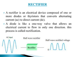
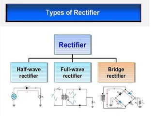
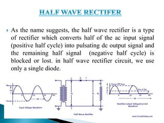
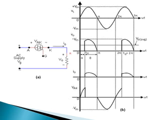
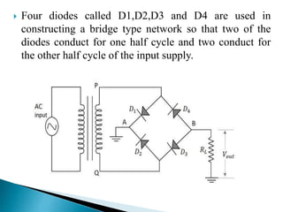
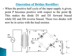
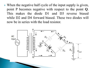
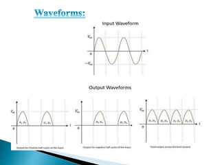
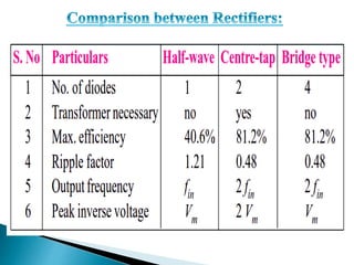
The presentation consists of the detailed explanation on the topic of Converters, specifically on the rectifiers, different types of rectifiers ( Half-wave, full-wave and bridge ) configuration. The advantages and disadvantages of rectifiers and their applications
The three types of rectifiers in just 18 slides. Learn and enjoy the concepts. This PowerPoint presentation not only tells about the working and principles of rectifiers but also determines the disadvantages and advantages of different rectifiers. This PowerPoint presentation also has circuit diagrams that suit your necessities. This PPT can be written as an answer for a long type of question too.
This is a presentation by Dada Robert in a Your Skill Boost masterclass organised by the Excellence Foundation for South Sudan (EFSS) on Saturday, the 25th and Sunday, the 26th of May 2024.
He discussed the concept of quality improvement, emphasizing its applicability to various aspects of life, including personal, project, and program improvements. He defined quality as doing the right thing at the right time in the right way to achieve the best possible results and discussed the concept of the "gap" between what we know and what we do, and how this gap represents the areas we need to improve. He explained the scientific approach to quality improvement, which involves systematic performance analysis, testing and learning, and implementing change ideas. He also highlighted the importance of client focus and a team approach to quality improvement.
How to Make a Field invisible in Odoo 17Celine George
It is possible to hide or invisible some fields in odoo. Commonly using “invisible” attribute in the field definition to invisible the fields. This slide will show how to make a field invisible in odoo 17.
Read| The latest issue of The Challenger is here! We are thrilled to announce that our school paper has qualified for the NATIONAL SCHOOLS PRESS CONFERENCE (NSPC) 2024. Thank you for your unwavering support and trust. Dive into the stories that made us stand out!
The French Revolution, which began in 1789, was a period of radical social and political upheaval in France. It marked the decline of absolute monarchies, the rise of secular and democratic republics, and the eventual rise of Napoleon Bonaparte. This revolutionary period is crucial in understanding the transition from feudalism to modernity in Europe.
For more information, visit-www.vavaclasses.com
We all have good and bad thoughts from time to time and situation to situation. We are bombarded daily with spiraling thoughts(both negative and positive) creating all-consuming feel , making us difficult to manage with associated suffering. Good thoughts are like our Mob Signal (Positive thought) amidst noise(negative thought) in the atmosphere. Negative thoughts like noise outweigh positive thoughts. These thoughts often create unwanted confusion, trouble, stress and frustration in our mind as well as chaos in our physical world. Negative thoughts are also known as “distorted thinking”.
2. Converters are electrical devices which converts one
form of electrical supply to other form using
semiconductor switches.
Different switches used in converters are: Diodes,
transistors or thyristors
3. Diode Rectifiers: Rectifier circuit converts AC input
voltage into a fixed DC voltage. This are also called
Uncontrolled rectifiers.
Phase Controlled Rectifiers: It converts fixed AC
voltage to a variable DC output voltage. These are also
called Controlled Rectifiers.
Choppers: It converts fixed dc input voltage to variable
DC output voltage. It is also called DC-DC converters.
4. Inverters: It converts a fixed DC voltage to an voltage
of variable frequency. It is also called DC-AC converter.
AC converters or Cycloconverters: It converts input
AC power of one frequency to output AC power to
different frequency. It is also called AC-AC converters.
AC Voltage controllers ( AC regulators): It converts
fixed AC voltage to a variable AC voltage at same
frequency using line commutation.
5. A rectifier is an electrical device composed of one or
more diodes or thyristors that converts alternating
current (ac) to direct current (dc).
A diode is like a one-way valve that allows an
electrical current to flow in only one direction. this
process is called rectification.
6.
7. As the name suggests, the half wave rectifier is a type
of rectifier which converts half of the ac input signal
(positive half cycle) into pulsating dc output signal and
the remaining half signal (negative half cycle) is
blocked or lost. in half wave rectifier circuit, we use
only a single diode.
8. It consists of a transformer and a diode D1.
The AC input voltage is applied to the transformer.
Positive ( +ve) supply is applied to the upper end of the
transformer and negative (-ve) supply is applied to the
lower end of the transformer.
The diode D1 is forward biased and conducts, hence the
current flows through the diode D1 through the load
Resistor RL during positive half cycle of AC input
voltage.
9.
10. 1) Cheap.
2) Easy to construct.
3) Simple.
The output current in the load contains, in addition to
dc component, ac components of basic frequency
equal to that of the input voltage frequency. Ripple
factor is high and an elaborate filtering is, therefore,
required to give steady dc output.
11. The power output and, therefore, rectification
efficiency is quite low. This is due to the fact that
power is delivered only during one-half cycle of the
input alternating voltage.
Transformer utilization factor is low.
. DC saturation of the transformer core resulting in
magnetizing current and hysteresis losses and
generation of harmonics.
12. A full wave rectifier is a circuit, which converts an ac
voltage into a pulsating dc voltage using both half cycles of
the applied ac voltage.
it uses two diodes of which one conducts during one
half cycle while the other conducts during the other half
cycle of the applied ac voltage.
It consists of transformer, two diodes and a load resistor
RL
13.
14. During positive half cycle of AC input voltage
terminal ‘A’ of secondary of the transformer is positive
(+ve) and terminal ‘B’ of the transformer secondary is
negative.
Diode D1 will be forward biased and conducts, where
as diode D2 is reversed biased and turned off.
The current flows through A-D1-RL-to centre tapped
of secondary
15. During negative half cycle of AC input voltage
terminal ‘A’ of secondary of the transformer is negative
(-ve) and terminal ‘B’ of the transformer secondary is
positive (+ve).
Diode D2 will be forward biased and conducts, where
as diode D1 is reversed biased and turned off.
The current flows through B-D2-RL-to centre tapped
of secondary
16.
17. The ripple frequency is two times the input frequency.
Efficiency is higher.
Ripple factor is less.
The ripple voltage is low and the higher frequency in
case full-wave rectifier so simple filtering circuit is
required.
Higher output voltage.
Utilizes both halves of the AC waveform.
18. More complicated than half-wave rectifier.
It requires more diodes.
The cost of the center tap transformer is high.
This rectifier is difficult to locate the center tap
on the secondary winding.
The DC output is small as using each of diode
utilized only one-half of the transformer
secondary voltages.
When a small voltage is required to be
rectified, the full-wave rectifier circuit is not
suitable.
19. Bridge rectifier circuit utilizes four diodes connected in
bridge form so as not only to produce the output during
the full cycle of input, but also to eliminate the
disadvantages of the center-tapped full wave rectifier
circuit.
There is no need of any center-tapping of the transformer
in this circuit.
20. Four diodes called D1,D2,D3 and D4 are used in
constructing a bridge type network so that two of the
diodes conduct for one half cycle and two conduct for
the other half cycle of the input supply.
21. When the positive half cycle of the input supply is given,
point P becomes positive with respect to the point Q.
This makes the diode D1 and D3 forward biased
while D2 and D4 reverse biased. These two diodes will
now be in series with the load resistor.
22. When the negative half cycle of the input supply is given,
point P becomes negative with respect to the point Q.
This makes the diode D1 and D3 reverse biased
while D2 and D4 forward biased. These two diodes will
now be in series with the load resistor.
23.
24. From the figure, it is evident that the output is
obtained for both the positive and negative half cycles.
It is also observed that the output across the load
resistor is in the same direction for both the half
cycles.
No need of center-tapping.
The dc output voltage is twice that of the center-tapper
FWR.
The design of the circuit is easier with better output.
25.
26. 1) Used in Industries.
2) Used in DC traction System.
3) Used in high voltage DC transmission system.
4) Used in inverters.
5) Used in Battery Chargers.
6) Used in motor drives