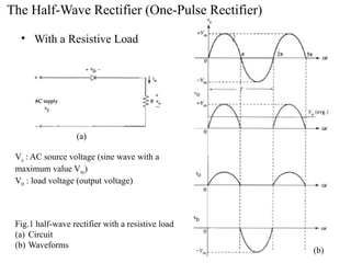
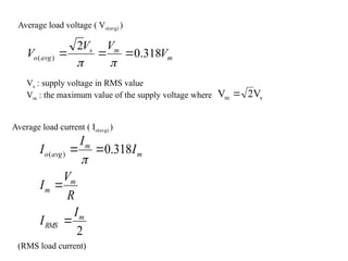
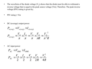
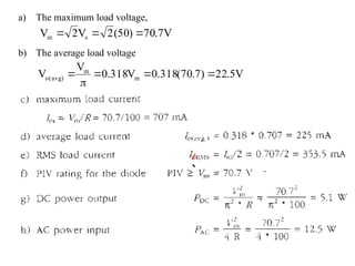
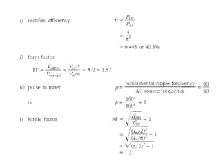
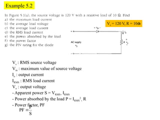
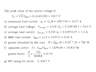
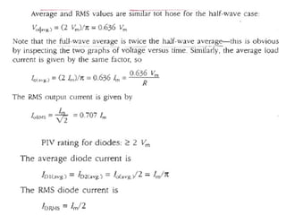
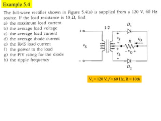
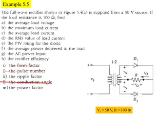
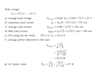
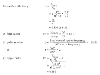
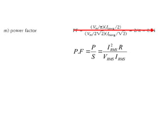
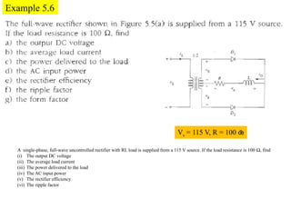
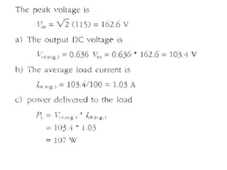
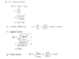
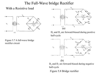
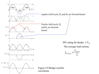
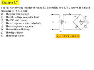
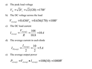
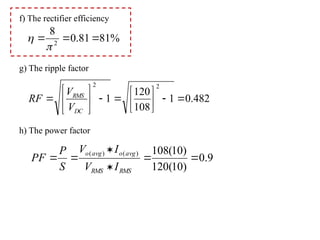
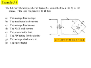
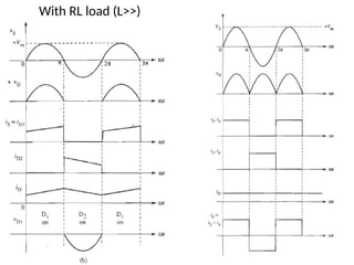
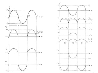
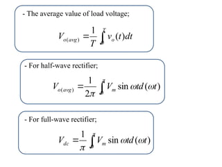
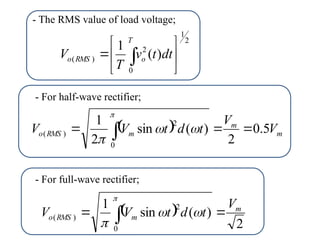
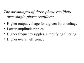
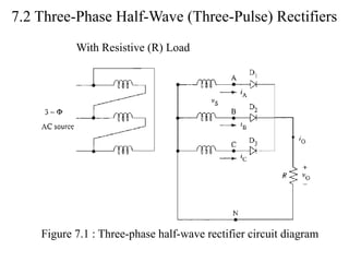
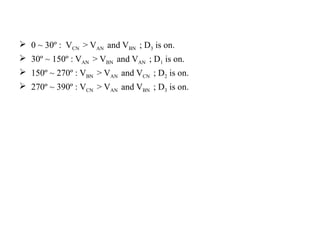
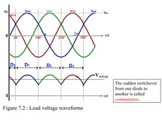
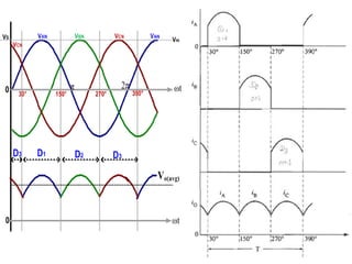
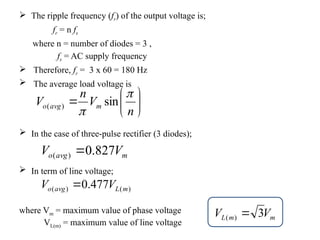
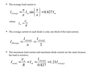
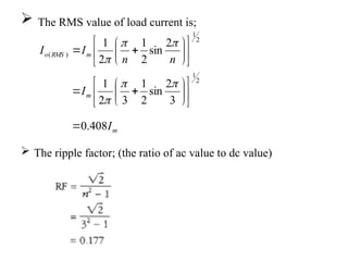
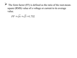
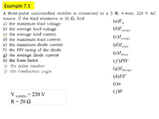
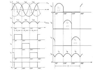
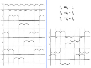
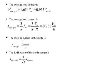
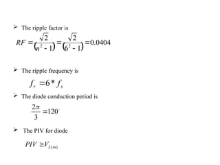
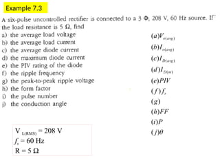
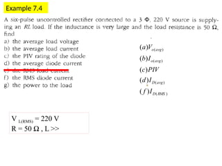
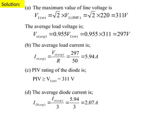
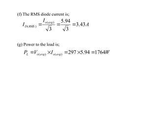
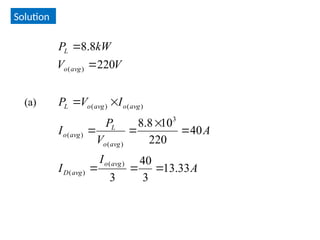
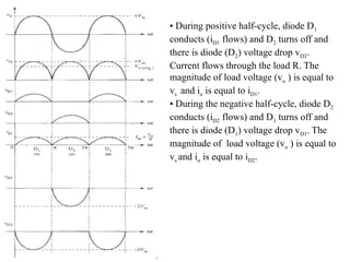
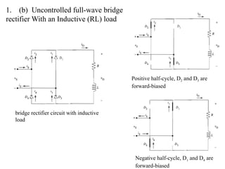
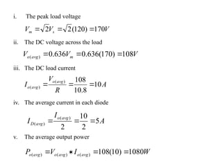
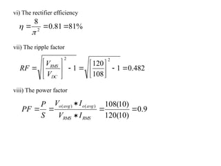
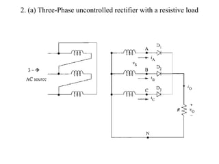
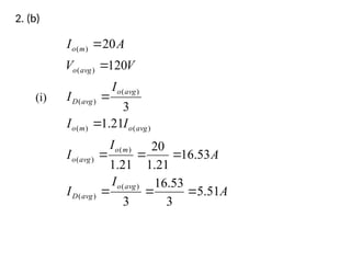
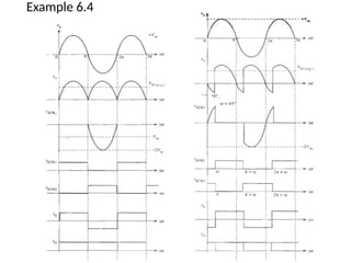
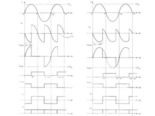
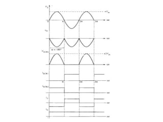
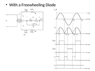
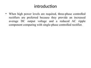
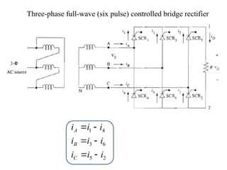
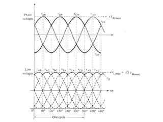
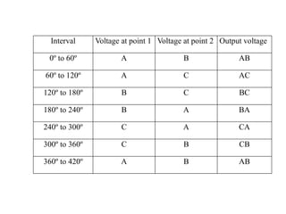
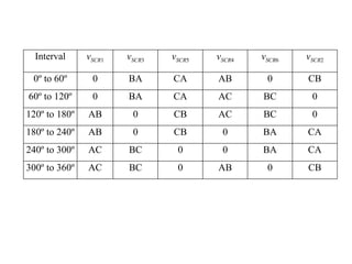
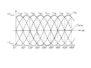
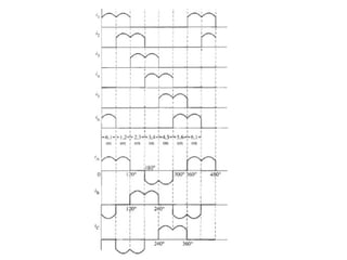
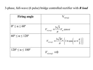
-Uncontrolled rectifiers convert a single-phase or three-phase AC voltage to a fixed
DC voltage.
-Rectification is the process of converting alternating current or voltage into direct
current or voltage.
- It uses only diodes as the rectifying elements.
Single-Phase Uncontrolled Rectifiers
To check rms value of 2 and sqrt.2
• With a Resistive Load
The Half-Wave Rectifier (One-Pulse Rectifier)
Fig.1 half-wave rectifier with a resistive load
(a) Circuit
(b) Waveforms
(a)
(b)
Vs : AC source voltage (sine wave with a
maximum value Vm)
V0 : load voltage (output voltage)
Average load voltage ( Vo(avg) )
m
m
s
avg
o V
V
V
V 318
.
0
2
)
( 




Vs : supply voltage in RMS value
Vm : the maximum value of the supply voltage where
Average load current ( Io(avg) )
2
318
.
0
)
(
m
RMS
m
m
m
m
avg
o
I
I
R
V
I
I
I
I





(RMS load current)
s
m V
2
V 
• The waveform of the diode voltage (VD) shows that the diode must be able to withstand a
reverse voltage that is equal to the peak source voltage (Vm). Therefore. The peak inverse
voltage (PIV) rating is given by;
• PIV rating ≥ Vm
• DC (average) output power
• AC input power
R
V
R
V
V
I
V
P
I
V
P
m
m
m
m
m
avg
o
avg
o
avg
o
avg
o
2
2
)
(
)
(
)
(
)
(












R
V
R
V
V
I
V
P
I
V
P
m
m
m
m
m
AC
RMS
RMS
AC
4
2
2
2
2
2







• The rectifier efficiency is defined as the ratio of DC output
power to AC input power.
• The form factor (FF) is a measure of the goodness of the shape
of the output voltage. It is defined as the ratio of the RMS
output voltage to the average value of output voltage.
AC
avg
o
P
P )
(


)
(
)
(
avg
o
RMS
o
V
V
FF 
• The output voltage of a rectifier contains both DC and AC (ripple)
components. The frequency and magnitude of the ripple voltage is an
important factor in the choice of rectifiers. The higher the frequency and
the smaller the magnitude of the ripple, the easier it is to filter the ripple to
within acceptable limits.
• The pulse number is the ratio of the fundamental ripple frequency of the
DC voltage to the frequency of the AC supply voltage.
• ripple factor (RF);
Pulse number p =
Fundamental ripple frequency
AC source frequency
DC
AC
I
I
RF 
s
r
f
f

• Power dissipated in the load resistor R
 
1
1
)
(
2
2
2
2
2
2
2
2
2
2
2
2
2
2
2
2
2












DC
RMS
DC
RMS
DC
DC
DC
RMS
DC
AC
DC
RMS
AC
AC
DC
RMS
L
I
I
RF
I
I
RF
I
I
I
I
I
I
I
I
I
OR
R
I
I
R
I
P
Example 5.1
Figure 5.1 (a)
Vs = 50 V
R = 100 Ω
(a) Vm = ?
(b) Vo(avg) = ?
(c) Im = ?
(d) Io(avg) = ?
(e) Io(RMS) = ?
(f) PIV = ?
(g) PDC = ?
(h) PAC = ?
(i) = ?
ɳ
(j) FF = ?
(k) Pulse number = ?
fs =60 Hz
fr = 60 Hz
a) The maximum load voltage,
b) The average load voltage
V
7
.
70
)
50
(
2
V
2
V s
m 


V
5
.
22
)
7
.
70
(
318
.
0
V
318
.
0
V
V m
m
)
avg
(
o 




Vs : RMS source voltage
Vm : maximum value of source voltage
Io : output current
IRMS : RMS load current
Vo : output voltage
- Apparent power S = VRMS  IRMS
- Power absorbed by the load P = IRMS
2
 R
- Power factor, PF
S
P
PF 
Example 5.2
Vs = 120 V, R = 10
With an Inductive (RL) Load
Figure 5.2 Half-wave rectifier with
inductive load
(a) Circuit
(b) Voltage and current waveforms
2

• The average value of the load voltage;
where  is conduction angle ( = 
+ )
• The average load current;
)
cos
1
(
2
V
V m
)
avg
(
o 



)
cos
1
(
R
2
V
I m
)
avg
(
o 



With an Inductive load and a Freewheeling Diode (FWD)
Figure 5.3 Half-wave rectifier with
inductive load and a FWD
(a) Circuit
(b) Typical waveforms with large
inductive load
FWD
Example 5.3
Vs = 240 V, R = 10
V
108
)
4
.
339
(
318
.
0
V
V
4
.
339
)
240
(
2
V
2
V
V
318
.
0
V
)
avg
(
o
s
m
m
)
avg
(
o






a) The average load voltage;
b) The average load current;
A
8
.
10
10
108
R
V
I )
avg
(
o
)
avg
(
o 


c) Due to the large value of the load inductance, the load current is nearly constant.
The RMS value of the load current therefore equals its average value. Therefore,
A
8
.
10
I
I )
avg
(
o
RMS 

d) Power supplied to the load;
W
4
.
1166
)
10
(
)
8
.
10
(
R
I
P 2
2
RMS
L 


e) The ripple factor;
212
.
1
1
108
7
.
169
RF
V
7
.
169
2
4
.
339
2
V
V
1
V
V
RF
2
m
RMS
2
DC
RMS




















f) The power factor;
45
.
0
8
.
10
240
4
.
1166
I
V
4
.
1166
S
P
PF
RMS
RMS






Homework
Full-Wave Center-Tapped transformer Rectifier
(Two-Pulse Rectifier)
(a) (b)
(c)
Figure 5.4 Full-wave center-tap rectifier
(a) Circuit
(b) Equivalent circuit during the positive
half-cycle
(c) Equivalent circuit during the negative
half-cycle
- Figure 5.4 (a) shows the schematic diagram of the full-wave rectifier using a
transformer with a center-tap secondary.
• During positive half-cycle, diode D1
conducts (iD1 flows) and D2 turns off and
there is diode (D2) voltage drop vD2.
Current flows through the load R. The
magnitude of load voltage (vo ) is equal to
vs and io is equal to iD1.
• During the negative half-cycle, diode D2
conducts (iD2 flows) and D1 turns off and
there is diode (D1) voltage drop vD1. The
magnitude of load voltage (vo ) is equal to
vs and io is equal to iD2.
Example 5.4
Vs = 120 V, f = 60 Hz, R = 10
Example 5.5
Vs = 50 V, R = 100 
RMS
RMS
RMS
I
V
R
I
S
P
F
P
2
. 

With an Inductive (RL) Load
(a)
(b)
Figure 5.5 center-tap rectifier with an
inductive load
(a) Circuit
(b) Voltage and current waveform
• The average load voltage;
• The average load current;
m
m
avg
o V
V
V 636
.
0
2
)
( 


R
V
R
V
I m
m
avg
o 636
.
0
2
)
( 


Inductance
Capacitance
Example 5.6
Vs = 115 V, R = 100 
A single-phase, full-wave uncontrolled rectifier with RL load is supplied from a 115 V source. If the load resistance is 100 Ω, find
(i) The output DC voltage
(ii) The average load current
(iii) The power delivered to the load
(iv) The AC input power
(v) The rectifier efficiency
(vi) The ripple factor
The Full-Wave bridge Rectifier
With a Resistive load
(b)
Figure 5.8 Bridge rectifier
(a)
Figure 5.7 A full-wave bridge
rectifier circuit
D2 and D3 are forward-biased during positive
half-cycle
D4 and D1 are forward-biased during negative
half-cycle
Figure 5.9 Bridge rectifier
waveforms
Positive half-cycle, D2
and D3 are forward-
biased
negative half-cycle, D4 and D1 are forward-biased
+ive
-ive
+ive
PIV rating for diodes ≥ Vm
The average load current;
2
)
(
)
(
avg
avg
D
I
I 
Example 5.7
Vs = 120 V, R = 10.8 
The full-wave bridge rectifier of Figure 5.7 is supplied by a 120 V source. If the load
resistance is 10.8 Ω, find
a) The peak load voltage
b) The DC voltage across the load
c) The DC load current
d) The average current in each diode
e) The average output power
f) The rectifier efficiency
g) The ripple factor
h) The power factor
a) The peak load voltage
b) The DC voltage across the load
c) The DC load current
d) The average current in each diode
e) The average output power
V
V
V s
m 170
)
120
(
2
2 


V
V
V m
avg
o 108
)
170
(
636
.
0
636
.
0
)
( 


A
R
V
I
avg
o
avg
o 10
8
.
10
108
)
(
)
( 


A
I
I
avg
o
avg
D 5
2
10
2
)
(
)
( 


W
I
V
P avg
o
avg
o
avg
o 1080
)
10
(
108
)
(
)
(
)
( 



f) The rectifier efficiency
g) The ripple factor
h) The power factor
%
81
81
.
0
8
2





482
.
0
1
108
120
1
2
2

















DC
RMS
V
V
RF
9
.
0
)
10
(
120
)
10
(
108
)
(
)
(






RMS
RMS
avg
o
avg
o
I
V
I
V
S
P
PF
The full-wave bridge rectifier of Figure 5.7 is supplied by a 120 V, 60 Hz
source. If the load resistance is 10 Ω, find
a) The average load voltage
b) The maximum load current
c) The average load current
d) The RMS load current
e) The power to the load
f) The PIV rating for the diodes
g) The average diode current
h) The ripple factor
Example 5.8
Vs = 120 V, f = 60 Hz, R = 10 
Example 5.9
Vs = 50 V, R = 100 
With an Inductive (RL) load
Figure 5.10 bridge rectifier circuit
with inductive load
Positive half-cycle, D2 and D3 are
forward-biased
Negative half-cycle, D1 and D4 are
forward-biased
Figure 5.11 Waveforms for Figure 5.10 (L = R)
The average load current
The source current
is = i3 – i1 = i2 – i4
The average output voltage
VL(avg) = 0
The average load current
R
V
I
I m
m
avg
o


2
2
)
( 

)
(
)
(
)
( avg
R
avg
L
avg
o V
V
V 

m
m
avg
o
avg
R V
V
V
V 636
.
0
2
)
(
)
( 



R
V
R
V
I m
avg
o
avg
o 636
.
0
)
(
)
( 

)
(
(max) avg
o
o
RMS I
I
I 

The average current in each diode
The RMS current in each diode
2
)
(
)
(
avg
o
avg
D
I
I 
2
)
(
)
(
avg
o
RMS
D
I
I 
Figure 5.12 Waveforms for Figure 5.10 (L >> R)
Example 5.10
With R load
With RL load (L<<)
With RL load (L>>)
Half-wave Full-wave
V0(avg)
dt
t
v
T
V
T
o
avg
o )
(
1
0
)
( 

)
(
sin
2
1
0
)
( t
td
V
V m
avg
o 





)
(
sin
1
0
t
td
V
V m
dc 





- The average value of load voltage;
- For half-wave rectifier;
- For full-wave rectifier;
2
1
0
2
)
( )
(
1






  dt
t
v
T
V
T
o
RMS
o
  m
m
m
RMS
o V
V
t
d
t
V
V 5
.
0
2
)
(
sin
2
1
0
2
)
( 

  



 
2
)
(
sin
1
0
2
)
(
m
m
RMS
o
V
t
d
t
V
V 
  



- The RMS value of load voltage;
- For half-wave rectifier;
- For full-wave rectifier;
Chapter 7
Three-Phase Uncontrolled Rectifiers
The advantages of three-phase rectifiers
over single-phase rectifiers:
• Higher output voltage for a given input voltage
• Lower amplitude ripples
• Higher frequency ripples, simplifying filtering
• Higher overall efficiency
7.2 Three-Phase Half-Wave (Three-Pulse) Rectifiers
Figure 7.1 : Three-phase half-wave rectifier circuit diagram
With Resistive (R) Load
 0 ~ 30º : VCN > VAN and VBN ; D3 is on.
 30º ~ 150º : VAN > VBN and VAN ; D1 is on.
 150º ~ 270º : VBN > VAN and VCN ; D2 is on.
 270º ~ 390º : VCN > VAN and VBN ; D3 is on.
Figure 7.2 : Load voltage waveforms
The sudden switchover
from one diode to
another is called
commutation.
 The ripple frequency (fr) of the output voltage is;
fr = n fs
where n = number of diodes = 3 ,
fs = AC supply frequency
 Therefore, fr = 3 x 60 = 180 Hz
 The average load voltage is
 In the case of three-pulse rectifier (3 diodes);
 In term of line voltage;







n
V
n
V m
avg
o


sin
)
(
m
avg
o V
V 827
.
0
)
( 
)
(
)
( 477
.
0 m
L
avg
o V
V 
m
m
L V
V 3
)
( 
where Vm = maximum value of phase voltage
VL(m) = maximum value of line voltage
 The average load current is
where
 The average current in each diode is only one-third of the load current;
 The maximum load current and maximum diode current are the same because
the load is resistive;
m
m
avg
o I
n
I
n
I 827
.
0
sin
)
( 









3
)
(
)
(
)
(
avg
o
avg
o
avg
D
I
n
I
I 

R
V
I m
m 
)
(
)
(
)
( 21
.
1
827
.
0
avg
o
avg
o
m
m
m
o I
I
I
R
V
I 



 The RMS value of load current is;
 The ripple factor; (the ratio of ac value to dc value)
m
m
m
RMS
o
I
I
n
n
I
I
408
.
0
3
2
sin
2
1
3
2
1
2
sin
2
1
2
1
2
1
2
1
)
(



































 The form factor (FF) is defined as the ratio of the root-mean-
square (RMS) value of a voltage or current to its average
value.
732
.
1
3 

 n
FF
Example 7.1
V L(RMS) = 220 V
R = 20 Ω

)
(
)
(
)
(
)
(
)
(
)
(
)
(
)
(
)
(
)
(
)
(
)
(
)
(
)
(
)
(
j
n
i
FF
h
I
g
PIV
f
I
e
I
d
I
c
V
b
V
a
avg
D
m
D
m
o
avg
o
avg
o
m
Solution:
(a) The maximum value of line voltage is
The maximum value of phase voltage
(b) The average load voltage is;
(c) The average load current is;
(d) The maximum load current is;
V
V
V RMS
L
m
L 311
220
2
2 )
(
)
( 




V
V
V
m
L
m 6
.
179
3
311
3
)
(



V
V
V m
L
avg
o 35
.
148
311
477
.
0
477
.
0 )
(
)
( 



A
R
V
I
avg
o
avg
o 4
.
7
20
35
.
148
)
(
)
( 


A
R
V
I m
m
o 9
20
6
.
179
)
( 


(e) The maximum diode current is;
(f) PIV rating of the diode is;
PIV ≥ VL(m) = 311 V
(g) The average diode current is;
(h)
(i) P = n = 3
(j) θ = 120º
A
I
I m
o
m
D 9
)
(
)
( 

A
n
I
I
avg
o
avg
D 5
.
2
3
4
.
7
)
(
)
( 


732
.
1
3 

 n
FF
7.2 Three-Phase Half-Wave (Three-Pulse) Rectifiers
Figure 7.5 : Three-phase half-wave rectifier with RL load
With Inductive (RL) Load
 The load current is more constant, and has a negligible
ripple.
 The higher the inductance, the more the current tends to
flatten out.
 If L is infinite, the ripple will be zero.
 The output voltage still has the ripples.
 If the load current is nearly constant; Io(RMS) = Io(avg)
Since the current waveform is rectangular in shape,
ID(m) = Io(m) = Io(avg)
Figure 7.5 (b) : Voltage and current
waveforms of three-phase half-wave
rectifier with RL load
Example 7.2
V L(RMS) = 220 V
R = 20 Ω, L >>
)
(
)
(
)
(
)
(
)
(
)
(
)
(
)
(
)
(
)
(
)
(
)
(
)
(
)
(
avg
D
m
D
RMS
o
m
o
avg
o
avg
o
m
I
h
PIV
g
I
f
I
e
I
d
I
c
V
b
V
a
A three-pulse uncontrolled rectifier is connected to a 3 phase, 4 wire,
220 V AC source. If the load is RL type (R = 20Ω and large L), find
Solution:
(a) The maximum value of line voltage is
The maximum value of phase voltage
(b) The average load voltage is;
(c) The average load current is;
(d) The maximum load current is; (since there is no ripple)
V
V
V RMS
L
m
L 311
220
2
2 )
(
)
( 




V
V
V
m
L
m 6
.
179
3
311
3
)
(



V
V
V m
L
avg
o 35
.
148
311
477
.
0
477
.
0 )
(
)
( 



A
R
V
I
avg
o
avg
o 4
.
7
20
35
.
148
)
(
)
( 


A
I
I avg
o
m
o 4
.
7
)
(
)
( 

(e) The RMS load current is;
(f) The maximum diode current is;
(f) PIV rating of the diode is;
PIV ≥ VL(m) = 311 V
(g) The average diode current is;
A
I
I avg
o
m
D 4
.
7
)
(
)
( 

A
n
I
I
avg
o
avg
D 5
.
2
3
4
.
7
)
(
)
( 


A
I
I avg
o
RMS
o 4
.
7
)
(
)
( 

Problem 7.3
)
(
)
(
)
(
)
(
)
(
RMS
D
avg
D
I
c
PIV
b
I
a
A three-pulse rectifier delivers 20 A to a resistive load. If the load
voltage is 120 V DC, find
(a) the average diode current
(b) the PIV rating of each diode
(c) the RMS diode current
Solution
A
I
I
A
I
I
I
I
I
I
V
V
A
I
avg
o
avg
D
m
o
avg
o
avg
o
m
o
avg
o
avg
D
avg
o
m
o
51
.
5
3
53
.
16
3
53
.
16
21
.
1
20
21
.
1
21
.
1
3
120
20
)
(
)
(
)
(
)
(
)
(
)
(
)
(
)
(
)
(
)
(










(a)
Solution
V
V
PIV
V
V
V
V
V
V
PIV
m
L
avg
o
m
L
m
L
avg
o
m
L
6
.
251
6
.
251
477
.
0
120
477
.
0
477
.
0
)
(
)
(
)
(
)
(
)
(
)
(







(b)
(c) A
I
I
avg
o
RMS
D 54
.
9
3
53
.
16
3
)
(
)
( 


Homework
Problem 7.5
Problem 7.7
7.3 Three-Phase Full-Wave (Six-Pulse) Bridge Rectifiers
Figure 7.6 : Full-wave bridge rectifier with R load
With Resistive (R) Load
 provide the output that has less ripple than that of the three-pulse
rectifier.
 the ripple frequency is six times the AC source frequency (fr = 6 * fs).
Operation of the Full-Wave Bridge Rectifier
- Two series diodes are always conducting, while the other four are blocking.
- One of the conducting diodes is an odd numbered (D1, D3, D5) while the other is even-numbered (D2, D4, D6).
- Each diode conducts for 120°.
- Current flows out from the most positive source terminal, through an odd-numbered diode, through the load, through an even-
numbered diode, and then back to the most negative source terminal.
Table 7-2
 0º ~ 60º : C + and B - , D5 and D6 are ON.
vo = vCB = - vBC
i5 and i6
 60º ~ 120º : A + and B - , D1 and D6 are
ON.
vo = vAB
i1 and i6
 120º ~ 180º : A + and C - , D1 and D2 are
ON.
vo = vAC = -vCA
i1 and i2
 180º ~ 240º : B + and C - , D3 and D2 are
ON.
vo = vBC
i3 and i2
 240º ~ 300º : B + and A - , D3 and D4 are
ON.
vo = vBA = -vAB
i3 and i4
 300º ~ 360º : C + and A - , D5 and D4 are
ON.
vo = vCA
i5 and i4
 peak-to-peak ripple voltage = Vmax – Vmin
 Vmax = 1.414 VS
Vmim = 1.225 VS
0º ~ 60º 60º ~ 120º 120º ~ 180º 180º ~ 240º 240º ~ 300º 300º ~ 360º
i5 and i6 i1 and i6 i1 and i2 i3 and i2 i3 and i4 i5 and i4
360º ~ 420º 420º ~ 480º 480º ~ 540º 540º ~ 600º 600º ~ 660º 660º ~ 720º
The line currents are;
2
5
6
3
4
1
i
i
i
i
i
i
i
i
i
C
B
A






2
5
6
3
4
1
i
i
i
i
i
i
i
i
i
C
B
A






 The average load voltage is
 The average load current is
 The average current in the diode is
 The RMS value of the diode current is
)
(
)
( 955
.
0
654
.
1 m
L
m
avg
o V
V
V 

R
V
R
V
I
I m
m
m
avg
o 955
.
0
3
3
)
( 




3
)
(
)
(
avg
o
avg
D
I
I 
)
(
)
(
3
1
avg
o
RMS
D I
I 
 The ripple factor is
 The ripple frequency is
 The diode conduction period is
 The PIV for diode
    0404
.
0
1
6
2
1
2
2
2





n
RF
s
r f
f *
6


120
3
2


)
(m
L
V
PIV 
Example 7.3
V L(RMS) = 208 V
fs = 60 Hz
R = 5 Ω

)
(
)
(
)
(
)
(
)
(
)
(
)
(
)
(
)
(
)
(
)
(
)
(
)
(
)
(
j
P
i
FF
h
g
f
f
PIV
e
I
d
I
c
I
b
V
a
r
m
D
avg
D
avg
o
avg
o
Solution:
(a) The maximum value of line voltage is
The average load voltage is;
(b) The average load current is;
(c) The average diode current is;
(d) The maximum diode current is; (since there is no ripple)
V
V
V RMS
L
m
L 294
208
2
2 )
(
)
( 




V
V
V m
L
avg
o 281
294
955
.
0
955
.
0 )
(
)
( 



A
R
V
I
avg
o
avg
o 2
.
56
5
281
)
(
)
( 


A
I
I avg
o
m
D 2
.
56
)
(
)
( 

A
I
I
avg
o
avg
D 7
.
18
3
2
.
56
3
)
(
)
( 


(e) PIV rating of the diode is;
PIV ≥ VL(m) = 294 V
(f) Ripple frequency is;
(g) The output voltage fluctuates between Vmin and Vmax;
Therefore, the peak-to-peak ripple voltage is Vmax - Vmin = 294 – 255
= 39 V
(h) Form factor is;
(i) Pulse number; P = 6
(j) The conduction angle is; θ = 120º
74
.
0
281
208
)
(



avg
o
S
V
V
FF
V
V
V
V
V
V
S
S
294
208
414
.
1
414
.
1
255
208
225
.
1
225
.
1
max
min










Hz
f
f s
r 360
60
6
6 




With inductive (RL) Load
Example 7.4
V L(RMS) = 220 V
R = 50 Ω , L >>
)
(
)
(
)
(
)
(
)
(
)
(
)
(
)
(
)
(
RMS
D
avg
D
avg
o
avg
o
I
f
I
d
PIV
c
I
b
V
a
Solution:
(a) The maximum value of line voltage is
The average load voltage is;
(b) The average load current is;
(c) PIV rating of the diode is;
PIV ≥ VL(m) = 311 V
(d) The average diode current is;
V
V
V RMS
L
m
L 311
220
2
2 )
(
)
( 




V
V
V m
L
avg
o 297
311
955
.
0
955
.
0 )
(
)
( 



A
R
V
I
avg
o
avg
o 94
.
5
50
297
)
(
)
( 


A
I
I
avg
o
avg
D 07
.
2
3
94
.
5
3
)
(
)
( 


(f) The RMS diode current is;
A
I
I
avg
o
RMS
D 43
.
3
3
94
.
5
3
)
(
)
( 


(g) Power to the load is;
W
I
V
P avg
o
avg
o
L 1764
94
.
5
297
)
(
)
( 




Problem 7.4
)
(
)
(
)
(
)
(
)
(
RMS
D
avg
D
I
c
PIV
b
I
a
A six-pulse rectifier supplies 8.8 kW to a resistive load. If the load
voltage is 220 V DC, find
(a) the average diode current
(b) the PIV rating of each diode
(c) the RMS diode current
Solution
A
I
I
A
V
P
I
I
V
P
V
V
kW
P
avg
o
avg
D
avg
o
L
avg
o
avg
o
avg
o
L
avg
o
L
33
.
13
3
40
3
40
220
10
8
.
8
220
8
.
8
)
(
)
(
3
)
(
)
(
)
(
)
(
)
(











(a)
Solution
V
V
PIV
V
V
V
V
V
V
PIV
m
L
avg
o
m
L
m
L
avg
o
m
L
4
.
230
4
.
230
955
.
0
220
955
.
0
955
.
0
)
(
)
(
)
(
)
(
)
(
)
(







(b)
(c) A
I
I
avg
o
RMS
D 1
.
23
3
40
3
)
(
)
( 


Homework
Problem 7.9
Problem 7.3
)
(
)
(
)
(
)
(
)
(
RMS
D
avg
D
I
c
PIV
b
I
a
A three-pulse rectifier delivers 20 A to a resistive load. If the load
voltage is 120 V DC, find
(a) the average diode current
(b) the PIV rating of each diode
(c) the RMS diode current
Tutorial – I (29.2.2016 : 9 am ~ 10 am)
1. (a) Sketch the circuit and waveforms of the full-wave center-tap uncontrolled rectifier and its
operation.
(b) describe the circuit diagram of the uncontrolled full-wave bridge rectifier with an inductive load.
(c) The full-wave bridge rectifier is supplied by a 120 V source. If the load resistance is 10.8 Ω, find
(i) The peak load voltage
(ii) The DC voltage across the load
(iii) The DC load current
(iv) The average current in each diode
(v) The average output power
(vi) The rectifier efficiency
(vii) The ripple factor
(viii) The power factor
2. (a) Draw the circuit diagram of a three-phase uncontrolled rectifier with a resistive load.
(b) A three-pulse rectifier delivers 20 A to a resistive load. If the load voltage is 120 V DC, find
(i) the average diode current
(ii) the PIV rating of each diode
(iii) the RMS diode current
1. (a) Full-Wave Center-Tapped transformer Rectifier
(a) (b)
(c)
Figure 5.4 Full-wave center-tap rectifier
(a) Circuit
(b) Equivalent circuit during the positive
half-cycle
(c) Equivalent circuit during the negative
half-cycle
Solutions
• During positive half-cycle, diode D1
conducts (iD1 flows) and D2 turns off and
there is diode (D2) voltage drop vD2.
Current flows through the load R. The
magnitude of load voltage (vo ) is equal to
vs and io is equal to iD1.
• During the negative half-cycle, diode D2
conducts (iD2 flows) and D1 turns off and
there is diode (D1) voltage drop vD1. The
magnitude of load voltage (vo ) is equal to
vs and io is equal to iD2.
1. (b) Uncontrolled full-wave bridge
rectifier With an Inductive (RL) load
bridge rectifier circuit with inductive
load
Positive half-cycle, D2 and D3 are
forward-biased
Negative half-cycle, D1 and D4 are
forward-biased
i. The peak load voltage
ii. The DC voltage across the load
iii. The DC load current
iv. The average current in each diode
v. The average output power
V
V
V s
m 170
)
120
(
2
2 


V
V
V m
avg
o 108
)
170
(
636
.
0
636
.
0
)
( 


A
R
V
I
avg
o
avg
o 10
8
.
10
108
)
(
)
( 


A
I
I
avg
o
avg
D 5
2
10
2
)
(
)
( 


W
I
V
P avg
o
avg
o
avg
o 1080
)
10
(
108
)
(
)
(
)
( 



vi) The rectifier efficiency
vii) The ripple factor
viii) The power factor
%
81
81
.
0
8
2





482
.
0
1
108
120
1
2
2

















DC
RMS
V
V
RF
9
.
0
)
10
(
120
)
10
(
108
)
(
)
(






RMS
RMS
avg
o
avg
o
I
V
I
V
S
P
PF
2. (a) Three-Phase uncontrolled rectifier with a resistive load
2. (b)
A
I
I
A
I
I
I
I
I
I
V
V
A
I
avg
o
avg
D
m
o
avg
o
avg
o
m
o
avg
o
avg
D
avg
o
m
o
51
.
5
3
53
.
16
3
53
.
16
21
.
1
20
21
.
1
21
.
1
3
120
20
)
(
)
(
)
(
)
(
)
(
)
(
)
(
)
(
)
(
)
(










(i)
V
V
PIV
V
V
V
V
V
V
PIV
m
L
avg
o
m
L
m
L
avg
o
m
L
6
.
251
6
.
251
477
.
0
120
477
.
0
477
.
0
)
(
)
(
)
(
)
(
)
(
)
(







(ii)
(iii) A
I
I
avg
o
RMS
D 54
.
9
3
53
.
16
3
)
(
)
( 


Chapter 6
Single-Phase Controlled Rectifiers
 Half-wave controlled rectifiers
 Full-wave controlled center-tap rectifiers
 Full-wave controlled bridge rectifiers
Controlled Rectifiers
 In the controlled rectifier (phase-controlled rectifier),
the diodes are replaced by SCRs. These circuits
produce a variable DC output voltage whose magnitude
is varied by phase control, that is, by controlling the
duration of the conduction period.
 Unlike a diode, an SCR will not automatically conduct
when the anode to cathode voltage becomes positive, a
gate pulse must be provided.
 Controlled rectifiers provide DC power for various
applications, such as DC motor speed control, battery
charging and high-voltage DC transmission.
Single-Phase Controlled Rectifiers
• With a resistive (R) Load
 During the +ive half-cycle of the supply voltage vS, if a trigger
pulse is applied to the gate (G), the SCR is forward-biased and will
conduct.
SCR
During the +ive half-cycle;
 If the SCR turns on at t0, the load
current flows and the output
voltage v0 will be the same as the
input source voltage.
 At t = π, the current falls to zero
since the SCR is reverse-biased.
During the –ive half-cycle;
 the SCR blocks the flow of
current , and no load voltage.
 Till t0 + 2π, SCR stays OFF.
 The period 0 ~ t0 is called the
firing angle (α) or delay angle.
 The period t0 ~ π is called the
conduction angle (θ).


2
)
cos
1
(
)
(

 m
avg
o
V
V
where
Vm = maximum value of AC source voltage
VS = RMS value of AC source voltage
The average or DC load voltage;
S
V
2

The average output current;
R
V
I
I m
m
avg
o




2
)
cos
1
(
2
)
cos
1
(
)
(




 the magnitude of the output voltage is controlled by the firing
angle (α).
 increasing α makes the output voltage Vo(avg) lower
The RMS value of load current;
2
1
2
2
sin
1
2 












m
RMS
I
I
At α = 0º; the maximum output voltage is;


m
m
d
V
V
V 


2
)
0
cos
1
(
0
The normalized average voltage;
2
cos
1
2
)
cos
1
(
0
)
( 








m
m
d
avg
o
n
V
V
V
V
V
 Vn verse α is known as the control characteristic of the rectifier.
 at α = 0º , Vn = 1.0
 at α = 90º , Vn = 2.5
 at α = 180º , Vn = 0
Example 6.1
V S(RMS) = 120 V
R = 10 Ω
?
?
)
(


L
avg
o
P
V
A single-phase, half-wave controlled
rectifier is supplied from a 120 V
source. If the load resistance is 10 Ω,
find the load voltage and power to the
load for the following delay angles:
(i) α = 0º
(ii) α = 45º
(iii) α = 90º
(iv) α = 135º
(v) α = 180º
And, draw the curve of the control
characteristic of the rectifier (Vn
Vs. α).
Solution


2
)
cos
1
(
)
(

 m
avg
o
V
V
V
V
V S
m 170
120
2
2 



Average load voltage is
Power to the load is
R
V
R
V
V
I
V
P avg
avg
avg
avg
avg
L
2
)
(
0
)
(
0
)
(
0
)
(
0
)
(
0 




Example 6.2
?
?
)
(


L
avg
o
P
V
F
P
h
f
g
f
P
e
I
d
I
c
V
b
I
a
r
L
RMS
avg
o
avg
o
m
.
)
(
)
(
)
(
)
(
)
(
)
(
)
(
)
(
)
(
)
(

A single-phase, half-wave, controlled rectifier connected to a 150 V, 60 Hz source is supplying a resistive load of 10 Ω. If the delay angle α is 30º, find
(i) The maximum load current
(ii) The average load voltage
(iii) The average load current
(iv) The RMS load current
(v) The power supplied to the load
(vi) The conduction angle
(vii) The ripple frequency
(viii) The power factor
V S(RMS) = 150 V, fs = 60 Hz
R = 10 Ω
α = 30º
Solution
V
V
V m
avg
o 63
2
)
30
cos
1
(
212
2
)
cos
1
(
)
( 






 
V
V
V S
m 212
150
2
2 



maximum load voltage is
(a) Maximum load current,
(b) average load voltage,
(c) average load current,
A
R
V
I m
m 2
.
21
10
212



A
I
I m
avg
o 3
.
6
2
)
30
cos
1
(
2
.
21
2
)
cos
1
(
)
( 






 
(d) RMS load current,
(e) Power supplied to the load,
A
I
I m
RMS
5
.
10
2
60
sin
30
1
2
2
.
21
2
2
sin
1
2
2
1
2
1

























W
I
V
P avg
avg
L 397
3
.
6
63
)
(
0
)
(
0 




(f) Conduction angle, θ = 180º - α = 180º - 30º = 150º
(g) Ripple frequency, fr = fs = 60 Hz
(h)
69
.
0
1575
1094
.
1575
5
.
10
150
.








F
P
VA
I
V
S
S
P
F
P
RMS
S
Example 6.3
V S(RMS) = 120 V
P = 150 W
R = 10 Ω
α = ?
A half-wave controlled rectifier is connected to a 120 V source.
Calculate the firing angle necessary to deliver 150 W of power to
a 10Ω load.
Solution


2
)
cos
1
(
)
(

 m
avg
o
V
V
V
V
V S
m 212
150
2
2 



Solution

















1
2
cos
1
2
cos
2
cos
1
2
)
cos
1
(
2
)
cos
1
(
)
(
1
)
(
)
(
)
(
)
(
m
avg
o
m
avg
o
m
avg
o
avg
o
m
m
avg
o
V
V
V
V
V
V
V
V
V
V










V
V
V S
m 212
150
2
2 



V
V
R
P
V
R
V
P
R
V
V
I
V
P
avg
o
avg
o
avg
o
avg
o
avg
o
avg
o
avg
o
7
.
38
1500
1500
10
150
)
(
2
)
(
2
)
(
)
(
)
(
)
(
)
(












Therefore;

5
.
64
1
170
7
.
38
2
cos
1
2
cos 1
)
(
1

















 
 


m
avg
o
V
V
Single-Phase Controlled Rectifiers
• With an Inductive (RL) Load



2
)
cos
(cos
)
(

 m
avg
o
V
V
α = firing angle
β = advance angle
With a Freewheeling Diode
 To cut off the negative
portion of the
instantaneous output
voltage and smooth the
output current ripple,
freewheeling diode is
used.
Assignments
(1) Problem 6.1
(2) Problem 6.3
Full-Wave Controlled Center-Tap Rectifiers
• With a Resistive Load
 at α ~ π, SCR1 turns ON, vo = vs and io = vo/R
 at π, SCR1 turns OFF
 at (π + α) ~ 2π , SCR2 turns ON, vo = vs and io = vo/R
 at 2π ,SCR2 turns OFF
+ive half-
cycle
0 ~ α Both SCR1 and SCR2 are
OFF
VSCR1 = vs, VSCR2 = vs
α ~ π SCR1 is On and SCR2 is
OFF
Vo = vs
Io = vo /R
VSCR1 = 0 , VSCR2 = 2vs
-ive half-
cycle
π ~ (π + α) Both SCR1 and SCR2 are
OFF
(π + α) ~ 2π SCR2 is ON and SCR1 is
OFF
Vo = vs
Io = vo /R
VSCR1 = 2vs , VSCR2 = 0
α ~ π
(π + α) ~ 2π
Full-Wave Controlled Center-Tap Rectifiers
• With a Resistive Load
 The average load voltage is twice of the
value in half-wave rectifier ;
 The RMS value of current is;




)
cos
1
(
2
)
cos
1
(
2
)
(





m
m
avg
o
V
V
V
2
1
2
2
sin
1 












m
RMS I
I
• With an Inductive (RL) Load • With a resistive (R) Load
• With an RL Load  The average load voltage;
 The normalized output voltage;


cos
2
)
( m
avg
o V
V 

cos
)
(


do
avg
o
n
V
V
V
Example 6.4
• With a Freewheeling Diode
Full-Wave Controlled Bridge rectifiers
• With a Resistive Load
is + i3 = i1
is = i1 – i3
R
V
I
I
I
V
V
m
avg
o
m
avg
o
m
avg
o






)
cos
1
(
)
cos
1
(
)
cos
1
(
)
(
)
(
)
(






• The RMS value of the load current is;













2
2
sin
1
2
m
RMS
I
I
Example 6.6
V S(RMS) = 150 V
R = 10 Ω
α = 30º
A full-wave bridge controlled rectifier shown in the figure is
supplied from a 150 V, 60 Hz source with a load resistance of 10
Ω. If the firing angle α is 30º, find
a) The average load voltage
b) The average load current
c) The maximum load current
d) The RMS load current
e) The power supplied to the load
f) The ripple frequency
g) The power factor
Solution
V
V
V m
avg
o 126
2
)
30
cos
1
(
212
2
)
cos
1
(
)
( 






 
V
V
V S
m 212
150
2
2 



a) The average load voltage
b) The average load current
A
R
V
I
avg
o
avg
o 6
.
12
10
126
)
(
)
( 


c) The maximum load current
A
R
V
I m
m 2
.
21
10
212



d) The RMS load current
A
I
I m
RMS 8
.
14
2
60
sin
30
1
2
2
.
21
2
2
sin
1
2
























 

e) The power supplied to the load
W
R
I
P RMS 2182
)
10
(
)
8
.
14
( 2
2



f) The ripple frequency
fr = 2 x fs = 2 x 60 = 120 Hz
f) The power factor
98
.
0
2220
2182
.
2220
8
.
14
150
.









S
P
F
P
VA
I
V
S
S
P
F
P
RMS
S
Full-Wave Controlled Bridge rectifiers
• With a Inductive (RL) Load
L <<< R L >>> R
L <<< R
)
cos
(cos
)
( 



 m
avg
o
V
V
L >>> R




cos
2
cos
2
)
(
)
(
R
V
I
V
V
m
avg
o
m
avg
o


Example 6.7
Solution
Example 6.8
A full-wave bridge controlled rectifier with an inductive load is
connected to a 120 V source with a load resistance of 10 Ω and
inductance is large. If the delay angle α is 30º, find
a) The average load voltage
b) The average load current
c) The maximum load current
d) The RMS load current
e) The average current in each SCR
f) The power supplied to the load
g) The form factor
h) The ripple factor
i) The rectifier efficiency
Solution
c) The maximum load current = average load current = 11.5 A
d) RMS load current = average load current = 11.5 A
e) Since the SCRs in bridge conduct on alternate half-cycles, the
average SCR current is
A
I
I
avg
o
avg
SCR 678
.
4
2
356
.
9
2
)
(
)
( 


f) The power supplied to the load
W
I
V
P avg
o
avg
o
L 35
.
875
)
356
.
9
(
56
.
93
)
(
)
( 



i) Rectifier efficiency
28
.
1
56
.
93
120
)
(
)
(



avg
o
RMS
s
V
V
FF
h) ripple factor
8
.
0
1
)
28
.
1
(
1 2
2




 FF
RF
g) Form factor
78
.
0
120
56
.
93
)
(
)
(



RMS
s
avg
o
V
V

Problem 6.4
A full-wave center-tap rectifier is fed from a transformer with a
secondary voltage of 120 V (center-tap to line). If it is used to
charge a 12 V battery having an internal resistance of 0.1 Ω, find
a) The firing angle necessary to produce a charging current of
10 A (α = ?)
b) The average SCR current (ISCR(avg) = ?)
c) The PIV rating of the SCR
10 A
Solution
(a) The firing angle
































1
7
.
169
13
cos
1
cos
)
cos
1
(
13
)
1
.
0
10
(
12
)
1
.
0
(
12
7
.
169
)
120
(
2
2
1
)
(
1
)
(
)
(





m
avg
o
m
avg
o
o
avg
o
s
m
V
V
V
V
V
i
V
V
V
V
V
(b) the average SCR current,


360
180
10
)
(
)
(
)
(





avg
o
avg
SCR
avg
o
I
I
A
I
(c) The PIV rating of SCR = 2 Vm =
Problem 6.10
A full-wave bridge rectifier is connected to a 120 V source
provides a DC output voltage of 90 V. If the power supplied to
the load is 1 kW, find
a) The firing angle α
b) The value of the load resistor R
c) The SCR maximum current
d) The SCR maximum voltage

48
1
7
.
169
90
cos
1
cos
)
cos
1
(
90
7
.
169
)
120
(
2
2
1
)
(
1
)
(
)
(


























 




m
avg
o
m
avg
o
avg
o
s
m
V
V
V
V
V
V
V
V
V
a) The firing angle α












8
11
.
11
90
11
.
11
90
1000
1000
1
)
(
)
(
)
(
)
(
)
(
)
(
)
(
)
(
avg
o
avg
o
avg
o
avg
o
avg
o
L
avg
o
avg
o
avg
o
L
L
I
V
R
R
V
I
A
V
P
I
I
V
P
W
kW
P
A
I
I
A
R
V
I
m
SCR
m
m
2
.
21
2
.
21
8
7
.
169
(max) 




d) The SCR maximum voltage, VSCR = Vm = 169.7 V
c) The SCR maximum current
b) The value of the load resistor
Tutorial – II (4.3.2016)
1. A full-wave center-tap rectifier is fed from a transformer with a secondary voltage of 120 V (center-tap
to line). If it is used to charge a 12 V battery having an internal resistance of 0.1 Ω, find
(a) The firing angle necessary to produce a charging current of 10 A
(b) The average SCR current
(c) The PIV rating of the SCR
2. A full-wave bridge rectifier is connected to a 120 V source provides a DC output voltage of 90 V. If the
power supplied to the load is 1 kW, find
(a) The firing angle α
(b) The value of the load resistor R
(c) The SCR maximum current
(d) The SCR maximum voltage
3. A full-wave controlled rectifier with an inductive load is connected to a 230 V source. The resistive
portion of the load is equal to 0.5 Ω. If the voltage across the load is 200 V, find the firing angle α.
Solutions
1. (a) The firing angle

139
1
7
.
169
13
cos
1
cos
)
cos
1
(
13
)
1
.
0
10
(
12
)
1
.
0
(
12
7
.
169
)
120
(
2
2
1
)
(
1
)
(
)
(































 




m
avg
o
m
avg
o
o
avg
o
s
m
V
V
V
V
V
i
V
V
V
V
V
(b) the average SCR current,
A
I
I
A
I
avg
o
avg
SCR
avg
o
14
.
1
360
139
180
10
360
180
10
)
(
)
(
)
(














(c) The PIV rating of SCR = 2 Vm = 339.4

48
1
7
.
169
90
cos
1
cos
)
cos
1
(
90
7
.
169
)
120
(
2
2
1
)
(
1
)
(
)
(


























 




m
avg
o
m
avg
o
avg
o
s
m
V
V
V
V
V
V
V
V
V
2. (a)The firing angle α












8
11
.
11
90
11
.
11
90
1000
1000
1
)
(
)
(
)
(
)
(
)
(
)
(
)
(
)
(
avg
o
avg
o
avg
o
avg
o
avg
o
L
avg
o
avg
o
avg
o
L
L
I
V
R
R
V
I
A
V
P
I
I
V
P
W
kW
P
A
I
I
A
R
V
I
m
SCR
m
m
2
.
21
2
.
21
8
7
.
169
(max) 




d) The SCR maximum voltage, VSCR = Vm = 169.7 V
c) The SCR maximum current
b) The value of the load resistor
3.
Ch-8.
Three-Phase Controlled Rectifiers
introduction
• When high power levels are required, three-phase controlled
rectifiers are preferred because they provide an increased
average DC output voltage and a reduced AC ripple
component comparing with single-phase controlled rectifier.
Three-phase half-wave (three pulse) controlled rectifier
Firing angle α = 0º
With a small amount of firing angle α ≤ 30º
 The average load voltage is
 The average load current is
 The average SCR current is
 


30
0
cos
827
.
0
cos
2
3
3
)
(
)
(








m
avg
o
m
avg
o
V
V
V
V
Vm : maximum value of
phase voltage
R
V
I
avg
o
avg
o
)
(
)
( 
3
)
(
)
(
avg
o
avg
SCR
I
I 
 The RMS SCR current is
 The PIV rating,
 The conduction angle , θ = 120º
 The ripple frequency, fr = 3fs
3
)
(
)
(
avg
SCR
RMS
SCR
I
I 
m
V
PIV 3

Example 8.1
A three-phase half-wave controlled rectifier connected to a three-phase, 208 V,
60 Hz AC source supplies power to a 10 Ω resistive load. If the delay angle (firing
angle) is 20º, find
(a) the maximum output current
(b) the average output voltage
(c) the average output current
(d) the maximum SCR current
(e) the average SCR current
(f) the RMS SCR current
(g) the maximum reverse voltage rating
(h) the ripple frequency
Solution
Firing angle 30º ≤ α ≤ 150º
)
sin
5
.
0
cos
866
.
0
1
(
2
3
6
cos
1
2
3
)
(
)
(


























m
avg
o
m
avg
o
V
V
V
V

















6
cos
1
2
3
)
(



m
avg
o
V
V
Firing angle, α ≤ 30º
Firing angle, 30º ≤ α ≤ 150º


cos
2
3
3
)
( m
avg
o V
V 
Firing angle, 150º ≤ α ≤ 180º
0
)
( 
avg
o
V
3-phase, half-wave (3 pulse) controlled rectifier with R load
Firing angle Vo(avg)
α ≤ 30º
30º ≤ α ≤ 150º
150º ≤ α ≤ 180º


cos
2
3
3
)
( m
avg
o V
V 
0
)
( 
avg
o
V
)
sin
5
.
0
cos
866
.
0
1
(
2
3
)
( 




 m
avg
o
V
V
Example 8.2
A three-phase half-wave controlled rectifier connected to a three-phase, 208 V,
60 Hz AC source supplies power to a 10 Ω resistive load. If the delay angle (firing
angle) is 100º, find
(a) the maximum output current
(b) the average output voltage
(c) the average output current
(d) the maximum SCR current
(e) the average SCR current
(f) the RMS SCR current
(g) the maximum reverse voltage rating
(h) the ripple frequency
Solution
Three-phase full-wave (six pulse) controlled bridge rectifier
2
5
6
3
4
1
i
i
i
i
i
i
i
i
i
C
B
A






Interval Voltage at point 1 Voltage at point 2 Output voltage
0º to 60º A B AB
60º to 120º A C AC
120º to 180º B C BC
180º to 240º B A BA
240º to 300º C A CA
300º to 360º C B CB
360º to 420º A B AB
Interval vSCR1 vSCR3 vSCR5 vSCR4 vSCR6 vSCR2
0º to 60º 0 BA CA AB 0 CB
60º to 120º 0 BA CA AC BC 0
120º to 180º AB 0 CB AC BC 0
180º to 240º AB 0 CB 0 BA CA
240º to 300º AC BC 0 0 BA CA
300º to 360º AC BC 0 AB 0 CB
3-phase, full-wave (6 pulse) bridge controlled rectifier with R load
Firing angle Vo(avg)
0º ≤ α ≤ 60º
60º ≤ α ≤ 120º
120º ≤ α ≤ 180º


cos
3
3
)
( m
avg
o V
V 
0
)
( 
avg
o
V

















3
cos
1
3
3
)
(



m
avg
o
V
V

Power Electronics I.pptx ⁷765555666 for English

  • 2.
    -Uncontrolled rectifiers converta single-phase or three-phase AC voltage to a fixed DC voltage. -Rectification is the process of converting alternating current or voltage into direct current or voltage. - It uses only diodes as the rectifying elements. Single-Phase Uncontrolled Rectifiers To check rms value of 2 and sqrt.2
  • 3.
    • With aResistive Load The Half-Wave Rectifier (One-Pulse Rectifier) Fig.1 half-wave rectifier with a resistive load (a) Circuit (b) Waveforms (a) (b) Vs : AC source voltage (sine wave with a maximum value Vm) V0 : load voltage (output voltage)
  • 4.
    Average load voltage( Vo(avg) ) m m s avg o V V V V 318 . 0 2 ) (      Vs : supply voltage in RMS value Vm : the maximum value of the supply voltage where Average load current ( Io(avg) ) 2 318 . 0 ) ( m RMS m m m m avg o I I R V I I I I      (RMS load current) s m V 2 V 
  • 5.
    • The waveformof the diode voltage (VD) shows that the diode must be able to withstand a reverse voltage that is equal to the peak source voltage (Vm). Therefore. The peak inverse voltage (PIV) rating is given by; • PIV rating ≥ Vm • DC (average) output power • AC input power R V R V V I V P I V P m m m m m avg o avg o avg o avg o 2 2 ) ( ) ( ) ( ) (             R V R V V I V P I V P m m m m m AC RMS RMS AC 4 2 2 2 2 2       
  • 6.
    • The rectifierefficiency is defined as the ratio of DC output power to AC input power. • The form factor (FF) is a measure of the goodness of the shape of the output voltage. It is defined as the ratio of the RMS output voltage to the average value of output voltage. AC avg o P P ) (   ) ( ) ( avg o RMS o V V FF 
  • 7.
    • The outputvoltage of a rectifier contains both DC and AC (ripple) components. The frequency and magnitude of the ripple voltage is an important factor in the choice of rectifiers. The higher the frequency and the smaller the magnitude of the ripple, the easier it is to filter the ripple to within acceptable limits. • The pulse number is the ratio of the fundamental ripple frequency of the DC voltage to the frequency of the AC supply voltage. • ripple factor (RF); Pulse number p = Fundamental ripple frequency AC source frequency DC AC I I RF  s r f f 
  • 8.
    • Power dissipatedin the load resistor R   1 1 ) ( 2 2 2 2 2 2 2 2 2 2 2 2 2 2 2 2 2             DC RMS DC RMS DC DC DC RMS DC AC DC RMS AC AC DC RMS L I I RF I I RF I I I I I I I I I OR R I I R I P
  • 9.
    Example 5.1 Figure 5.1(a) Vs = 50 V R = 100 Ω (a) Vm = ? (b) Vo(avg) = ? (c) Im = ? (d) Io(avg) = ? (e) Io(RMS) = ? (f) PIV = ? (g) PDC = ? (h) PAC = ? (i) = ? ɳ (j) FF = ? (k) Pulse number = ? fs =60 Hz fr = 60 Hz
  • 10.
    a) The maximumload voltage, b) The average load voltage V 7 . 70 ) 50 ( 2 V 2 V s m    V 5 . 22 ) 7 . 70 ( 318 . 0 V 318 . 0 V V m m ) avg ( o     
  • 12.
    Vs : RMSsource voltage Vm : maximum value of source voltage Io : output current IRMS : RMS load current Vo : output voltage - Apparent power S = VRMS  IRMS - Power absorbed by the load P = IRMS 2  R - Power factor, PF S P PF  Example 5.2 Vs = 120 V, R = 10
  • 14.
    With an Inductive(RL) Load Figure 5.2 Half-wave rectifier with inductive load (a) Circuit (b) Voltage and current waveforms 2 
  • 15.
    • The averagevalue of the load voltage; where  is conduction angle ( =  + ) • The average load current; ) cos 1 ( 2 V V m ) avg ( o     ) cos 1 ( R 2 V I m ) avg ( o    
  • 16.
    With an Inductiveload and a Freewheeling Diode (FWD) Figure 5.3 Half-wave rectifier with inductive load and a FWD (a) Circuit (b) Typical waveforms with large inductive load FWD
  • 17.
    Example 5.3 Vs =240 V, R = 10 V 108 ) 4 . 339 ( 318 . 0 V V 4 . 339 ) 240 ( 2 V 2 V V 318 . 0 V ) avg ( o s m m ) avg ( o       a) The average load voltage;
  • 18.
    b) The averageload current; A 8 . 10 10 108 R V I ) avg ( o ) avg ( o    c) Due to the large value of the load inductance, the load current is nearly constant. The RMS value of the load current therefore equals its average value. Therefore, A 8 . 10 I I ) avg ( o RMS   d) Power supplied to the load; W 4 . 1166 ) 10 ( ) 8 . 10 ( R I P 2 2 RMS L    e) The ripple factor; 212 . 1 1 108 7 . 169 RF V 7 . 169 2 4 . 339 2 V V 1 V V RF 2 m RMS 2 DC RMS                     f) The power factor; 45 . 0 8 . 10 240 4 . 1166 I V 4 . 1166 S P PF RMS RMS      
  • 19.
  • 20.
    Full-Wave Center-Tapped transformerRectifier (Two-Pulse Rectifier) (a) (b) (c) Figure 5.4 Full-wave center-tap rectifier (a) Circuit (b) Equivalent circuit during the positive half-cycle (c) Equivalent circuit during the negative half-cycle - Figure 5.4 (a) shows the schematic diagram of the full-wave rectifier using a transformer with a center-tap secondary.
  • 21.
    • During positivehalf-cycle, diode D1 conducts (iD1 flows) and D2 turns off and there is diode (D2) voltage drop vD2. Current flows through the load R. The magnitude of load voltage (vo ) is equal to vs and io is equal to iD1. • During the negative half-cycle, diode D2 conducts (iD2 flows) and D1 turns off and there is diode (D1) voltage drop vD1. The magnitude of load voltage (vo ) is equal to vs and io is equal to iD2.
  • 24.
    Example 5.4 Vs =120 V, f = 60 Hz, R = 10
  • 26.
    Example 5.5 Vs =50 V, R = 100 
  • 29.
  • 30.
    With an Inductive(RL) Load (a) (b) Figure 5.5 center-tap rectifier with an inductive load (a) Circuit (b) Voltage and current waveform
  • 31.
    • The averageload voltage; • The average load current; m m avg o V V V 636 . 0 2 ) (    R V R V I m m avg o 636 . 0 2 ) (   
  • 32.
  • 33.
  • 34.
    Example 5.6 Vs =115 V, R = 100  A single-phase, full-wave uncontrolled rectifier with RL load is supplied from a 115 V source. If the load resistance is 100 Ω, find (i) The output DC voltage (ii) The average load current (iii) The power delivered to the load (iv) The AC input power (v) The rectifier efficiency (vi) The ripple factor
  • 37.
    The Full-Wave bridgeRectifier With a Resistive load (b) Figure 5.8 Bridge rectifier (a) Figure 5.7 A full-wave bridge rectifier circuit D2 and D3 are forward-biased during positive half-cycle D4 and D1 are forward-biased during negative half-cycle
  • 38.
    Figure 5.9 Bridgerectifier waveforms Positive half-cycle, D2 and D3 are forward- biased negative half-cycle, D4 and D1 are forward-biased +ive -ive +ive PIV rating for diodes ≥ Vm The average load current; 2 ) ( ) ( avg avg D I I 
  • 39.
    Example 5.7 Vs =120 V, R = 10.8  The full-wave bridge rectifier of Figure 5.7 is supplied by a 120 V source. If the load resistance is 10.8 Ω, find a) The peak load voltage b) The DC voltage across the load c) The DC load current d) The average current in each diode e) The average output power f) The rectifier efficiency g) The ripple factor h) The power factor
  • 40.
    a) The peakload voltage b) The DC voltage across the load c) The DC load current d) The average current in each diode e) The average output power V V V s m 170 ) 120 ( 2 2    V V V m avg o 108 ) 170 ( 636 . 0 636 . 0 ) (    A R V I avg o avg o 10 8 . 10 108 ) ( ) (    A I I avg o avg D 5 2 10 2 ) ( ) (    W I V P avg o avg o avg o 1080 ) 10 ( 108 ) ( ) ( ) (    
  • 41.
    f) The rectifierefficiency g) The ripple factor h) The power factor % 81 81 . 0 8 2      482 . 0 1 108 120 1 2 2                  DC RMS V V RF 9 . 0 ) 10 ( 120 ) 10 ( 108 ) ( ) (       RMS RMS avg o avg o I V I V S P PF
  • 42.
    The full-wave bridgerectifier of Figure 5.7 is supplied by a 120 V, 60 Hz source. If the load resistance is 10 Ω, find a) The average load voltage b) The maximum load current c) The average load current d) The RMS load current e) The power to the load f) The PIV rating for the diodes g) The average diode current h) The ripple factor Example 5.8 Vs = 120 V, f = 60 Hz, R = 10 
  • 44.
    Example 5.9 Vs =50 V, R = 100 
  • 46.
    With an Inductive(RL) load Figure 5.10 bridge rectifier circuit with inductive load Positive half-cycle, D2 and D3 are forward-biased Negative half-cycle, D1 and D4 are forward-biased
  • 47.
    Figure 5.11 Waveformsfor Figure 5.10 (L = R) The average load current The source current is = i3 – i1 = i2 – i4 The average output voltage VL(avg) = 0 The average load current R V I I m m avg o   2 2 ) (   ) ( ) ( ) ( avg R avg L avg o V V V   m m avg o avg R V V V V 636 . 0 2 ) ( ) (     R V R V I m avg o avg o 636 . 0 ) ( ) (   ) ( (max) avg o o RMS I I I  
  • 48.
    The average currentin each diode The RMS current in each diode 2 ) ( ) ( avg o avg D I I  2 ) ( ) ( avg o RMS D I I 
  • 49.
    Figure 5.12 Waveformsfor Figure 5.10 (L >> R)
  • 50.
  • 52.
  • 53.
  • 54.
  • 55.
  • 57.
    dt t v T V T o avg o ) ( 1 0 ) (   ) ( sin 2 1 0 ) (t td V V m avg o       ) ( sin 1 0 t td V V m dc       - The average value of load voltage; - For half-wave rectifier; - For full-wave rectifier;
  • 58.
    2 1 0 2 ) ( ) ( 1        dt t v T V T o RMS o   m m m RMS o V V t d t V V 5 . 0 2 ) ( sin 2 1 0 2 ) (           2 ) ( sin 1 0 2 ) ( m m RMS o V t d t V V        - The RMS value of load voltage; - For half-wave rectifier; - For full-wave rectifier;
  • 60.
  • 61.
    The advantages ofthree-phase rectifiers over single-phase rectifiers: • Higher output voltage for a given input voltage • Lower amplitude ripples • Higher frequency ripples, simplifying filtering • Higher overall efficiency
  • 62.
    7.2 Three-Phase Half-Wave(Three-Pulse) Rectifiers Figure 7.1 : Three-phase half-wave rectifier circuit diagram With Resistive (R) Load
  • 64.
     0 ~30º : VCN > VAN and VBN ; D3 is on.  30º ~ 150º : VAN > VBN and VAN ; D1 is on.  150º ~ 270º : VBN > VAN and VCN ; D2 is on.  270º ~ 390º : VCN > VAN and VBN ; D3 is on.
  • 65.
    Figure 7.2 :Load voltage waveforms The sudden switchover from one diode to another is called commutation.
  • 67.
     The ripplefrequency (fr) of the output voltage is; fr = n fs where n = number of diodes = 3 , fs = AC supply frequency  Therefore, fr = 3 x 60 = 180 Hz  The average load voltage is  In the case of three-pulse rectifier (3 diodes);  In term of line voltage;        n V n V m avg o   sin ) ( m avg o V V 827 . 0 ) (  ) ( ) ( 477 . 0 m L avg o V V  m m L V V 3 ) (  where Vm = maximum value of phase voltage VL(m) = maximum value of line voltage
  • 68.
     The averageload current is where  The average current in each diode is only one-third of the load current;  The maximum load current and maximum diode current are the same because the load is resistive; m m avg o I n I n I 827 . 0 sin ) (           3 ) ( ) ( ) ( avg o avg o avg D I n I I   R V I m m  ) ( ) ( ) ( 21 . 1 827 . 0 avg o avg o m m m o I I I R V I    
  • 69.
     The RMSvalue of load current is;  The ripple factor; (the ratio of ac value to dc value) m m m RMS o I I n n I I 408 . 0 3 2 sin 2 1 3 2 1 2 sin 2 1 2 1 2 1 2 1 ) (                                   
  • 70.
     The formfactor (FF) is defined as the ratio of the root-mean- square (RMS) value of a voltage or current to its average value. 732 . 1 3    n FF
  • 71.
    Example 7.1 V L(RMS)= 220 V R = 20 Ω  ) ( ) ( ) ( ) ( ) ( ) ( ) ( ) ( ) ( ) ( ) ( ) ( ) ( ) ( ) ( j n i FF h I g PIV f I e I d I c V b V a avg D m D m o avg o avg o m
  • 72.
    Solution: (a) The maximumvalue of line voltage is The maximum value of phase voltage (b) The average load voltage is; (c) The average load current is; (d) The maximum load current is; V V V RMS L m L 311 220 2 2 ) ( ) (      V V V m L m 6 . 179 3 311 3 ) (    V V V m L avg o 35 . 148 311 477 . 0 477 . 0 ) ( ) (     A R V I avg o avg o 4 . 7 20 35 . 148 ) ( ) (    A R V I m m o 9 20 6 . 179 ) (   
  • 73.
    (e) The maximumdiode current is; (f) PIV rating of the diode is; PIV ≥ VL(m) = 311 V (g) The average diode current is; (h) (i) P = n = 3 (j) θ = 120º A I I m o m D 9 ) ( ) (   A n I I avg o avg D 5 . 2 3 4 . 7 ) ( ) (    732 . 1 3    n FF
  • 74.
    7.2 Three-Phase Half-Wave(Three-Pulse) Rectifiers Figure 7.5 : Three-phase half-wave rectifier with RL load With Inductive (RL) Load
  • 75.
     The loadcurrent is more constant, and has a negligible ripple.  The higher the inductance, the more the current tends to flatten out.  If L is infinite, the ripple will be zero.  The output voltage still has the ripples.  If the load current is nearly constant; Io(RMS) = Io(avg) Since the current waveform is rectangular in shape, ID(m) = Io(m) = Io(avg)
  • 76.
    Figure 7.5 (b): Voltage and current waveforms of three-phase half-wave rectifier with RL load
  • 77.
    Example 7.2 V L(RMS)= 220 V R = 20 Ω, L >> ) ( ) ( ) ( ) ( ) ( ) ( ) ( ) ( ) ( ) ( ) ( ) ( ) ( ) ( avg D m D RMS o m o avg o avg o m I h PIV g I f I e I d I c V b V a A three-pulse uncontrolled rectifier is connected to a 3 phase, 4 wire, 220 V AC source. If the load is RL type (R = 20Ω and large L), find
  • 78.
    Solution: (a) The maximumvalue of line voltage is The maximum value of phase voltage (b) The average load voltage is; (c) The average load current is; (d) The maximum load current is; (since there is no ripple) V V V RMS L m L 311 220 2 2 ) ( ) (      V V V m L m 6 . 179 3 311 3 ) (    V V V m L avg o 35 . 148 311 477 . 0 477 . 0 ) ( ) (     A R V I avg o avg o 4 . 7 20 35 . 148 ) ( ) (    A I I avg o m o 4 . 7 ) ( ) (  
  • 79.
    (e) The RMSload current is; (f) The maximum diode current is; (f) PIV rating of the diode is; PIV ≥ VL(m) = 311 V (g) The average diode current is; A I I avg o m D 4 . 7 ) ( ) (   A n I I avg o avg D 5 . 2 3 4 . 7 ) ( ) (    A I I avg o RMS o 4 . 7 ) ( ) (  
  • 80.
    Problem 7.3 ) ( ) ( ) ( ) ( ) ( RMS D avg D I c PIV b I a A three-pulserectifier delivers 20 A to a resistive load. If the load voltage is 120 V DC, find (a) the average diode current (b) the PIV rating of each diode (c) the RMS diode current
  • 81.
  • 82.
  • 83.
  • 84.
    7.3 Three-Phase Full-Wave(Six-Pulse) Bridge Rectifiers Figure 7.6 : Full-wave bridge rectifier with R load With Resistive (R) Load  provide the output that has less ripple than that of the three-pulse rectifier.  the ripple frequency is six times the AC source frequency (fr = 6 * fs).
  • 85.
    Operation of theFull-Wave Bridge Rectifier - Two series diodes are always conducting, while the other four are blocking. - One of the conducting diodes is an odd numbered (D1, D3, D5) while the other is even-numbered (D2, D4, D6). - Each diode conducts for 120°. - Current flows out from the most positive source terminal, through an odd-numbered diode, through the load, through an even- numbered diode, and then back to the most negative source terminal.
  • 87.
  • 88.
     0º ~60º : C + and B - , D5 and D6 are ON. vo = vCB = - vBC i5 and i6  60º ~ 120º : A + and B - , D1 and D6 are ON. vo = vAB i1 and i6
  • 89.
     120º ~180º : A + and C - , D1 and D2 are ON. vo = vAC = -vCA i1 and i2  180º ~ 240º : B + and C - , D3 and D2 are ON. vo = vBC i3 and i2
  • 90.
     240º ~300º : B + and A - , D3 and D4 are ON. vo = vBA = -vAB i3 and i4  300º ~ 360º : C + and A - , D5 and D4 are ON. vo = vCA i5 and i4
  • 92.
     peak-to-peak ripplevoltage = Vmax – Vmin  Vmax = 1.414 VS Vmim = 1.225 VS
  • 93.
    0º ~ 60º60º ~ 120º 120º ~ 180º 180º ~ 240º 240º ~ 300º 300º ~ 360º i5 and i6 i1 and i6 i1 and i2 i3 and i2 i3 and i4 i5 and i4 360º ~ 420º 420º ~ 480º 480º ~ 540º 540º ~ 600º 600º ~ 660º 660º ~ 720º The line currents are; 2 5 6 3 4 1 i i i i i i i i i C B A      
  • 94.
  • 95.
     The averageload voltage is  The average load current is  The average current in the diode is  The RMS value of the diode current is ) ( ) ( 955 . 0 654 . 1 m L m avg o V V V   R V R V I I m m m avg o 955 . 0 3 3 ) (      3 ) ( ) ( avg o avg D I I  ) ( ) ( 3 1 avg o RMS D I I 
  • 96.
     The ripplefactor is  The ripple frequency is  The diode conduction period is  The PIV for diode     0404 . 0 1 6 2 1 2 2 2      n RF s r f f * 6   120 3 2   ) (m L V PIV 
  • 97.
    Example 7.3 V L(RMS)= 208 V fs = 60 Hz R = 5 Ω  ) ( ) ( ) ( ) ( ) ( ) ( ) ( ) ( ) ( ) ( ) ( ) ( ) ( ) ( j P i FF h g f f PIV e I d I c I b V a r m D avg D avg o avg o
  • 98.
    Solution: (a) The maximumvalue of line voltage is The average load voltage is; (b) The average load current is; (c) The average diode current is; (d) The maximum diode current is; (since there is no ripple) V V V RMS L m L 294 208 2 2 ) ( ) (      V V V m L avg o 281 294 955 . 0 955 . 0 ) ( ) (     A R V I avg o avg o 2 . 56 5 281 ) ( ) (    A I I avg o m D 2 . 56 ) ( ) (   A I I avg o avg D 7 . 18 3 2 . 56 3 ) ( ) (   
  • 99.
    (e) PIV ratingof the diode is; PIV ≥ VL(m) = 294 V (f) Ripple frequency is; (g) The output voltage fluctuates between Vmin and Vmax; Therefore, the peak-to-peak ripple voltage is Vmax - Vmin = 294 – 255 = 39 V (h) Form factor is; (i) Pulse number; P = 6 (j) The conduction angle is; θ = 120º 74 . 0 281 208 ) (    avg o S V V FF V V V V V V S S 294 208 414 . 1 414 . 1 255 208 225 . 1 225 . 1 max min           Hz f f s r 360 60 6 6     
  • 100.
  • 101.
  • 102.
    Example 7.4 V L(RMS)= 220 V R = 50 Ω , L >> ) ( ) ( ) ( ) ( ) ( ) ( ) ( ) ( ) ( RMS D avg D avg o avg o I f I d PIV c I b V a
  • 103.
    Solution: (a) The maximumvalue of line voltage is The average load voltage is; (b) The average load current is; (c) PIV rating of the diode is; PIV ≥ VL(m) = 311 V (d) The average diode current is; V V V RMS L m L 311 220 2 2 ) ( ) (      V V V m L avg o 297 311 955 . 0 955 . 0 ) ( ) (     A R V I avg o avg o 94 . 5 50 297 ) ( ) (    A I I avg o avg D 07 . 2 3 94 . 5 3 ) ( ) (   
  • 104.
    (f) The RMSdiode current is; A I I avg o RMS D 43 . 3 3 94 . 5 3 ) ( ) (    (g) Power to the load is; W I V P avg o avg o L 1764 94 . 5 297 ) ( ) (     
  • 105.
    Problem 7.4 ) ( ) ( ) ( ) ( ) ( RMS D avg D I c PIV b I a A six-pulserectifier supplies 8.8 kW to a resistive load. If the load voltage is 220 V DC, find (a) the average diode current (b) the PIV rating of each diode (c) the RMS diode current
  • 106.
  • 107.
  • 108.
  • 109.
    Problem 7.3 ) ( ) ( ) ( ) ( ) ( RMS D avg D I c PIV b I a A three-pulserectifier delivers 20 A to a resistive load. If the load voltage is 120 V DC, find (a) the average diode current (b) the PIV rating of each diode (c) the RMS diode current
  • 110.
    Tutorial – I(29.2.2016 : 9 am ~ 10 am) 1. (a) Sketch the circuit and waveforms of the full-wave center-tap uncontrolled rectifier and its operation. (b) describe the circuit diagram of the uncontrolled full-wave bridge rectifier with an inductive load. (c) The full-wave bridge rectifier is supplied by a 120 V source. If the load resistance is 10.8 Ω, find (i) The peak load voltage (ii) The DC voltage across the load (iii) The DC load current (iv) The average current in each diode (v) The average output power (vi) The rectifier efficiency (vii) The ripple factor (viii) The power factor 2. (a) Draw the circuit diagram of a three-phase uncontrolled rectifier with a resistive load. (b) A three-pulse rectifier delivers 20 A to a resistive load. If the load voltage is 120 V DC, find (i) the average diode current (ii) the PIV rating of each diode (iii) the RMS diode current
  • 111.
    Tutorial – I(29.2.2016 : 9 am ~ 10 am) 1. (a) Sketch the circuit and waveforms of the full-wave center-tap uncontrolled rectifier and its operation. (b) describe the circuit diagram of the uncontrolled full-wave bridge rectifier with an inductive load. (c) The full-wave bridge rectifier is supplied by a 120 V source. If the load resistance is 10.8 Ω, find (i) The peak load voltage (ii) The DC voltage across the load (iii) The DC load current (iv) The average current in each diode (v) The average output power (vi) The rectifier efficiency (vii) The ripple factor (viii) The power factor 2. (a) Draw the circuit diagram of a three-phase uncontrolled rectifier with a resistive load. (b) A three-pulse rectifier delivers 20 A to a resistive load. If the load voltage is 120 V DC, find (i) the average diode current (ii) the PIV rating of each diode (iii) the RMS diode current
  • 112.
    1. (a) Full-WaveCenter-Tapped transformer Rectifier (a) (b) (c) Figure 5.4 Full-wave center-tap rectifier (a) Circuit (b) Equivalent circuit during the positive half-cycle (c) Equivalent circuit during the negative half-cycle Solutions
  • 113.
    • During positivehalf-cycle, diode D1 conducts (iD1 flows) and D2 turns off and there is diode (D2) voltage drop vD2. Current flows through the load R. The magnitude of load voltage (vo ) is equal to vs and io is equal to iD1. • During the negative half-cycle, diode D2 conducts (iD2 flows) and D1 turns off and there is diode (D1) voltage drop vD1. The magnitude of load voltage (vo ) is equal to vs and io is equal to iD2.
  • 114.
    1. (b) Uncontrolledfull-wave bridge rectifier With an Inductive (RL) load bridge rectifier circuit with inductive load Positive half-cycle, D2 and D3 are forward-biased Negative half-cycle, D1 and D4 are forward-biased
  • 115.
    i. The peakload voltage ii. The DC voltage across the load iii. The DC load current iv. The average current in each diode v. The average output power V V V s m 170 ) 120 ( 2 2    V V V m avg o 108 ) 170 ( 636 . 0 636 . 0 ) (    A R V I avg o avg o 10 8 . 10 108 ) ( ) (    A I I avg o avg D 5 2 10 2 ) ( ) (    W I V P avg o avg o avg o 1080 ) 10 ( 108 ) ( ) ( ) (    
  • 116.
    vi) The rectifierefficiency vii) The ripple factor viii) The power factor % 81 81 . 0 8 2      482 . 0 1 108 120 1 2 2                  DC RMS V V RF 9 . 0 ) 10 ( 120 ) 10 ( 108 ) ( ) (       RMS RMS avg o avg o I V I V S P PF
  • 117.
    2. (a) Three-Phaseuncontrolled rectifier with a resistive load
  • 118.
  • 119.
  • 121.
  • 122.
    Single-Phase Controlled Rectifiers Half-wave controlled rectifiers  Full-wave controlled center-tap rectifiers  Full-wave controlled bridge rectifiers
  • 123.
    Controlled Rectifiers  Inthe controlled rectifier (phase-controlled rectifier), the diodes are replaced by SCRs. These circuits produce a variable DC output voltage whose magnitude is varied by phase control, that is, by controlling the duration of the conduction period.  Unlike a diode, an SCR will not automatically conduct when the anode to cathode voltage becomes positive, a gate pulse must be provided.  Controlled rectifiers provide DC power for various applications, such as DC motor speed control, battery charging and high-voltage DC transmission.
  • 124.
    Single-Phase Controlled Rectifiers •With a resistive (R) Load  During the +ive half-cycle of the supply voltage vS, if a trigger pulse is applied to the gate (G), the SCR is forward-biased and will conduct. SCR
  • 125.
    During the +ivehalf-cycle;  If the SCR turns on at t0, the load current flows and the output voltage v0 will be the same as the input source voltage.  At t = π, the current falls to zero since the SCR is reverse-biased. During the –ive half-cycle;  the SCR blocks the flow of current , and no load voltage.  Till t0 + 2π, SCR stays OFF.  The period 0 ~ t0 is called the firing angle (α) or delay angle.  The period t0 ~ π is called the conduction angle (θ).
  • 126.
      2 ) cos 1 ( ) (   m avg o V V where Vm =maximum value of AC source voltage VS = RMS value of AC source voltage The average or DC load voltage; S V 2  The average output current; R V I I m m avg o     2 ) cos 1 ( 2 ) cos 1 ( ) (      the magnitude of the output voltage is controlled by the firing angle (α).  increasing α makes the output voltage Vo(avg) lower
  • 127.
    The RMS valueof load current; 2 1 2 2 sin 1 2              m RMS I I At α = 0º; the maximum output voltage is;   m m d V V V    2 ) 0 cos 1 ( 0 The normalized average voltage; 2 cos 1 2 ) cos 1 ( 0 ) (          m m d avg o n V V V V V
  • 128.
     Vn verseα is known as the control characteristic of the rectifier.  at α = 0º , Vn = 1.0  at α = 90º , Vn = 2.5  at α = 180º , Vn = 0
  • 129.
    Example 6.1 V S(RMS)= 120 V R = 10 Ω ? ? ) (   L avg o P V A single-phase, half-wave controlled rectifier is supplied from a 120 V source. If the load resistance is 10 Ω, find the load voltage and power to the load for the following delay angles: (i) α = 0º (ii) α = 45º (iii) α = 90º (iv) α = 135º (v) α = 180º And, draw the curve of the control characteristic of the rectifier (Vn Vs. α).
  • 130.
    Solution   2 ) cos 1 ( ) (   m avg o V V V V V S m170 120 2 2     Average load voltage is Power to the load is R V R V V I V P avg avg avg avg avg L 2 ) ( 0 ) ( 0 ) ( 0 ) ( 0 ) ( 0     
  • 132.
    Example 6.2 ? ? ) (   L avg o P V F P h f g f P e I d I c V b I a r L RMS avg o avg o m . ) ( ) ( ) ( ) ( ) ( ) ( ) ( ) ( ) ( ) (  A single-phase,half-wave, controlled rectifier connected to a 150 V, 60 Hz source is supplying a resistive load of 10 Ω. If the delay angle α is 30º, find (i) The maximum load current (ii) The average load voltage (iii) The average load current (iv) The RMS load current (v) The power supplied to the load (vi) The conduction angle (vii) The ripple frequency (viii) The power factor V S(RMS) = 150 V, fs = 60 Hz R = 10 Ω α = 30º
  • 133.
    Solution V V V m avg o 63 2 ) 30 cos 1 ( 212 2 ) cos 1 ( ) (         V V V S m 212 150 2 2     maximum load voltage is (a) Maximum load current, (b) average load voltage, (c) average load current, A R V I m m 2 . 21 10 212    A I I m avg o 3 . 6 2 ) 30 cos 1 ( 2 . 21 2 ) cos 1 ( ) (         
  • 134.
    (d) RMS loadcurrent, (e) Power supplied to the load, A I I m RMS 5 . 10 2 60 sin 30 1 2 2 . 21 2 2 sin 1 2 2 1 2 1                          W I V P avg avg L 397 3 . 6 63 ) ( 0 ) ( 0     
  • 135.
    (f) Conduction angle,θ = 180º - α = 180º - 30º = 150º (g) Ripple frequency, fr = fs = 60 Hz (h) 69 . 0 1575 1094 . 1575 5 . 10 150 .         F P VA I V S S P F P RMS S
  • 136.
    Example 6.3 V S(RMS)= 120 V P = 150 W R = 10 Ω α = ? A half-wave controlled rectifier is connected to a 120 V source. Calculate the firing angle necessary to deliver 150 W of power to a 10Ω load. Solution   2 ) cos 1 ( ) (   m avg o V V V V V S m 212 150 2 2    
  • 137.
  • 138.
  • 139.
    Single-Phase Controlled Rectifiers •With an Inductive (RL) Load    2 ) cos (cos ) (   m avg o V V α = firing angle β = advance angle
  • 140.
    With a FreewheelingDiode  To cut off the negative portion of the instantaneous output voltage and smooth the output current ripple, freewheeling diode is used.
  • 141.
  • 142.
    Full-Wave Controlled Center-TapRectifiers • With a Resistive Load  at α ~ π, SCR1 turns ON, vo = vs and io = vo/R  at π, SCR1 turns OFF  at (π + α) ~ 2π , SCR2 turns ON, vo = vs and io = vo/R  at 2π ,SCR2 turns OFF
  • 143.
    +ive half- cycle 0 ~α Both SCR1 and SCR2 are OFF VSCR1 = vs, VSCR2 = vs α ~ π SCR1 is On and SCR2 is OFF Vo = vs Io = vo /R VSCR1 = 0 , VSCR2 = 2vs -ive half- cycle π ~ (π + α) Both SCR1 and SCR2 are OFF (π + α) ~ 2π SCR2 is ON and SCR1 is OFF Vo = vs Io = vo /R VSCR1 = 2vs , VSCR2 = 0
  • 144.
    α ~ π (π+ α) ~ 2π
  • 145.
    Full-Wave Controlled Center-TapRectifiers • With a Resistive Load  The average load voltage is twice of the value in half-wave rectifier ;  The RMS value of current is;     ) cos 1 ( 2 ) cos 1 ( 2 ) (      m m avg o V V V 2 1 2 2 sin 1              m RMS I I
  • 146.
    • With anInductive (RL) Load • With a resistive (R) Load
  • 147.
    • With anRL Load  The average load voltage;  The normalized output voltage;   cos 2 ) ( m avg o V V   cos ) (   do avg o n V V V
  • 148.
  • 151.
    • With aFreewheeling Diode
  • 153.
    Full-Wave Controlled Bridgerectifiers • With a Resistive Load is + i3 = i1 is = i1 – i3
  • 154.
    R V I I I V V m avg o m avg o m avg o       ) cos 1 ( ) cos 1 ( ) cos 1 ( ) ( ) ( ) (       • The RMSvalue of the load current is;              2 2 sin 1 2 m RMS I I
  • 155.
    Example 6.6 V S(RMS)= 150 V R = 10 Ω α = 30º A full-wave bridge controlled rectifier shown in the figure is supplied from a 150 V, 60 Hz source with a load resistance of 10 Ω. If the firing angle α is 30º, find a) The average load voltage b) The average load current c) The maximum load current d) The RMS load current e) The power supplied to the load f) The ripple frequency g) The power factor
  • 156.
    Solution V V V m avg o 126 2 ) 30 cos 1 ( 212 2 ) cos 1 ( ) (         V V V S m 212 150 2 2     a) The average load voltage b) The average load current A R V I avg o avg o 6 . 12 10 126 ) ( ) (    c) The maximum load current A R V I m m 2 . 21 10 212    d) The RMS load current A I I m RMS 8 . 14 2 60 sin 30 1 2 2 . 21 2 2 sin 1 2                           
  • 157.
    e) The powersupplied to the load W R I P RMS 2182 ) 10 ( ) 8 . 14 ( 2 2    f) The ripple frequency fr = 2 x fs = 2 x 60 = 120 Hz f) The power factor 98 . 0 2220 2182 . 2220 8 . 14 150 .          S P F P VA I V S S P F P RMS S
  • 158.
    Full-Wave Controlled Bridgerectifiers • With a Inductive (RL) Load
  • 159.
    L <<< RL >>> R
  • 160.
    L <<< R ) cos (cos ) (     m avg o V V L >>> R     cos 2 cos 2 ) ( ) ( R V I V V m avg o m avg o  
  • 161.
  • 162.
    Example 6.8 A full-wavebridge controlled rectifier with an inductive load is connected to a 120 V source with a load resistance of 10 Ω and inductance is large. If the delay angle α is 30º, find a) The average load voltage b) The average load current c) The maximum load current d) The RMS load current e) The average current in each SCR f) The power supplied to the load g) The form factor h) The ripple factor i) The rectifier efficiency
  • 163.
    Solution c) The maximumload current = average load current = 11.5 A d) RMS load current = average load current = 11.5 A e) Since the SCRs in bridge conduct on alternate half-cycles, the average SCR current is A I I avg o avg SCR 678 . 4 2 356 . 9 2 ) ( ) (   
  • 164.
    f) The powersupplied to the load W I V P avg o avg o L 35 . 875 ) 356 . 9 ( 56 . 93 ) ( ) (     i) Rectifier efficiency 28 . 1 56 . 93 120 ) ( ) (    avg o RMS s V V FF h) ripple factor 8 . 0 1 ) 28 . 1 ( 1 2 2      FF RF g) Form factor 78 . 0 120 56 . 93 ) ( ) (    RMS s avg o V V 
  • 165.
    Problem 6.4 A full-wavecenter-tap rectifier is fed from a transformer with a secondary voltage of 120 V (center-tap to line). If it is used to charge a 12 V battery having an internal resistance of 0.1 Ω, find a) The firing angle necessary to produce a charging current of 10 A (α = ?) b) The average SCR current (ISCR(avg) = ?) c) The PIV rating of the SCR 10 A
  • 166.
    Solution (a) The firingangle                                 1 7 . 169 13 cos 1 cos ) cos 1 ( 13 ) 1 . 0 10 ( 12 ) 1 . 0 ( 12 7 . 169 ) 120 ( 2 2 1 ) ( 1 ) ( ) (      m avg o m avg o o avg o s m V V V V V i V V V V V (b) the average SCR current,   360 180 10 ) ( ) ( ) (      avg o avg SCR avg o I I A I (c) The PIV rating of SCR = 2 Vm =
  • 167.
    Problem 6.10 A full-wavebridge rectifier is connected to a 120 V source provides a DC output voltage of 90 V. If the power supplied to the load is 1 kW, find a) The firing angle α b) The value of the load resistor R c) The SCR maximum current d) The SCR maximum voltage
  • 168.
  • 169.
  • 170.
    Tutorial – II(4.3.2016) 1. A full-wave center-tap rectifier is fed from a transformer with a secondary voltage of 120 V (center-tap to line). If it is used to charge a 12 V battery having an internal resistance of 0.1 Ω, find (a) The firing angle necessary to produce a charging current of 10 A (b) The average SCR current (c) The PIV rating of the SCR 2. A full-wave bridge rectifier is connected to a 120 V source provides a DC output voltage of 90 V. If the power supplied to the load is 1 kW, find (a) The firing angle α (b) The value of the load resistor R (c) The SCR maximum current (d) The SCR maximum voltage 3. A full-wave controlled rectifier with an inductive load is connected to a 230 V source. The resistive portion of the load is equal to 0.5 Ω. If the voltage across the load is 200 V, find the firing angle α.
  • 171.
    Solutions 1. (a) Thefiring angle  139 1 7 . 169 13 cos 1 cos ) cos 1 ( 13 ) 1 . 0 10 ( 12 ) 1 . 0 ( 12 7 . 169 ) 120 ( 2 2 1 ) ( 1 ) ( ) (                                      m avg o m avg o o avg o s m V V V V V i V V V V V (b) the average SCR current, A I I A I avg o avg SCR avg o 14 . 1 360 139 180 10 360 180 10 ) ( ) ( ) (               (c) The PIV rating of SCR = 2 Vm = 339.4
  • 172.
  • 173.
  • 174.
  • 176.
  • 177.
    introduction • When highpower levels are required, three-phase controlled rectifiers are preferred because they provide an increased average DC output voltage and a reduced AC ripple component comparing with single-phase controlled rectifier.
  • 178.
    Three-phase half-wave (threepulse) controlled rectifier
  • 180.
    Firing angle α= 0º With a small amount of firing angle α ≤ 30º
  • 181.
     The averageload voltage is  The average load current is  The average SCR current is     30 0 cos 827 . 0 cos 2 3 3 ) ( ) (         m avg o m avg o V V V V Vm : maximum value of phase voltage R V I avg o avg o ) ( ) (  3 ) ( ) ( avg o avg SCR I I 
  • 182.
     The RMSSCR current is  The PIV rating,  The conduction angle , θ = 120º  The ripple frequency, fr = 3fs 3 ) ( ) ( avg SCR RMS SCR I I  m V PIV 3 
  • 183.
    Example 8.1 A three-phasehalf-wave controlled rectifier connected to a three-phase, 208 V, 60 Hz AC source supplies power to a 10 Ω resistive load. If the delay angle (firing angle) is 20º, find (a) the maximum output current (b) the average output voltage (c) the average output current (d) the maximum SCR current (e) the average SCR current (f) the RMS SCR current (g) the maximum reverse voltage rating (h) the ripple frequency
  • 184.
  • 185.
    Firing angle 30º≤ α ≤ 150º ) sin 5 . 0 cos 866 . 0 1 ( 2 3 6 cos 1 2 3 ) ( ) (                           m avg o m avg o V V V V
  • 186.
                     6 cos 1 2 3 ) (    m avg o V V Firing angle, α≤ 30º Firing angle, 30º ≤ α ≤ 150º   cos 2 3 3 ) ( m avg o V V  Firing angle, 150º ≤ α ≤ 180º 0 ) (  avg o V
  • 187.
    3-phase, half-wave (3pulse) controlled rectifier with R load Firing angle Vo(avg) α ≤ 30º 30º ≤ α ≤ 150º 150º ≤ α ≤ 180º   cos 2 3 3 ) ( m avg o V V  0 ) (  avg o V ) sin 5 . 0 cos 866 . 0 1 ( 2 3 ) (       m avg o V V
  • 188.
    Example 8.2 A three-phasehalf-wave controlled rectifier connected to a three-phase, 208 V, 60 Hz AC source supplies power to a 10 Ω resistive load. If the delay angle (firing angle) is 100º, find (a) the maximum output current (b) the average output voltage (c) the average output current (d) the maximum SCR current (e) the average SCR current (f) the RMS SCR current (g) the maximum reverse voltage rating (h) the ripple frequency
  • 189.
  • 191.
    Three-phase full-wave (sixpulse) controlled bridge rectifier 2 5 6 3 4 1 i i i i i i i i i C B A      
  • 193.
    Interval Voltage atpoint 1 Voltage at point 2 Output voltage 0º to 60º A B AB 60º to 120º A C AC 120º to 180º B C BC 180º to 240º B A BA 240º to 300º C A CA 300º to 360º C B CB 360º to 420º A B AB
  • 194.
    Interval vSCR1 vSCR3vSCR5 vSCR4 vSCR6 vSCR2 0º to 60º 0 BA CA AB 0 CB 60º to 120º 0 BA CA AC BC 0 120º to 180º AB 0 CB AC BC 0 180º to 240º AB 0 CB 0 BA CA 240º to 300º AC BC 0 0 BA CA 300º to 360º AC BC 0 AB 0 CB
  • 197.
    3-phase, full-wave (6pulse) bridge controlled rectifier with R load Firing angle Vo(avg) 0º ≤ α ≤ 60º 60º ≤ α ≤ 120º 120º ≤ α ≤ 180º   cos 3 3 ) ( m avg o V V  0 ) (  avg o V                  3 cos 1 3 3 ) (    m avg o V V