1. DC-AC converters called inverters change a DC input voltage into a symmetrical AC output voltage of desired magnitude and frequency.
2. Inverters can be single phase or three phase, and are widely used in applications like variable speed motor drives, induction heating, and HVDC power transmission.
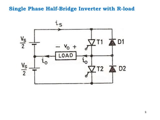
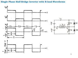
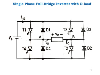
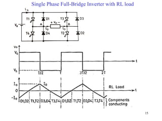
3. The main types of inverters are single phase half bridge, single phase full bridge, and three phase inverters, which produce different output voltage waveforms and can be powered by batteries or other DC sources.