Downloaded 26 times


The document discusses power electronics, focusing on phase-controlled converters that use controlled or semi-controlled switches like thyristors. It details the applications of these converters in various industries, their types (uncontrolled, half-controlled, and fully controlled), and the analysis of single-phase and three-phase configurations. Additionally, it explains the effects of source inductance on performance and introduces dual converters for four quadrant operation in motor control.
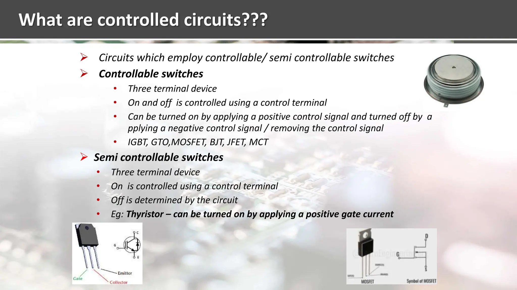
Overview of power electronics, focus on phase-controlled converters and types of controlled circuits.
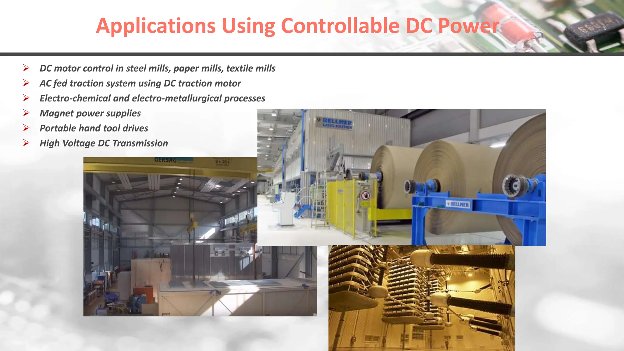
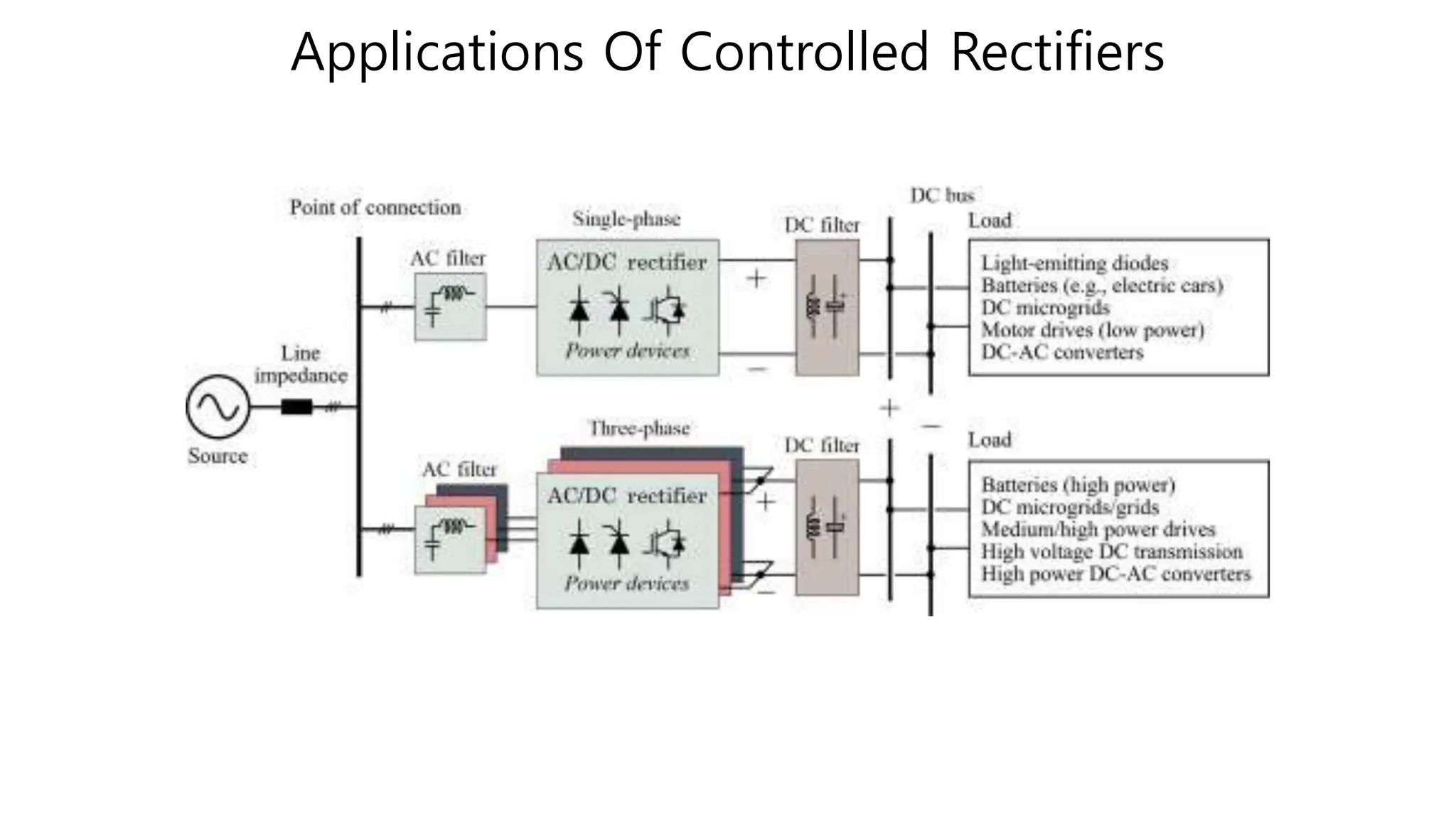
Discusses the applications of controllable DC power in various industries such as steel and textile, and systems like high voltage DC transmission.
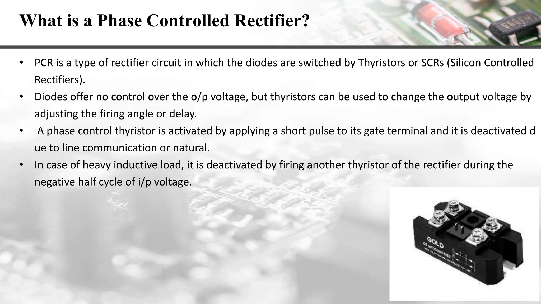
Explains the role of thyristors in AC to DC conversion, focusing on phase-controlled rectifiers and their operation.
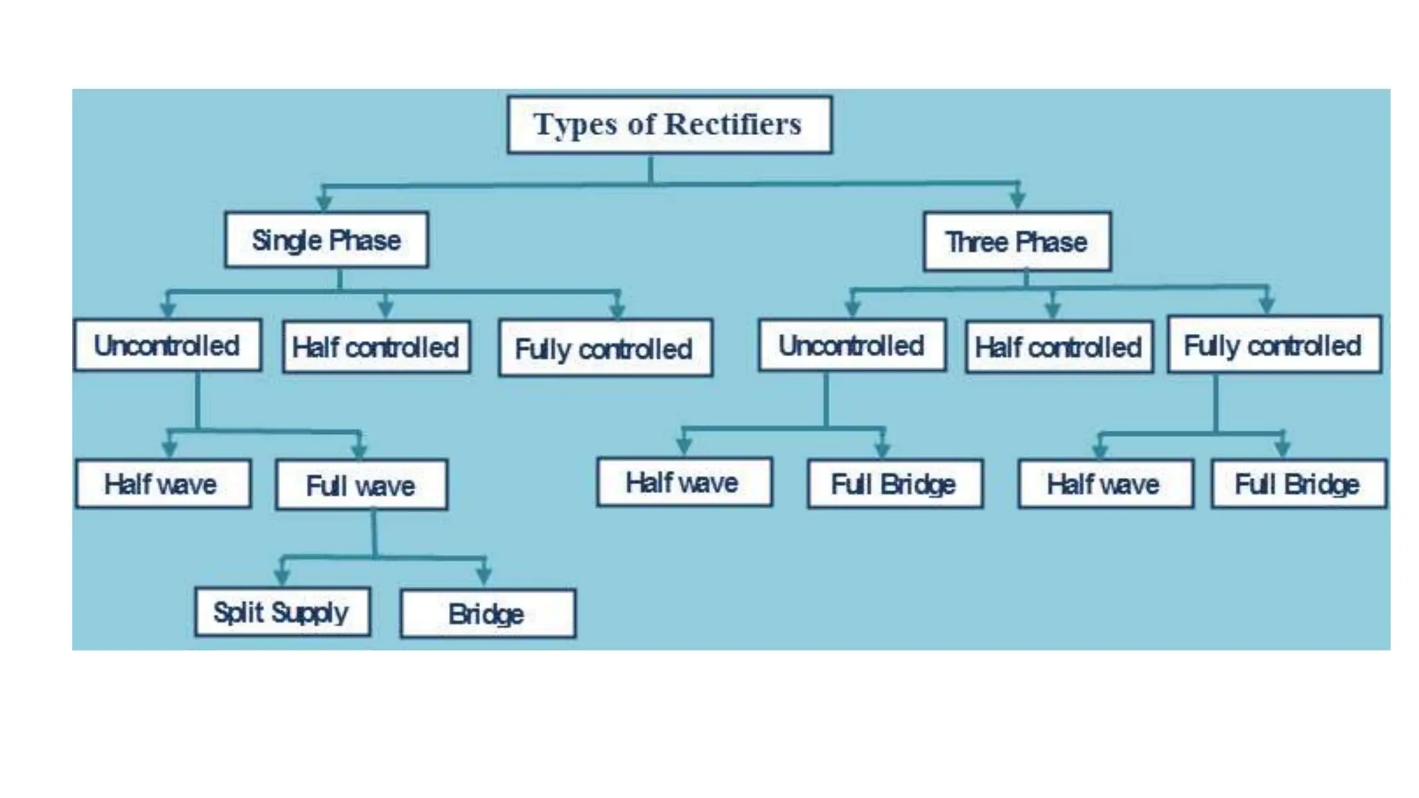
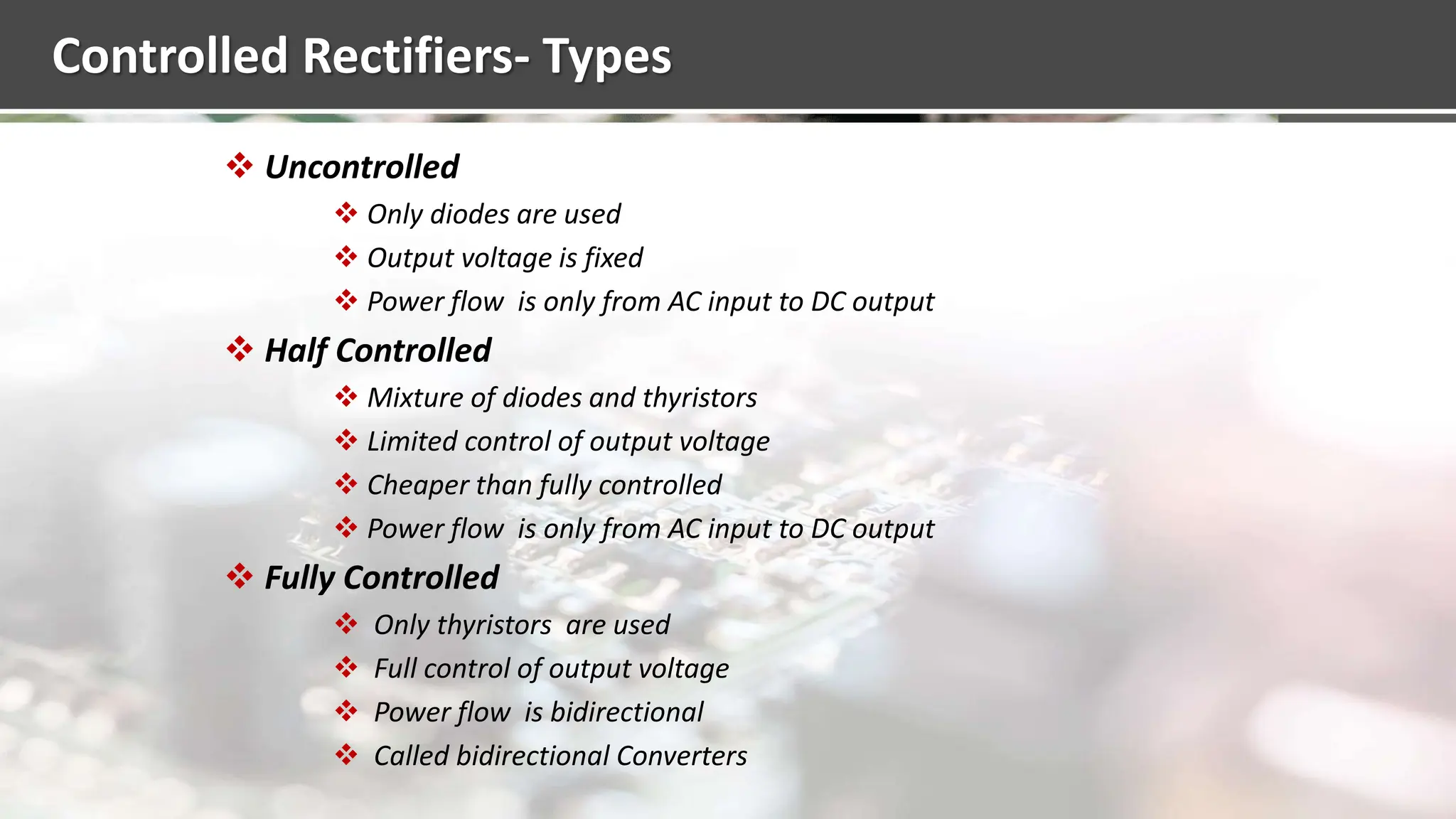
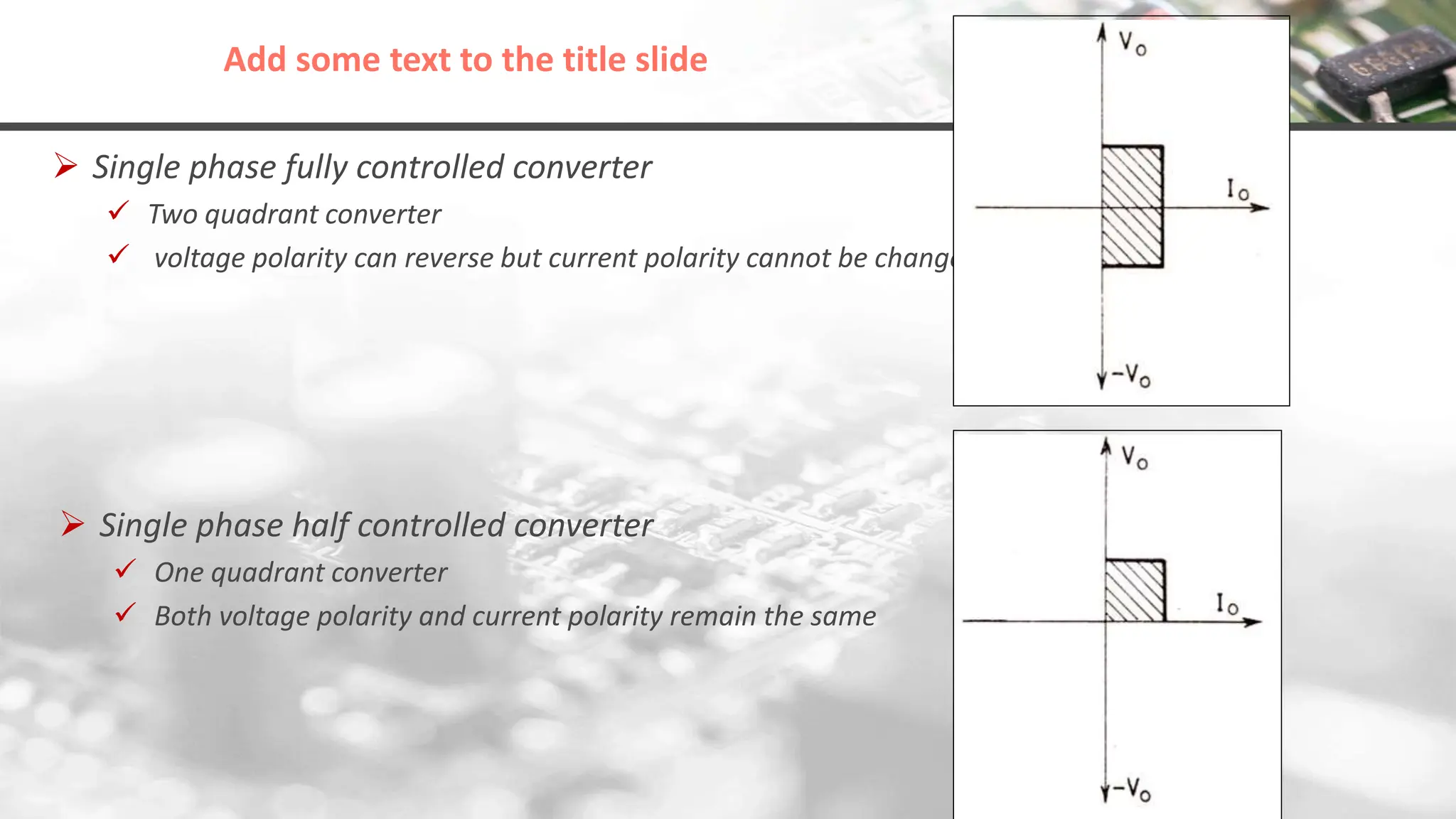
Describes different types of controlled rectifiers: uncontrolled, half-controlled, fully controlled, and specific modes like half wave and full wave.
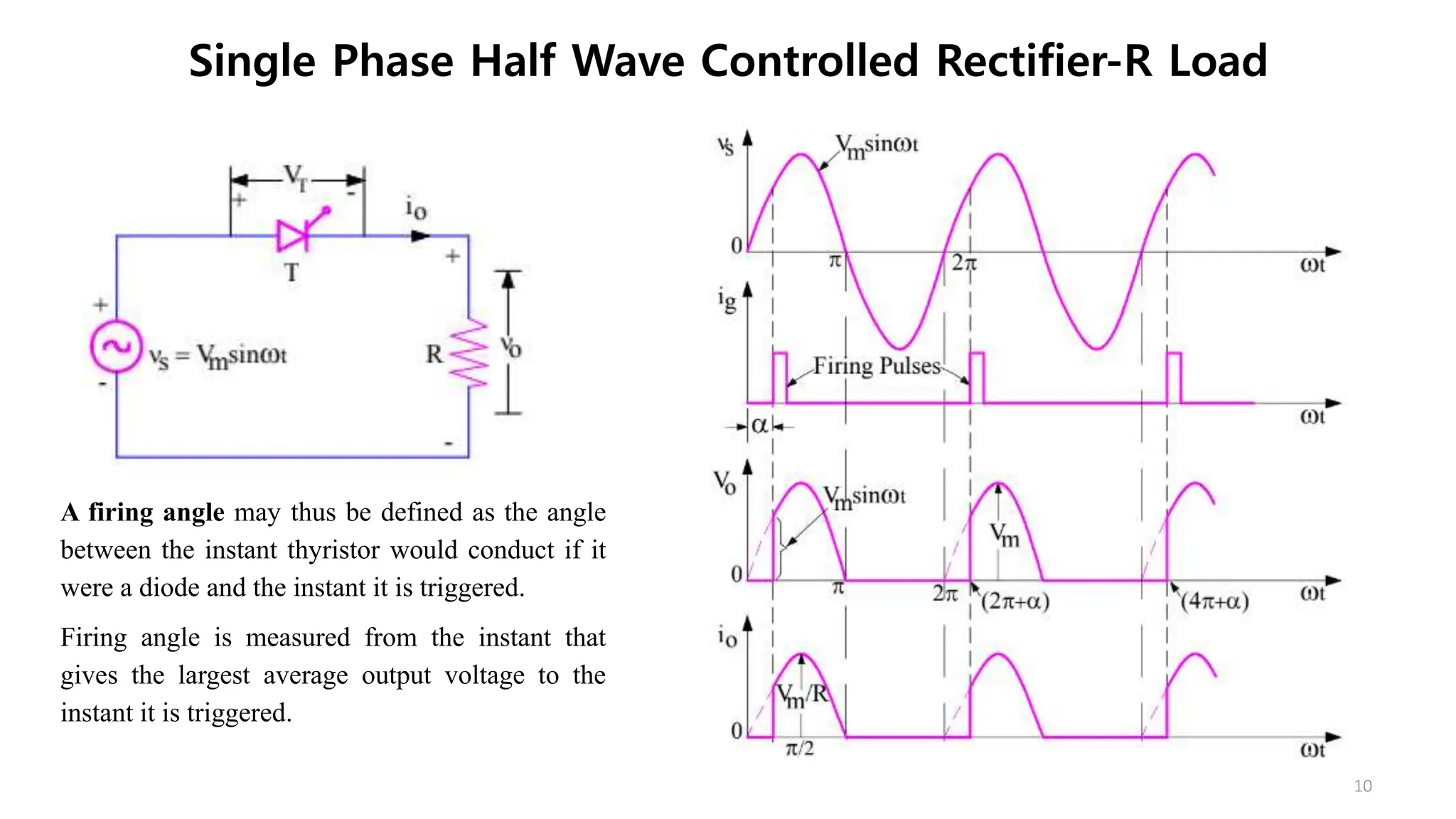
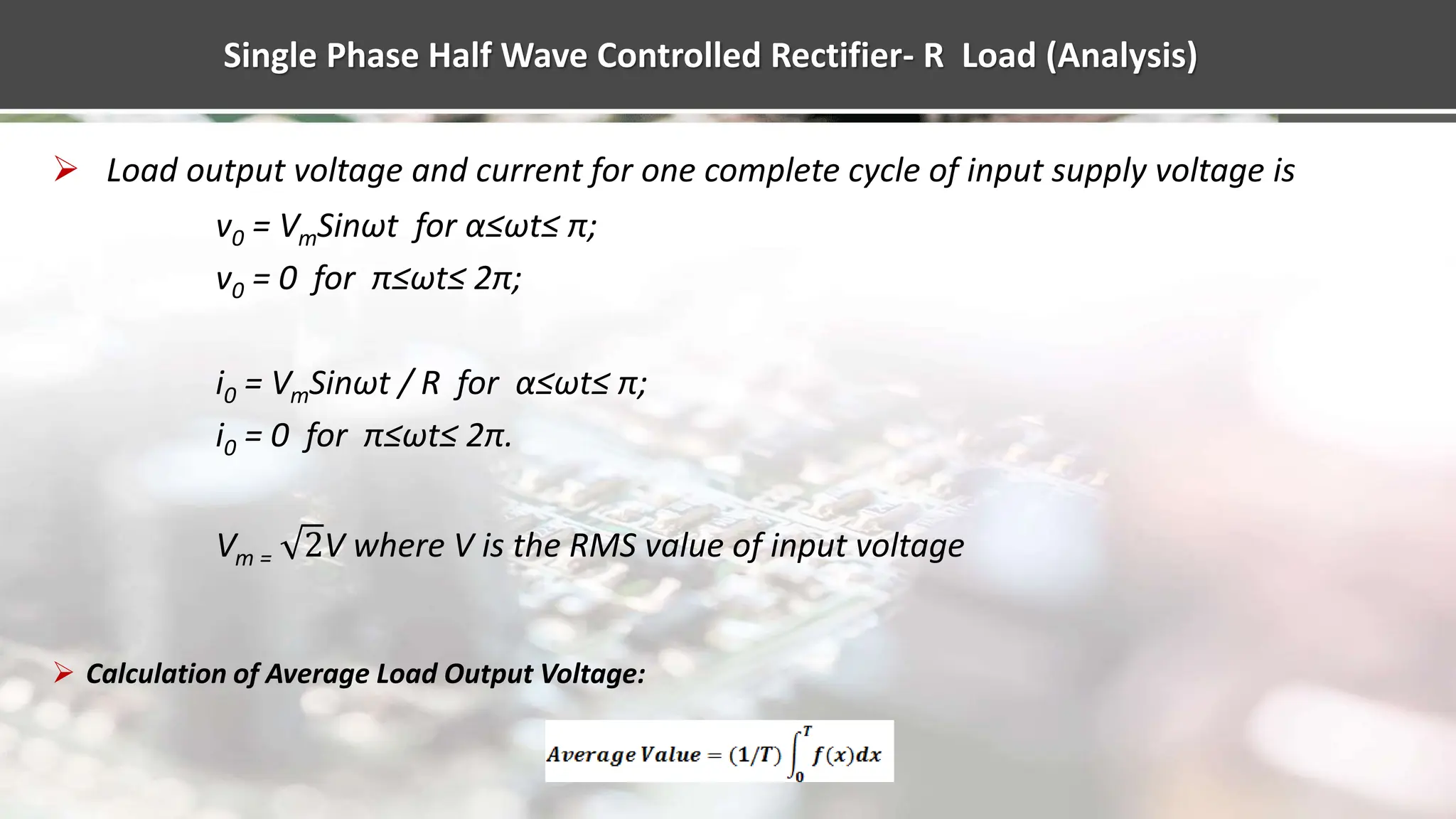
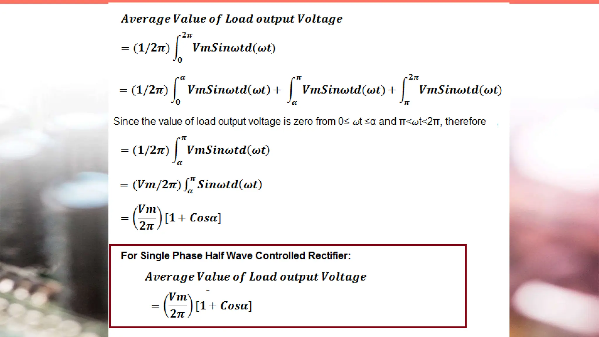
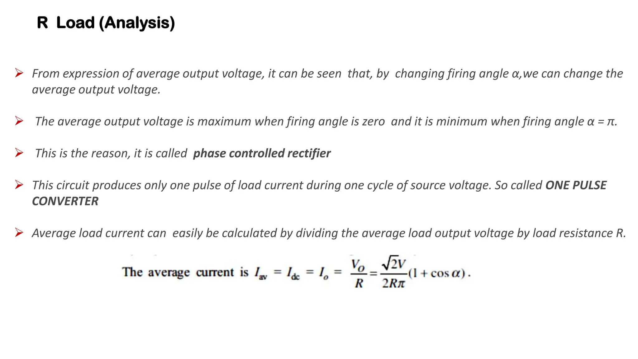
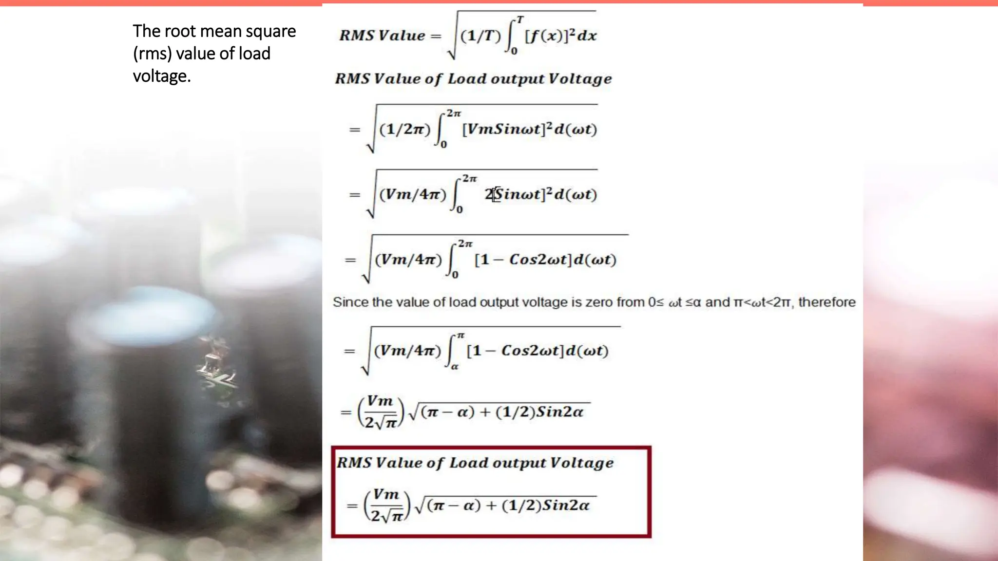
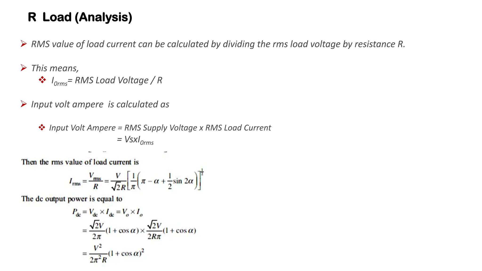
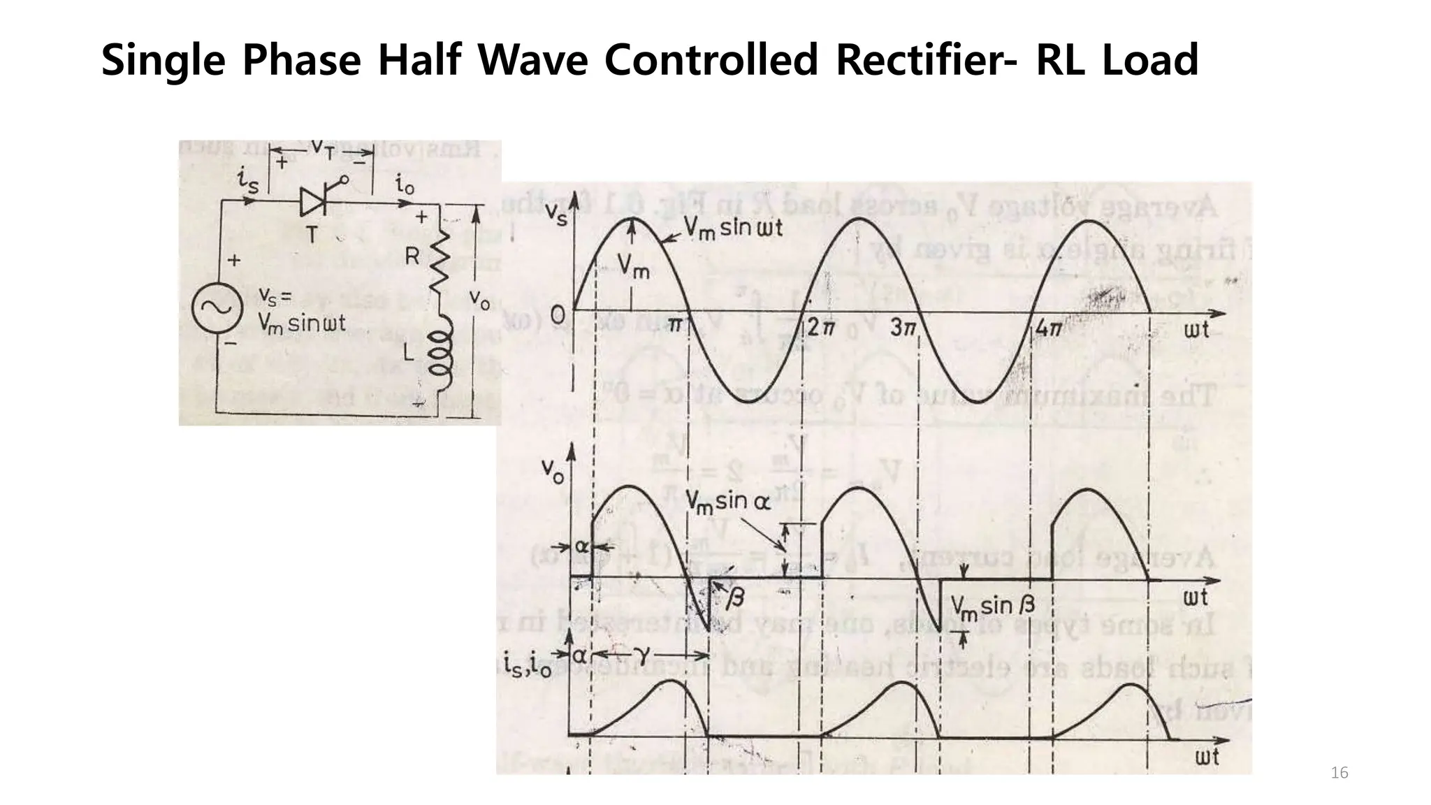
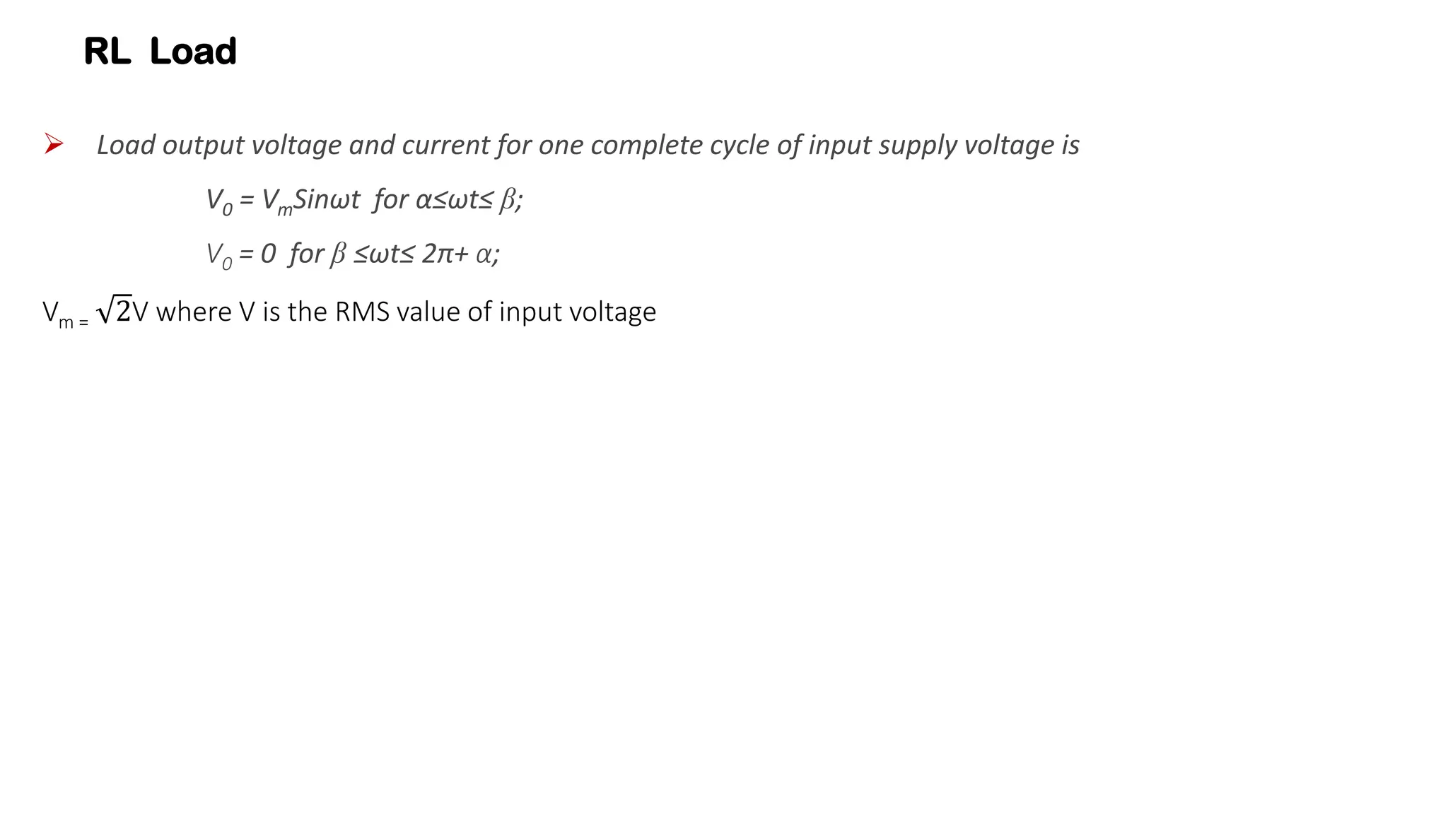
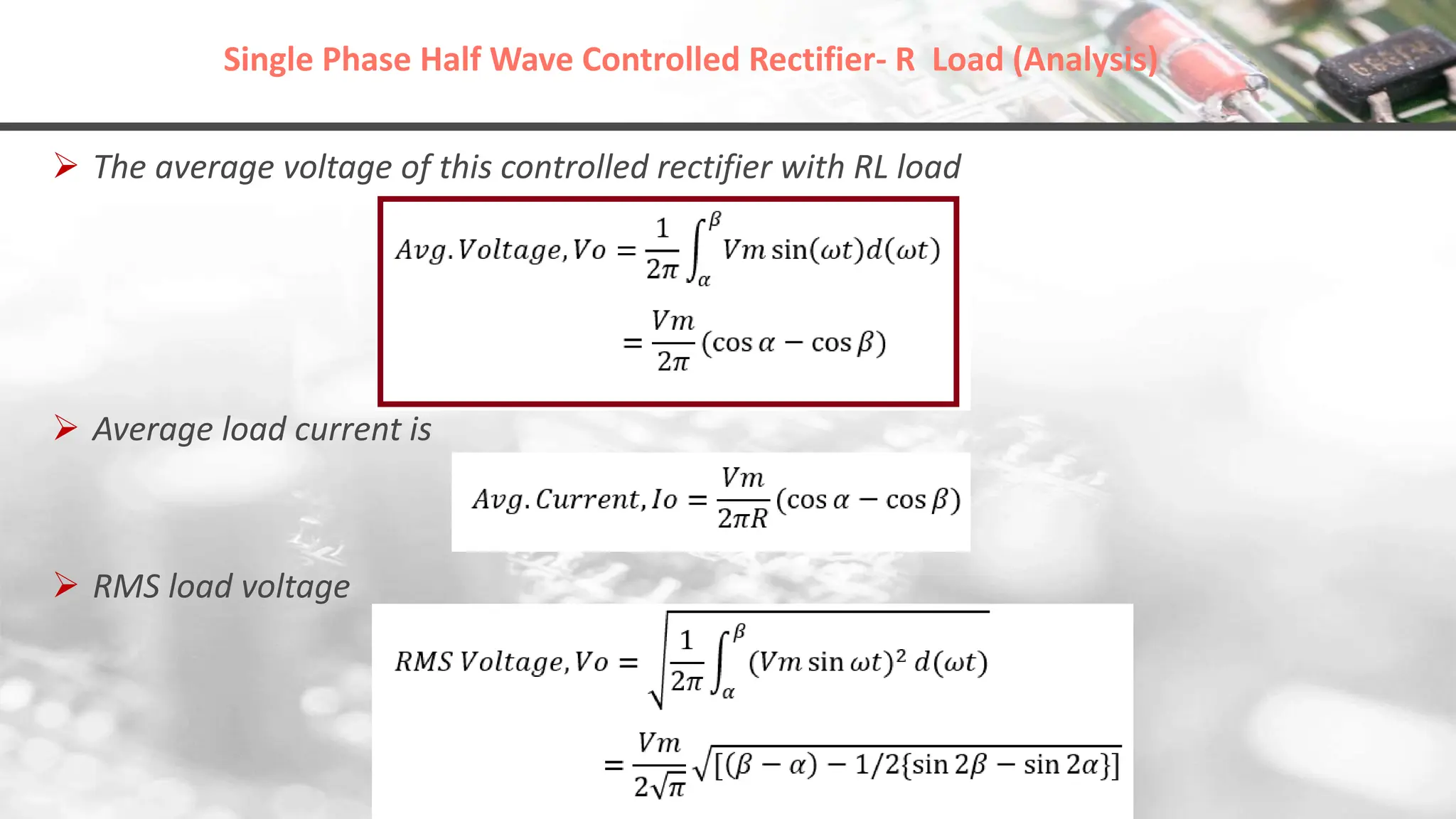
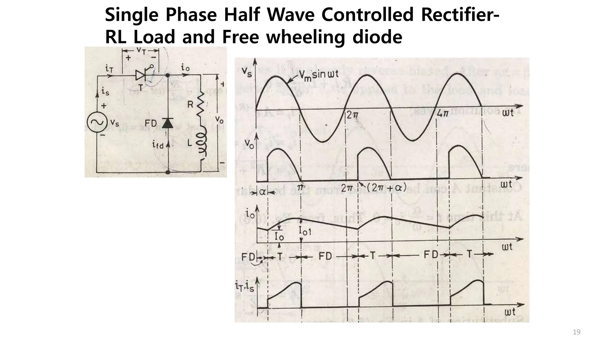
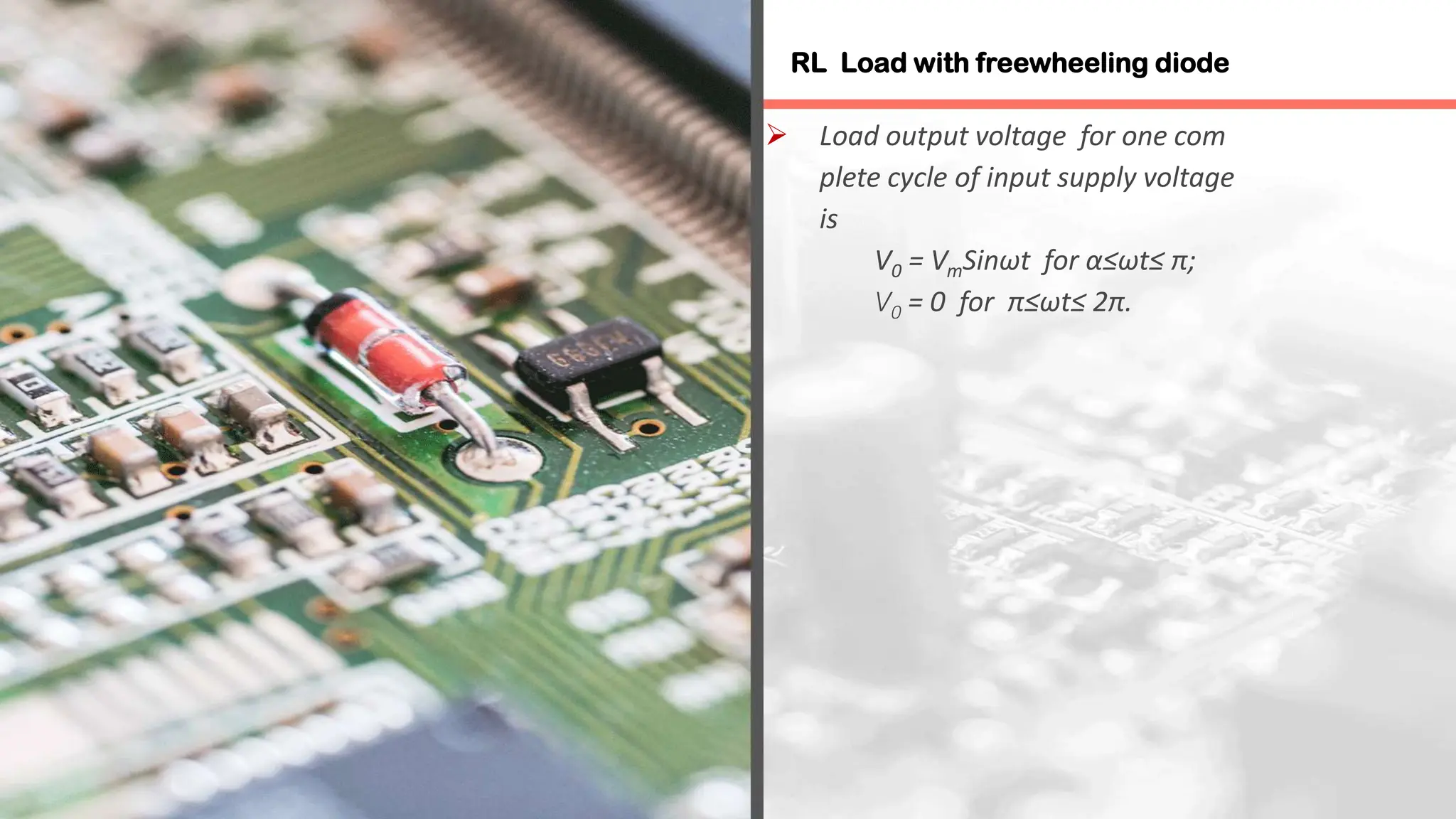
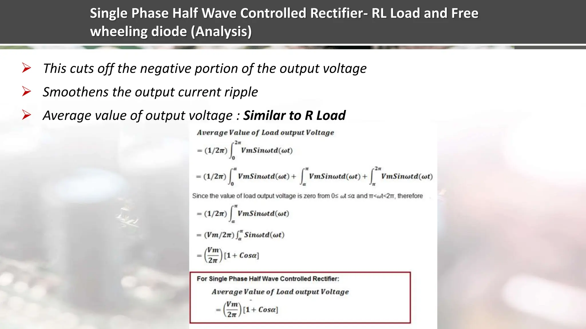
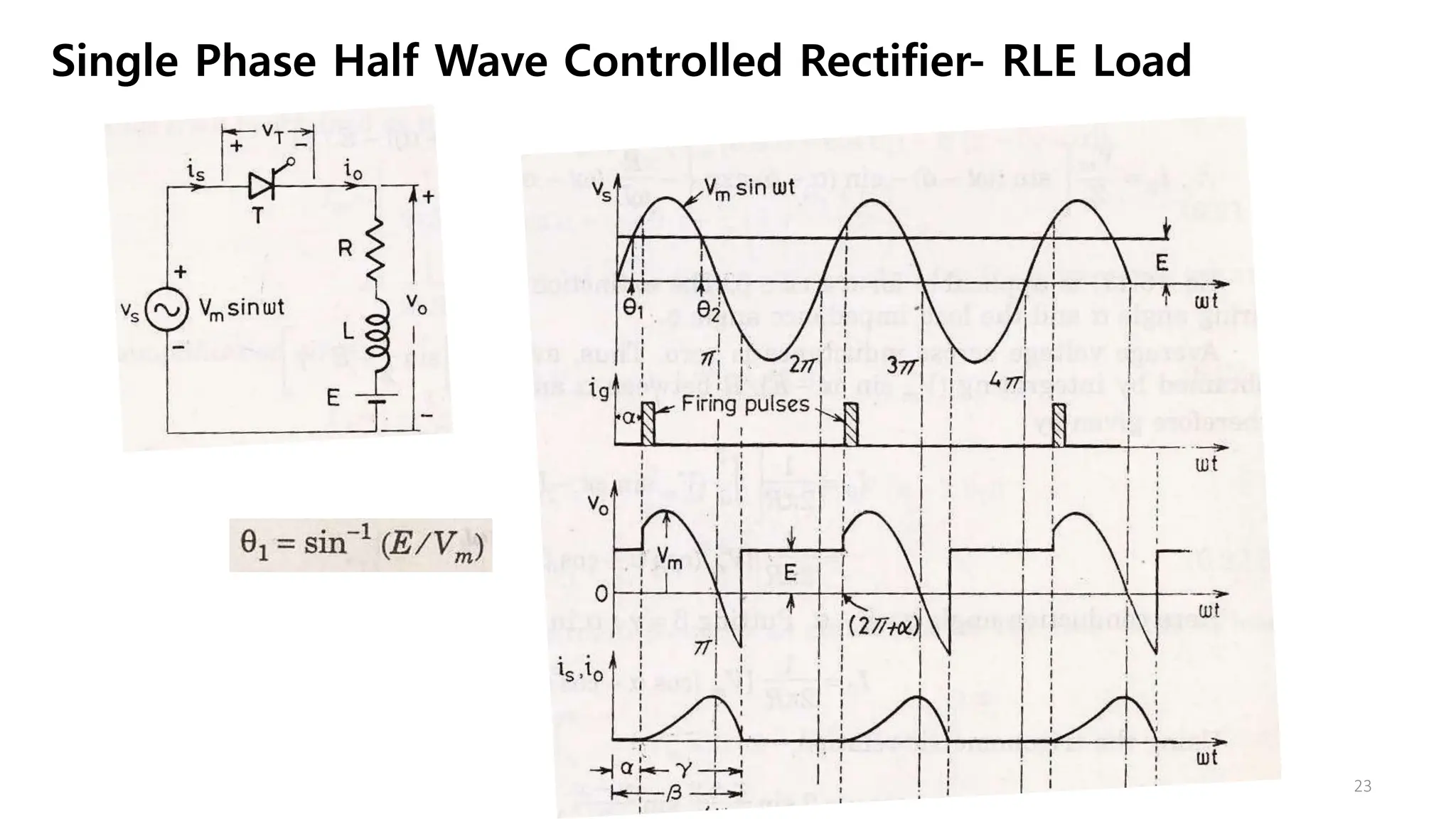
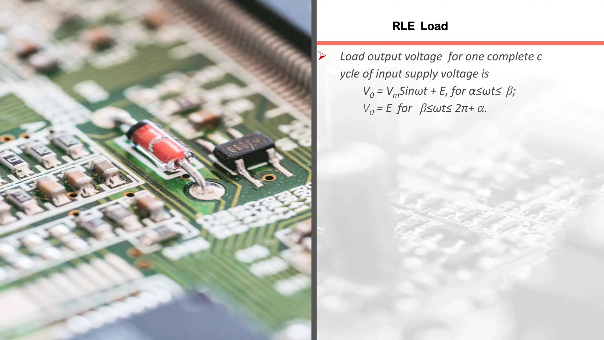
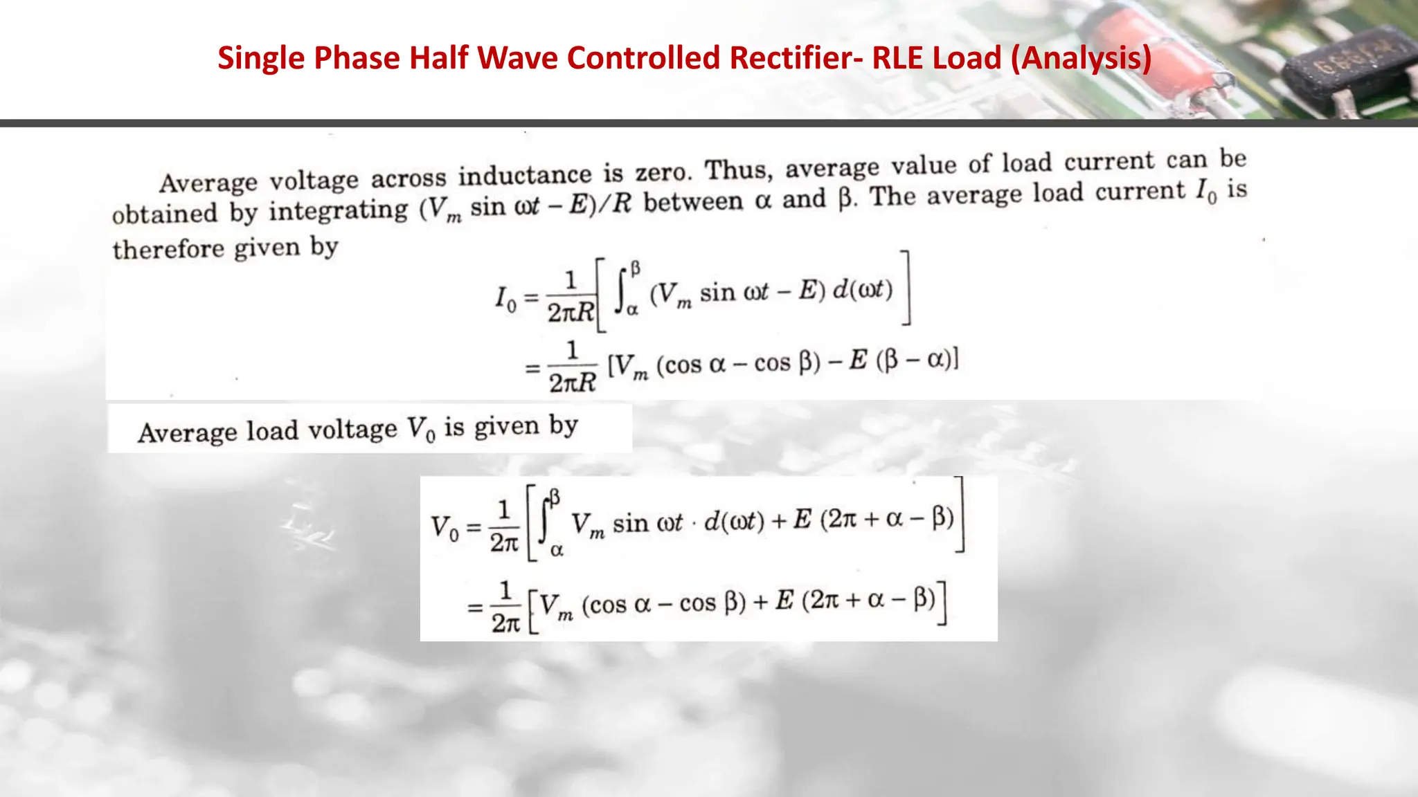
Details the analysis of single-phase half wave controlled rectifiers under different load conditions, emphasizing firing angles and voltage current relationships.
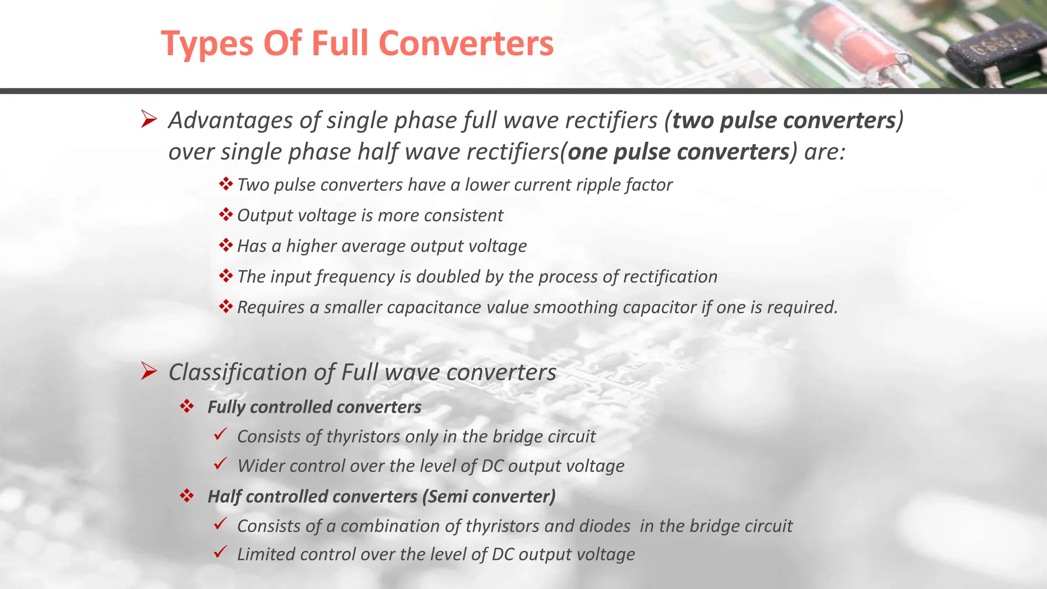
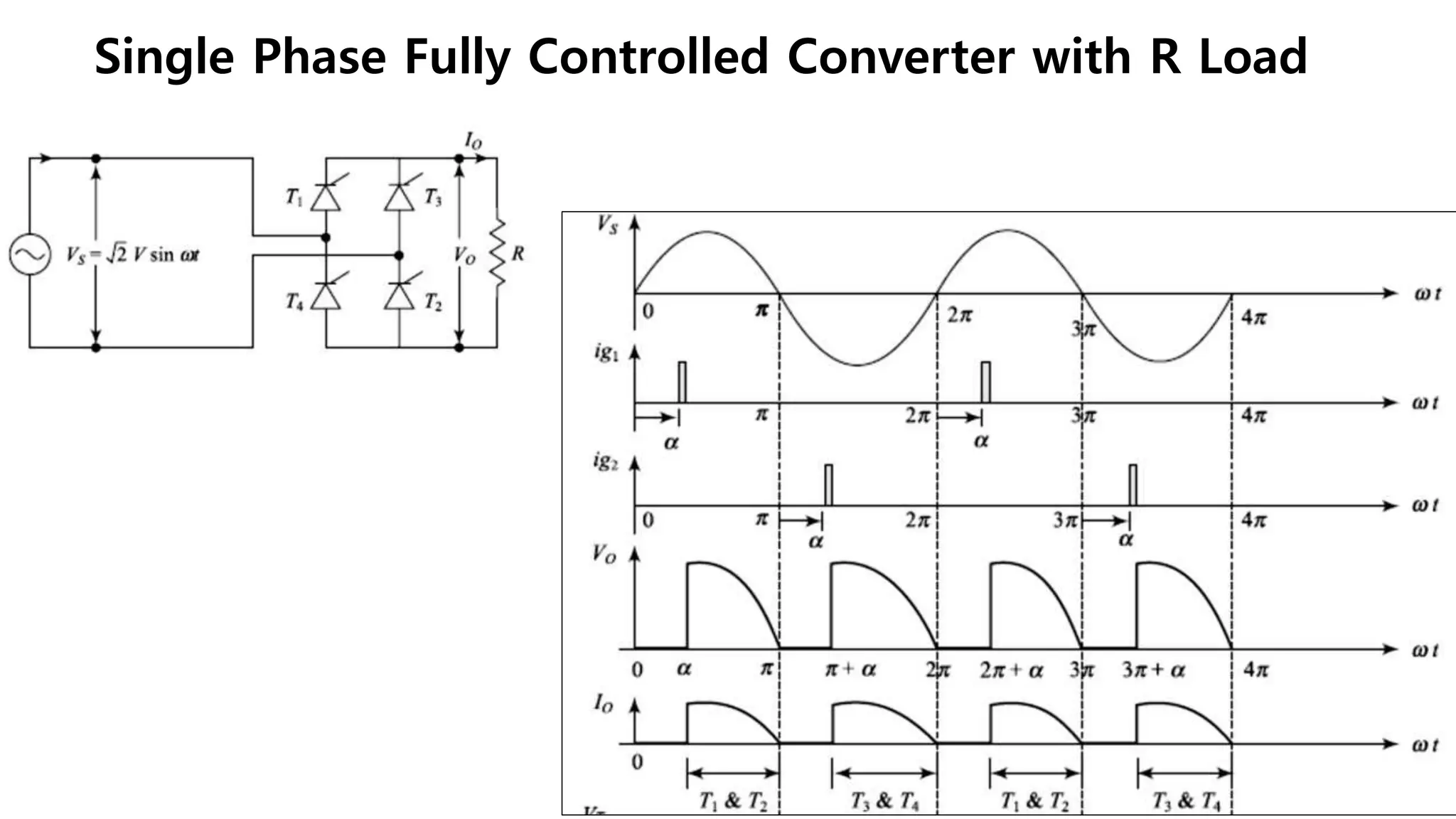
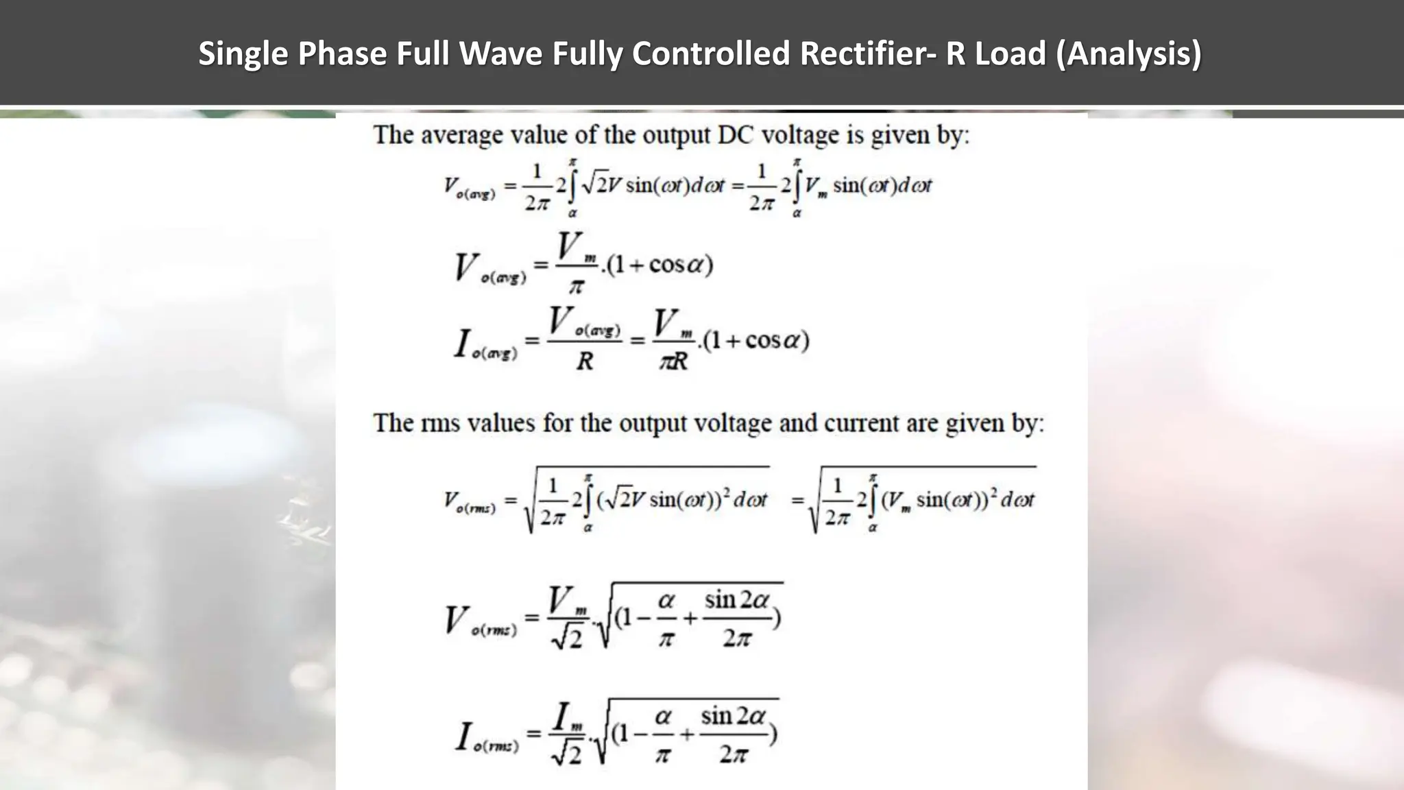
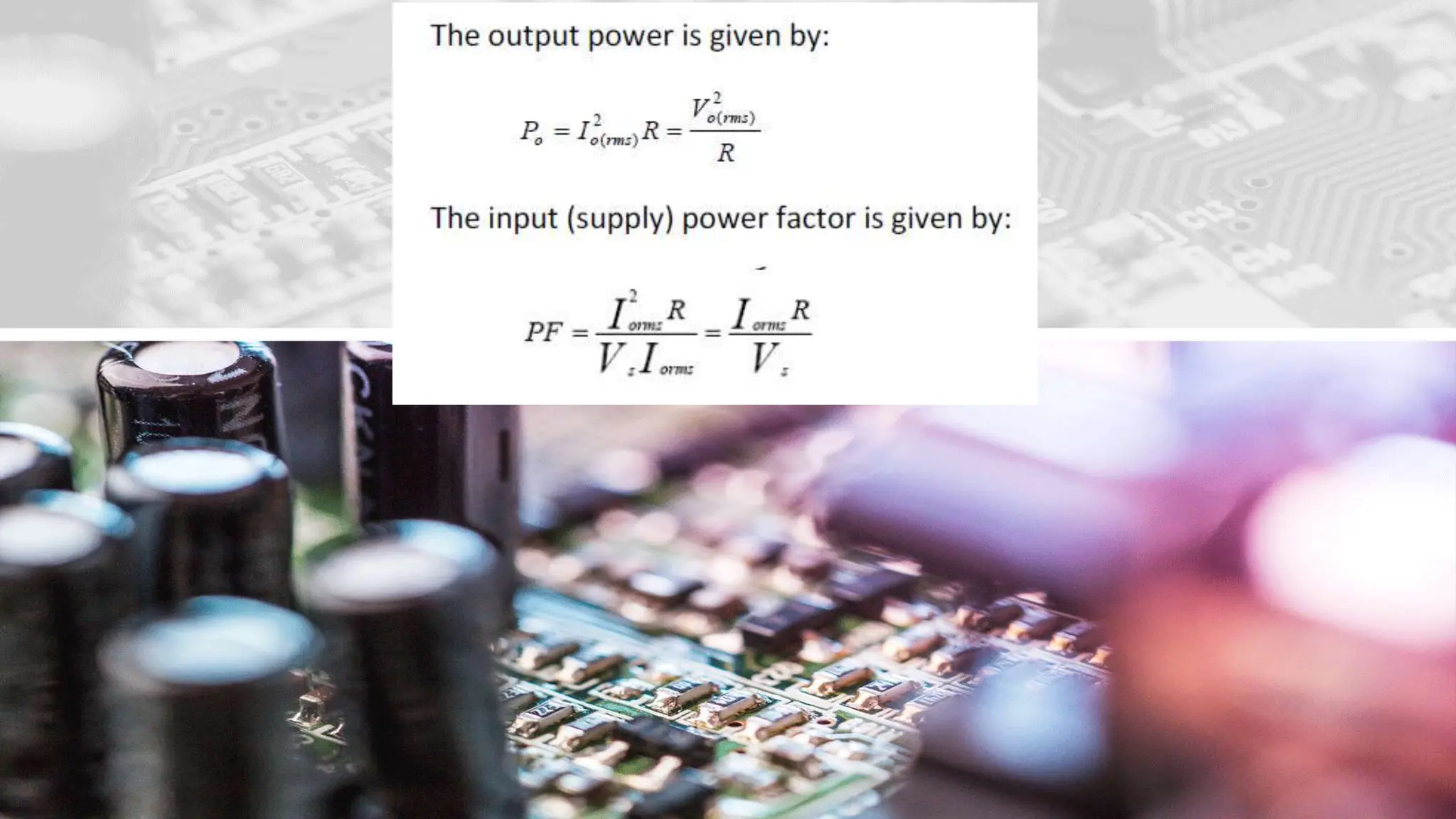
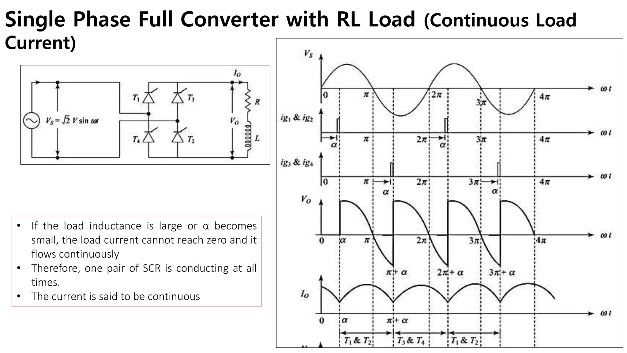
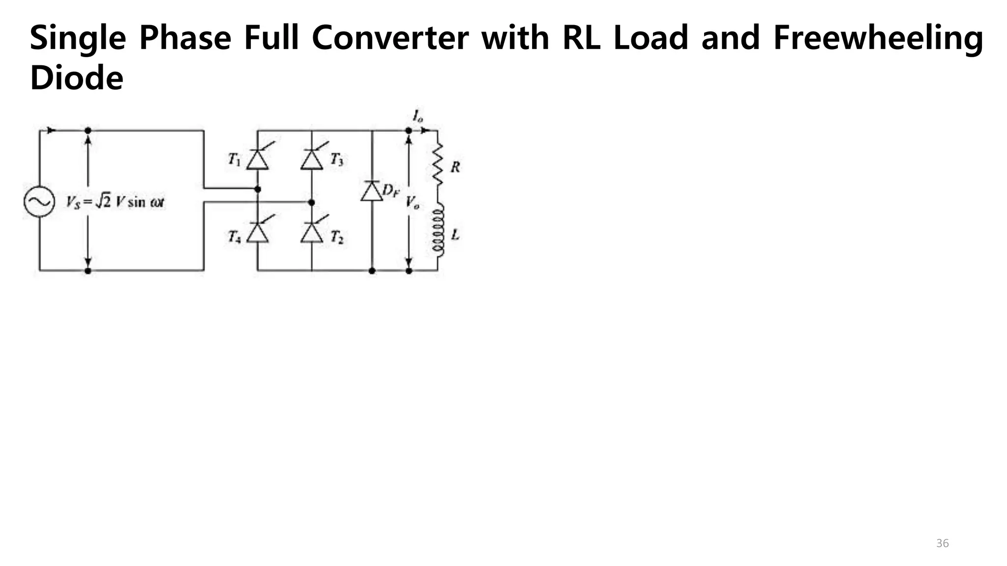
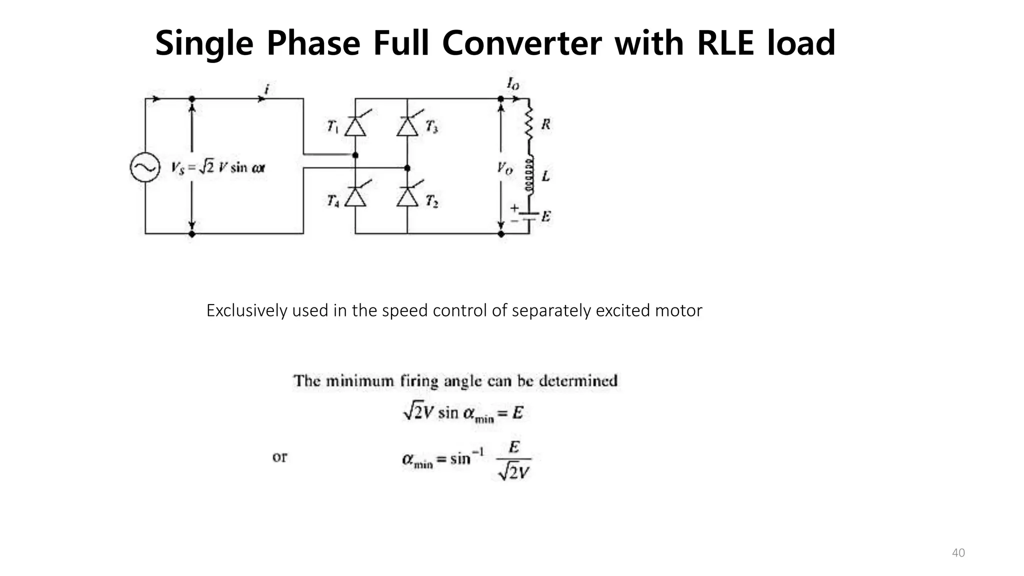
Introduces applications of controlled rectifiers and discusses single-phase full wave converters and their advantages.
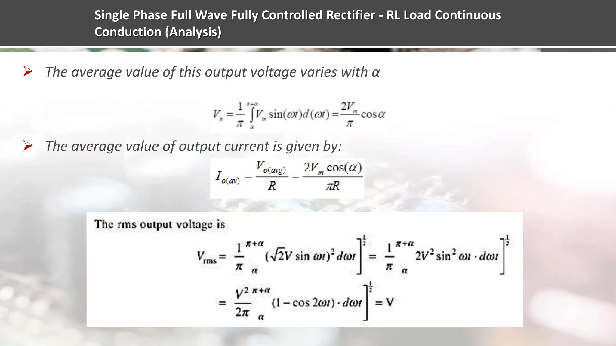
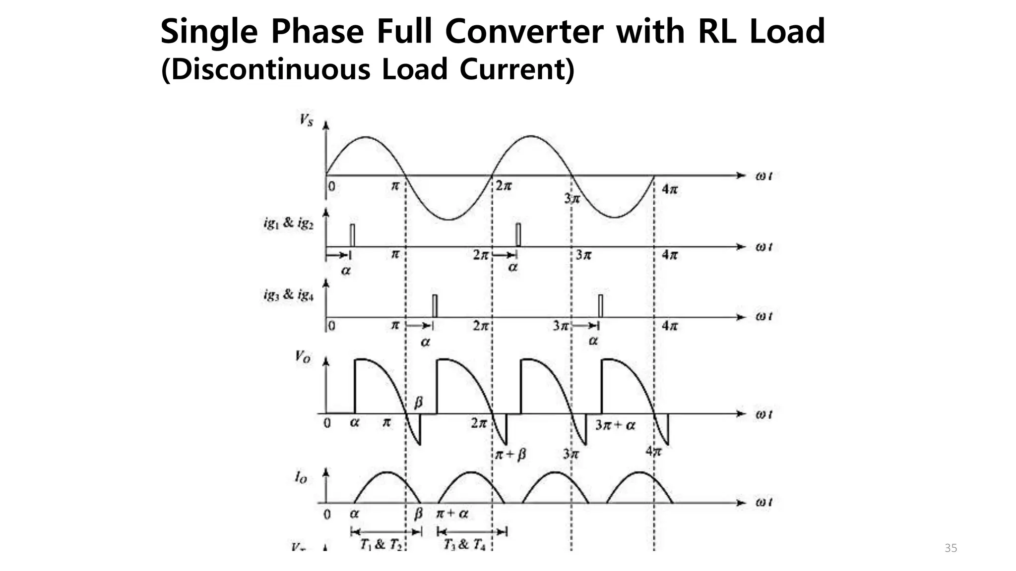
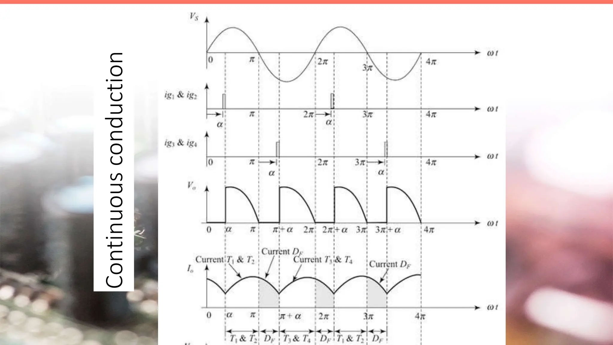
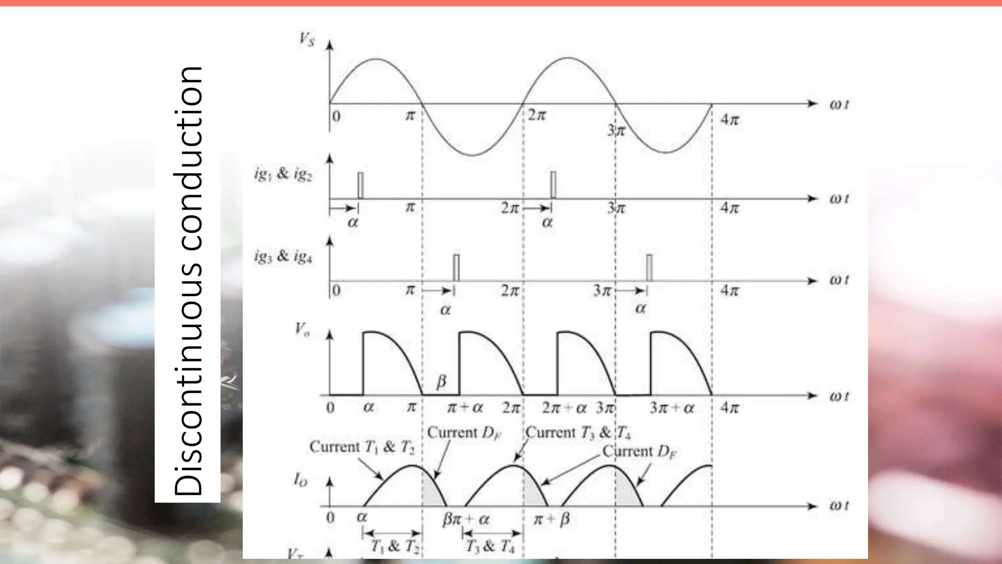
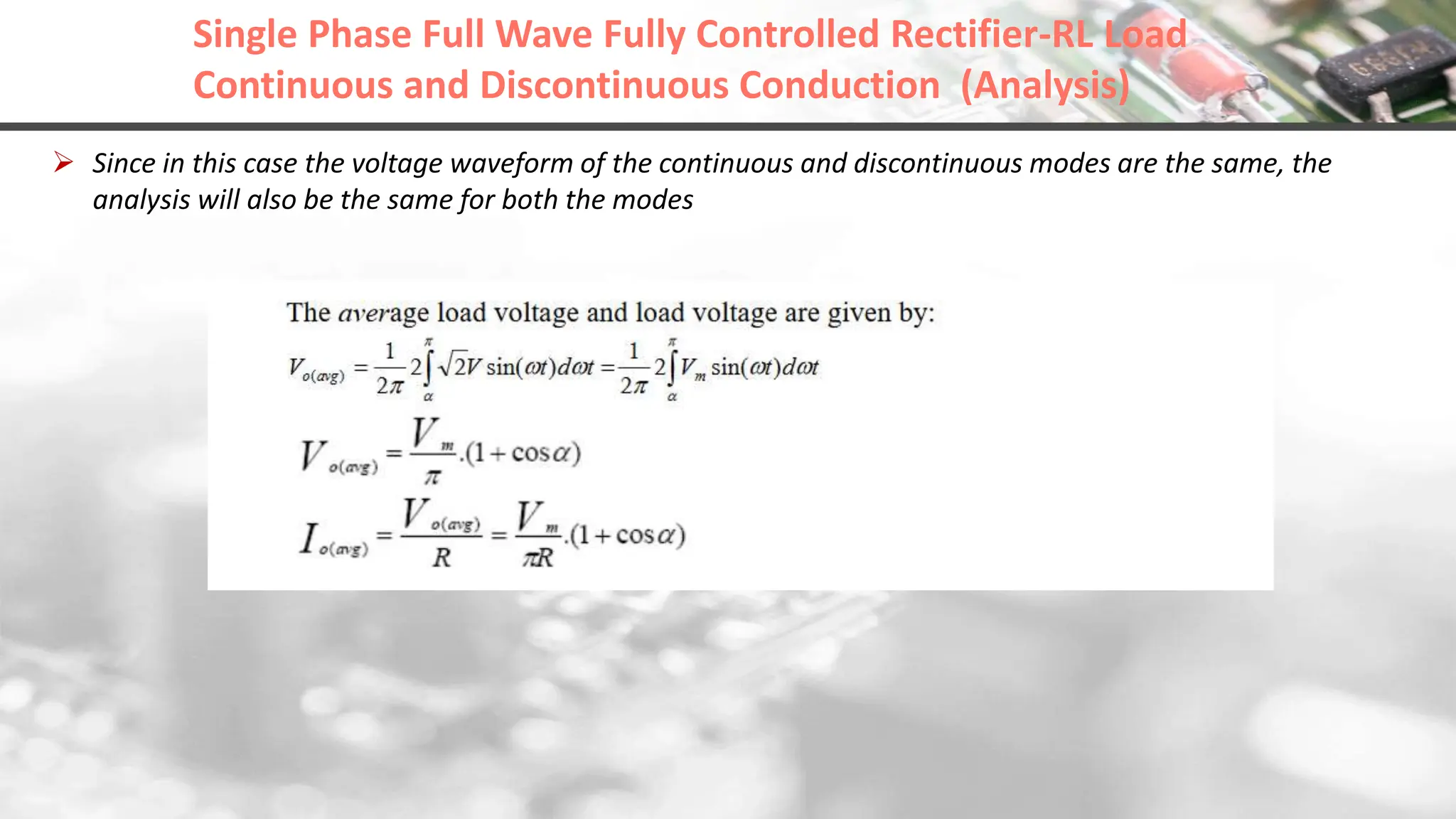
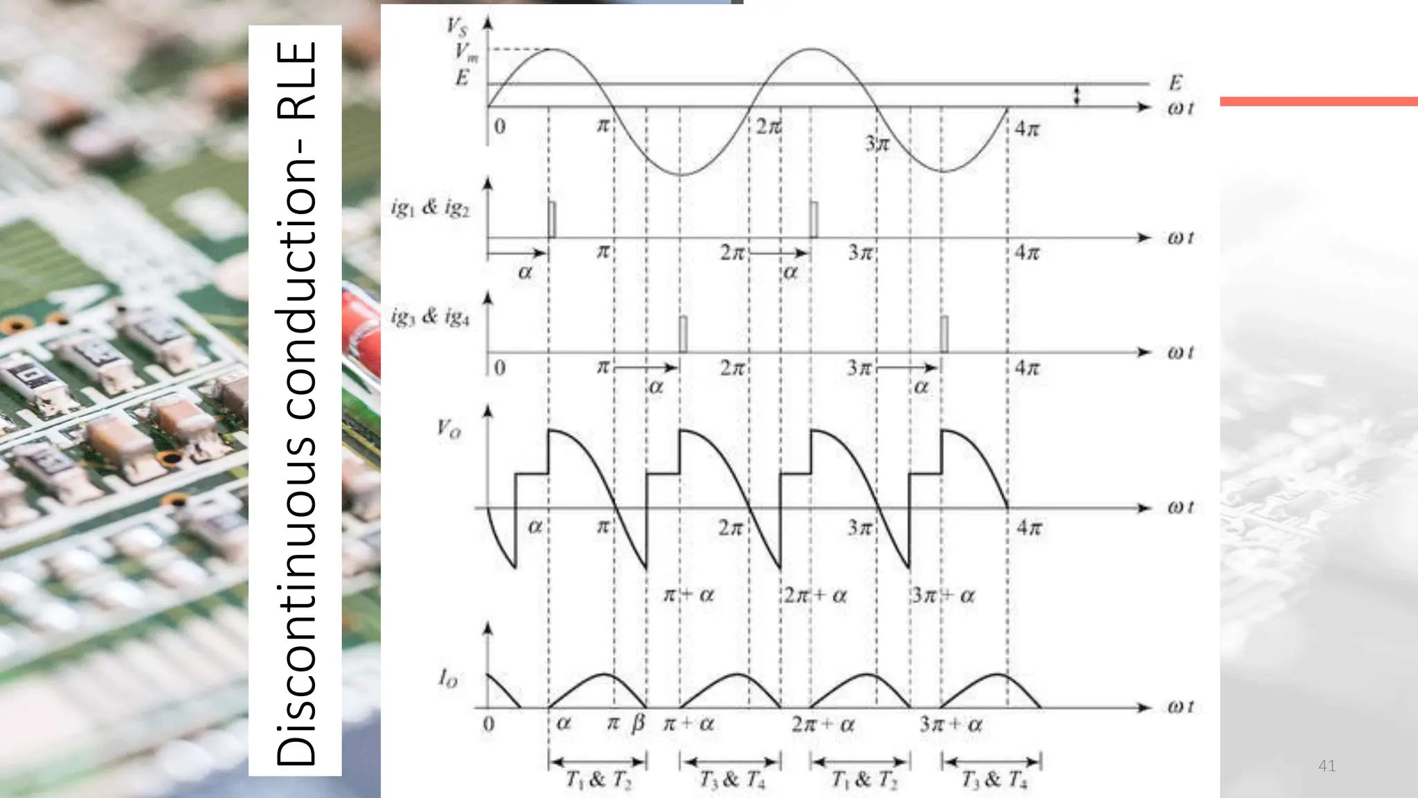
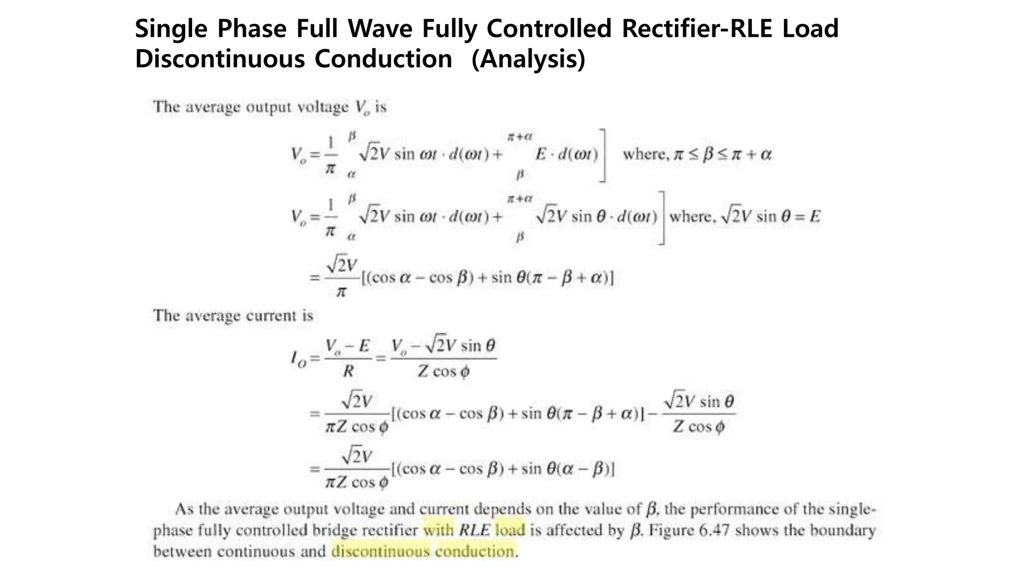
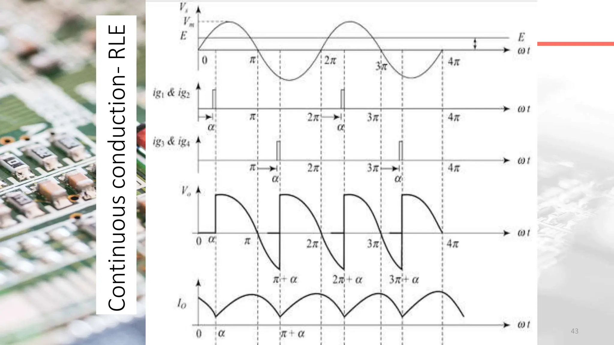
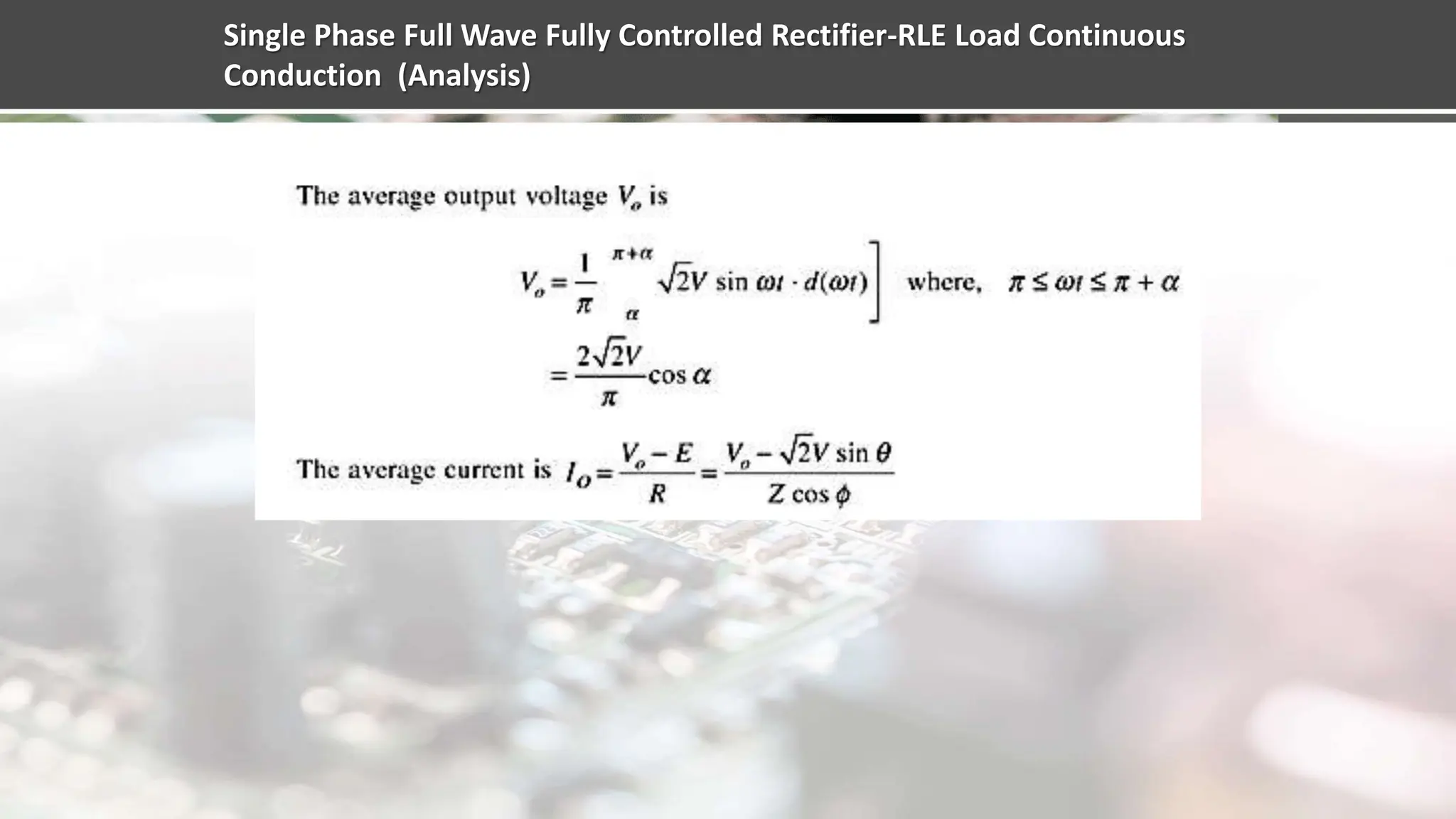
Explains continuous and discontinuous conduction in full wave converters, particularly with RL and RLE loads.
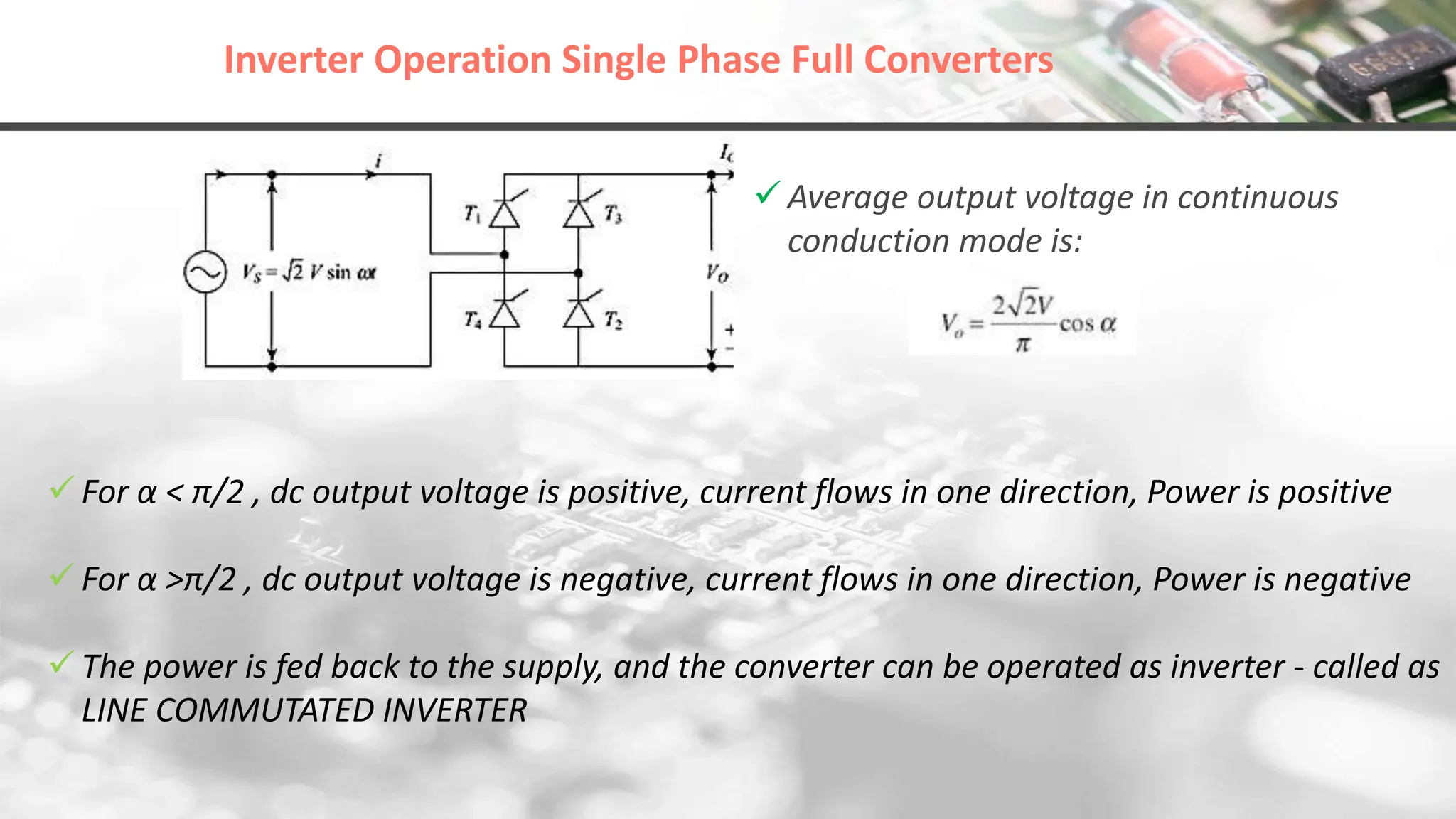
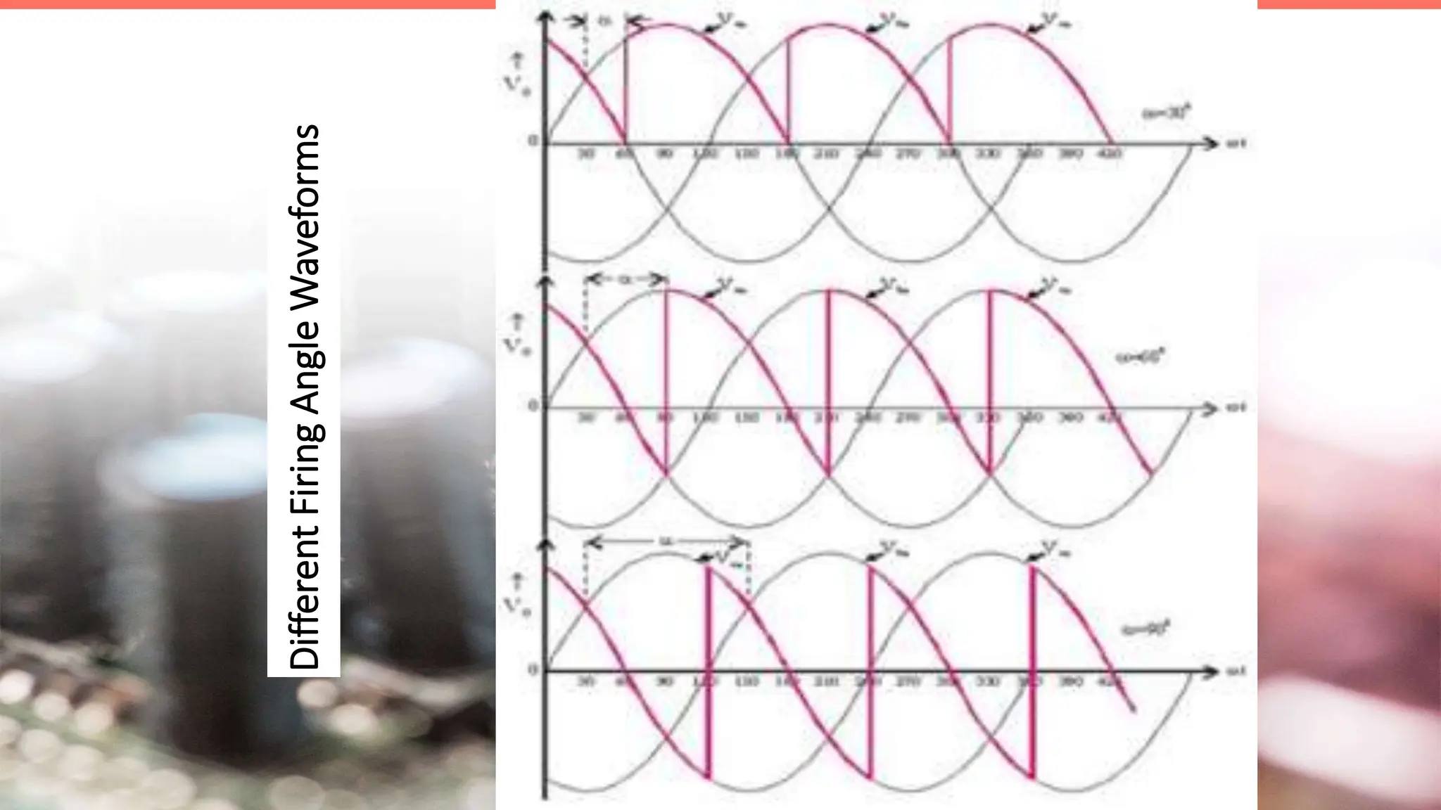
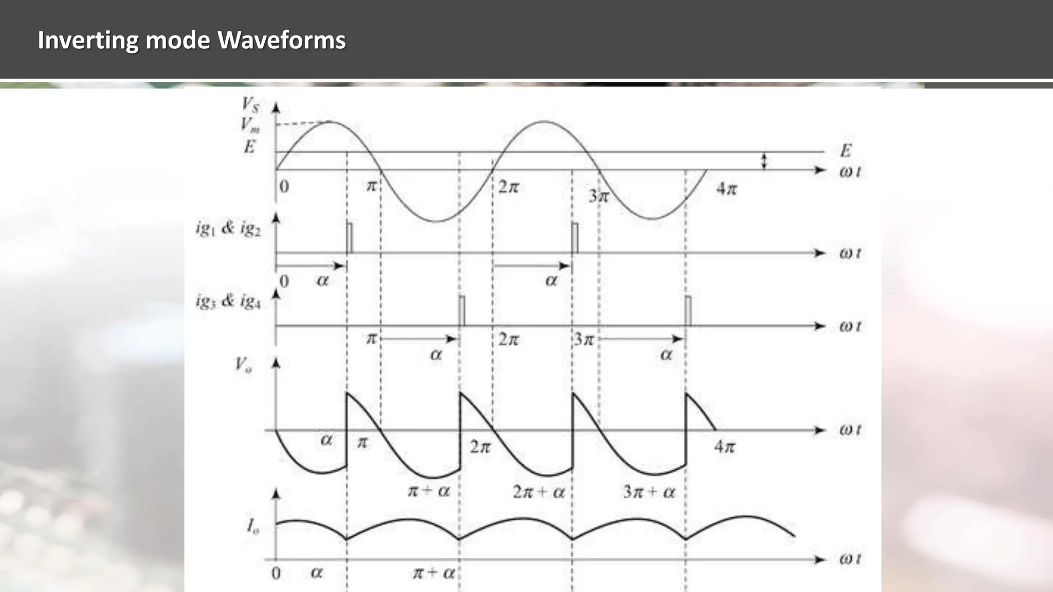
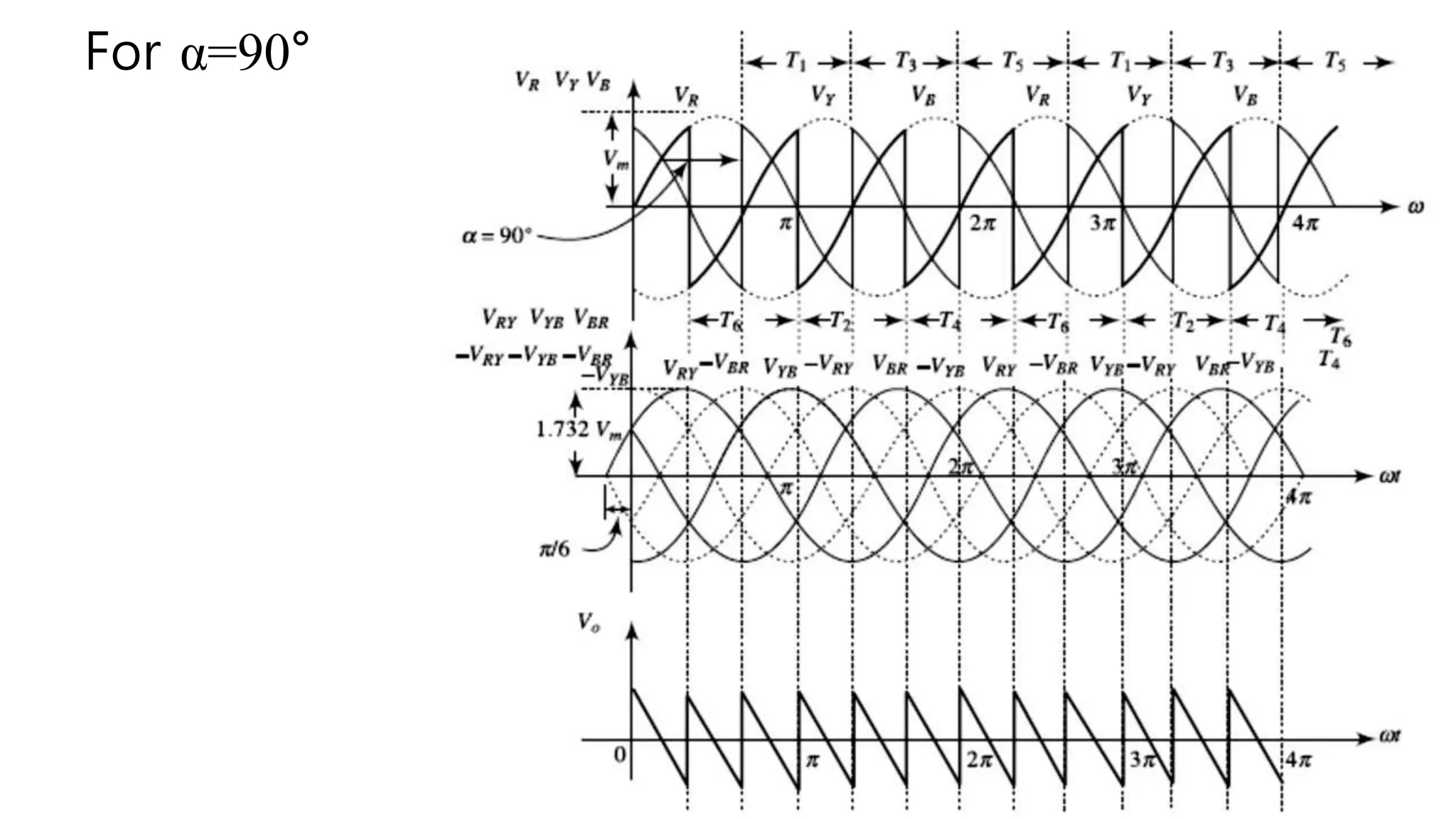
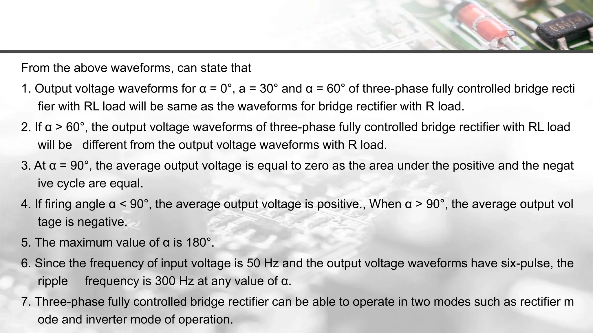
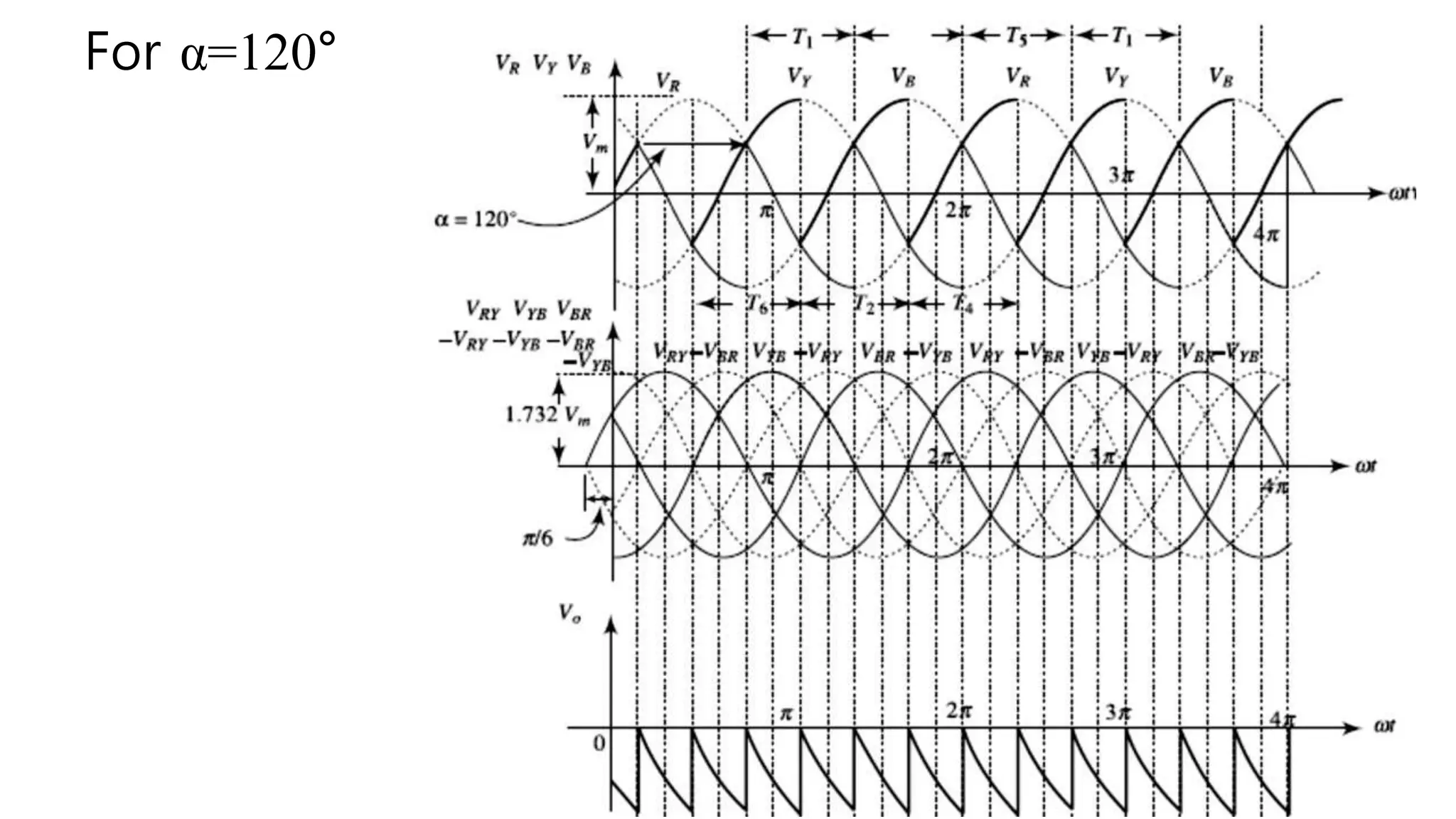
Discusses the inverter operation in full converters based on firing angle variations and respective output voltages.
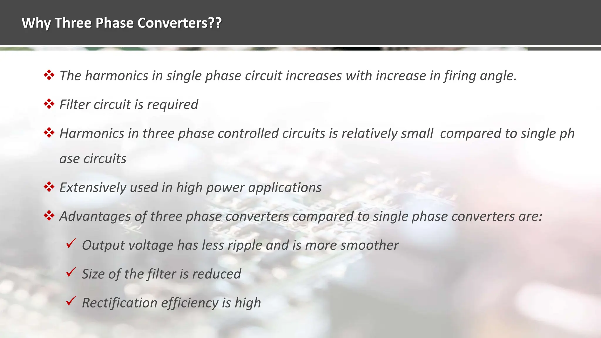
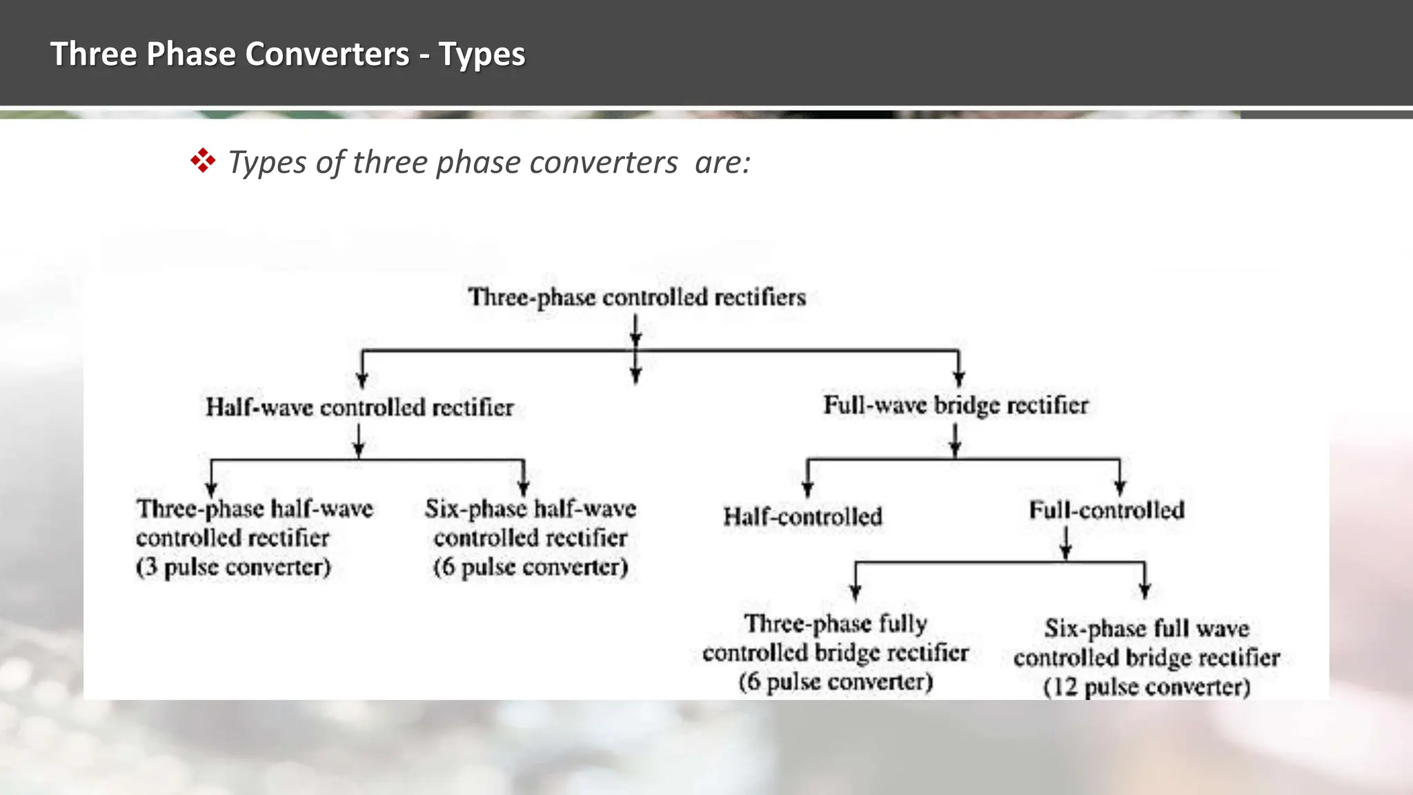
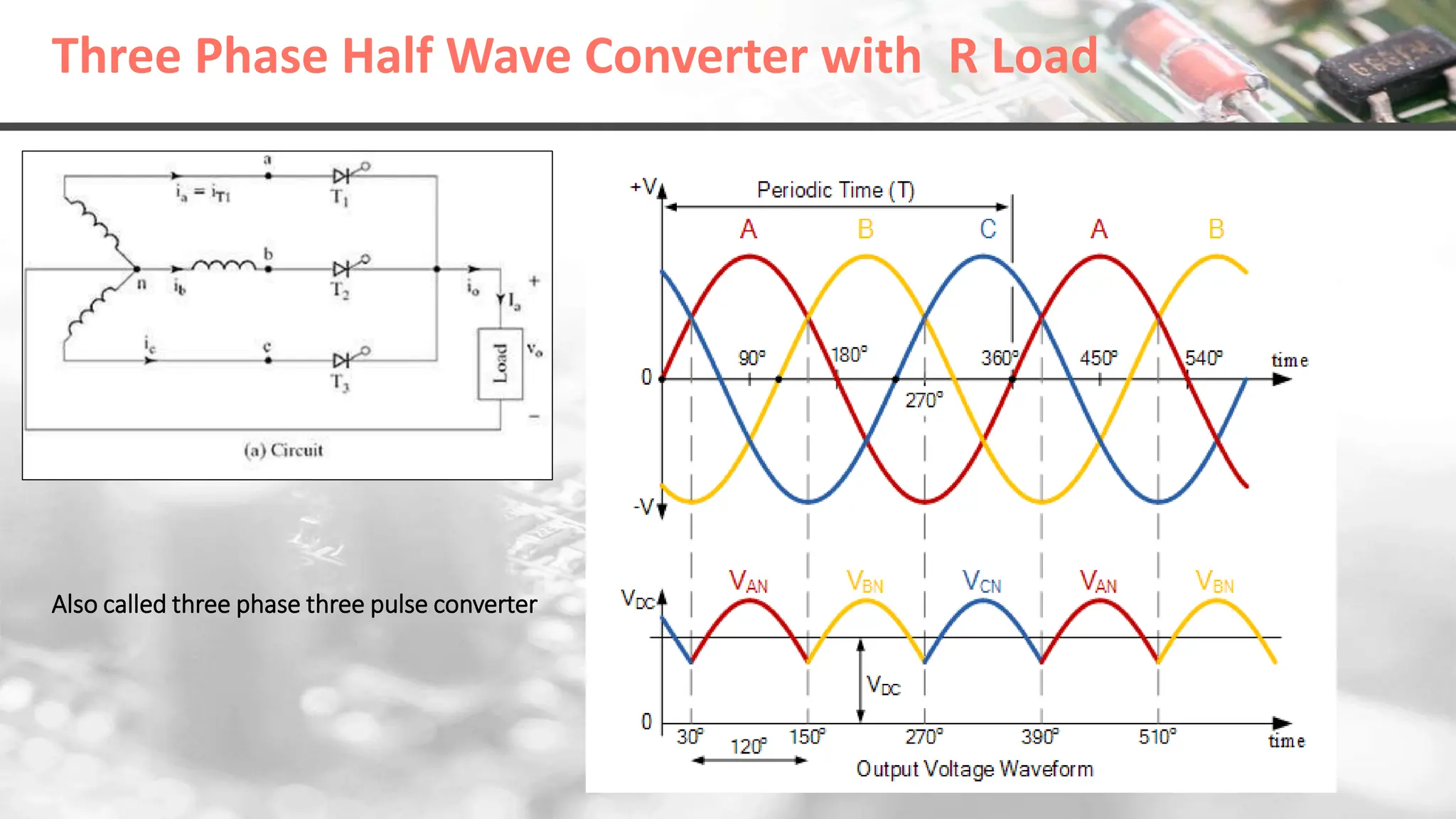
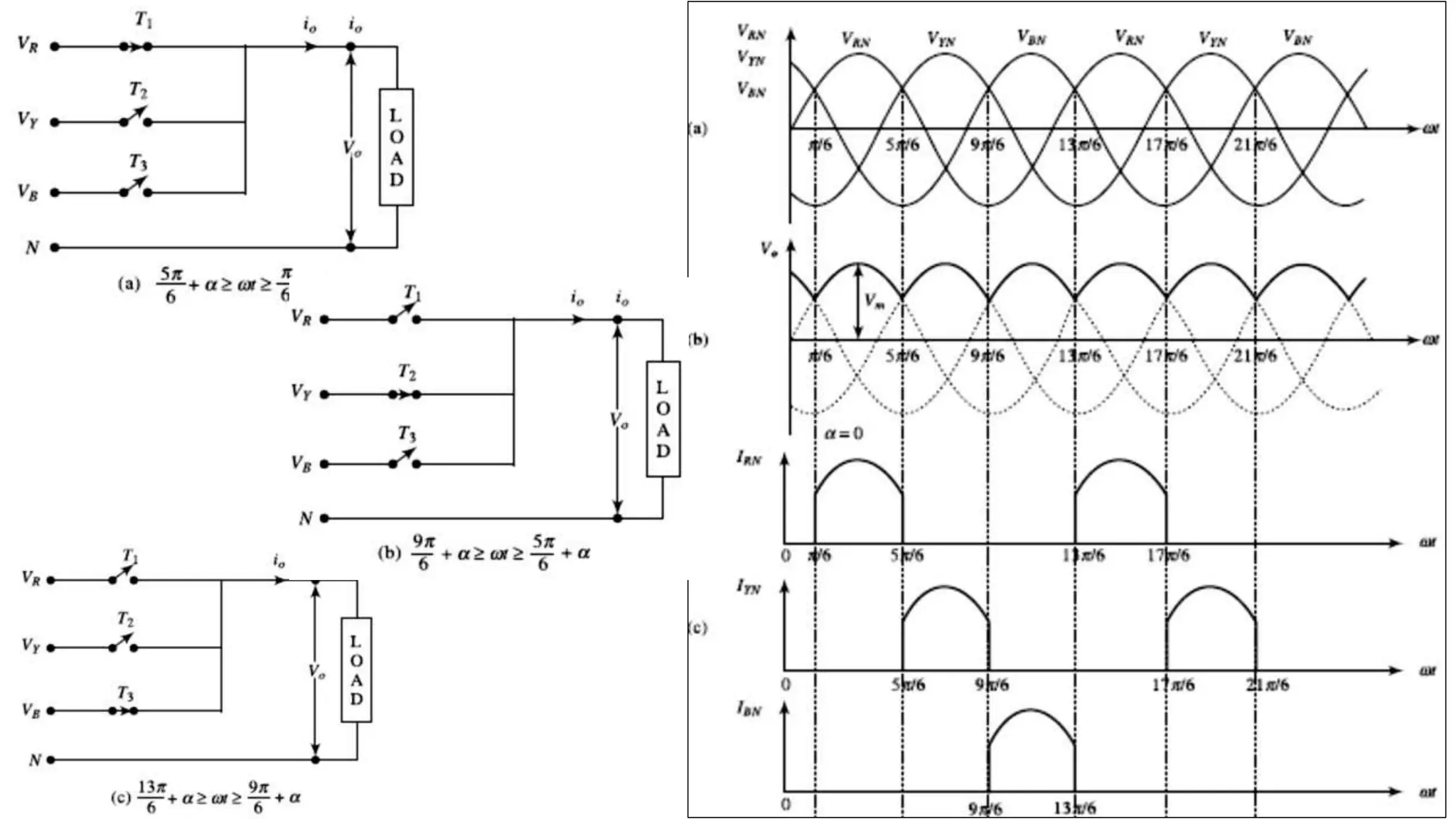
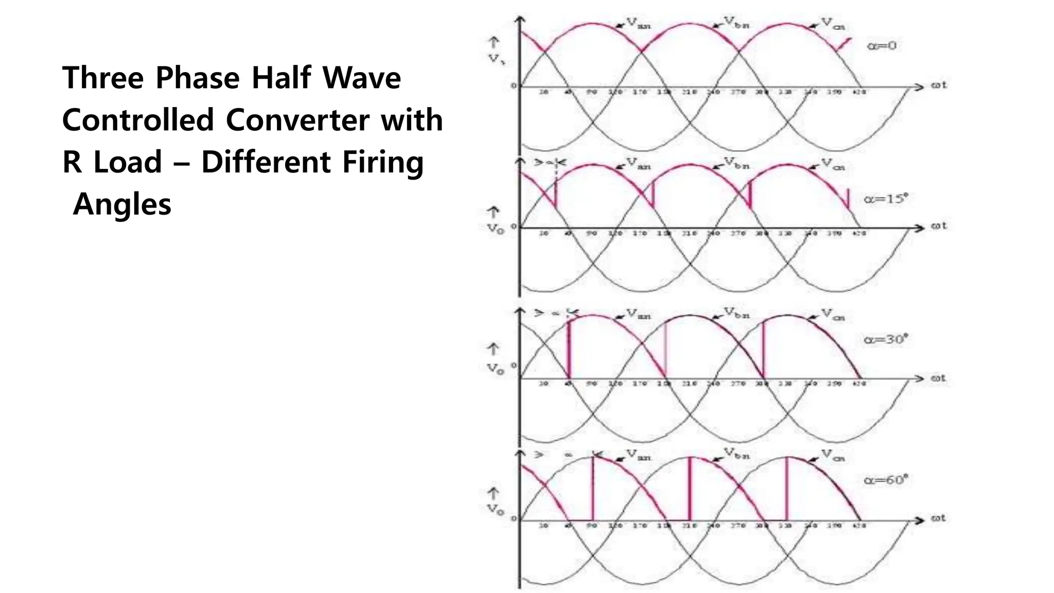
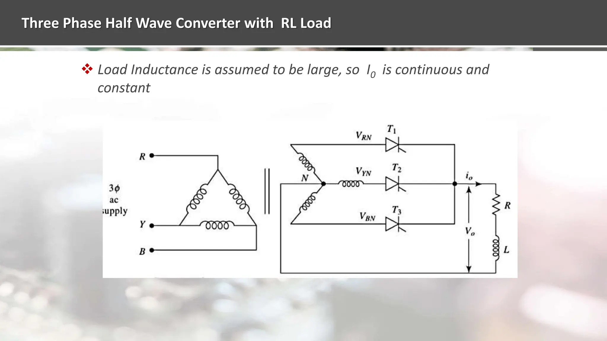
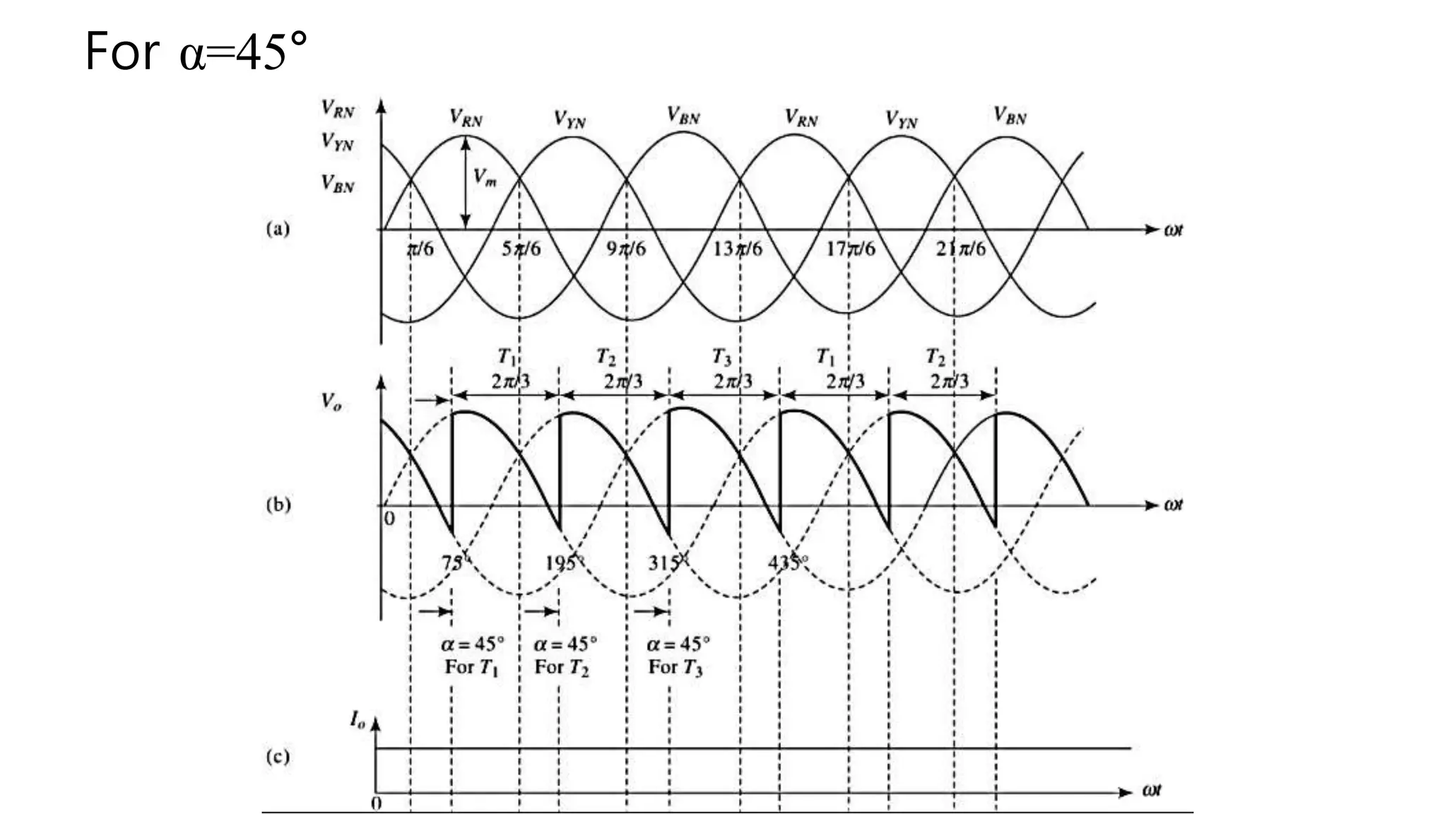
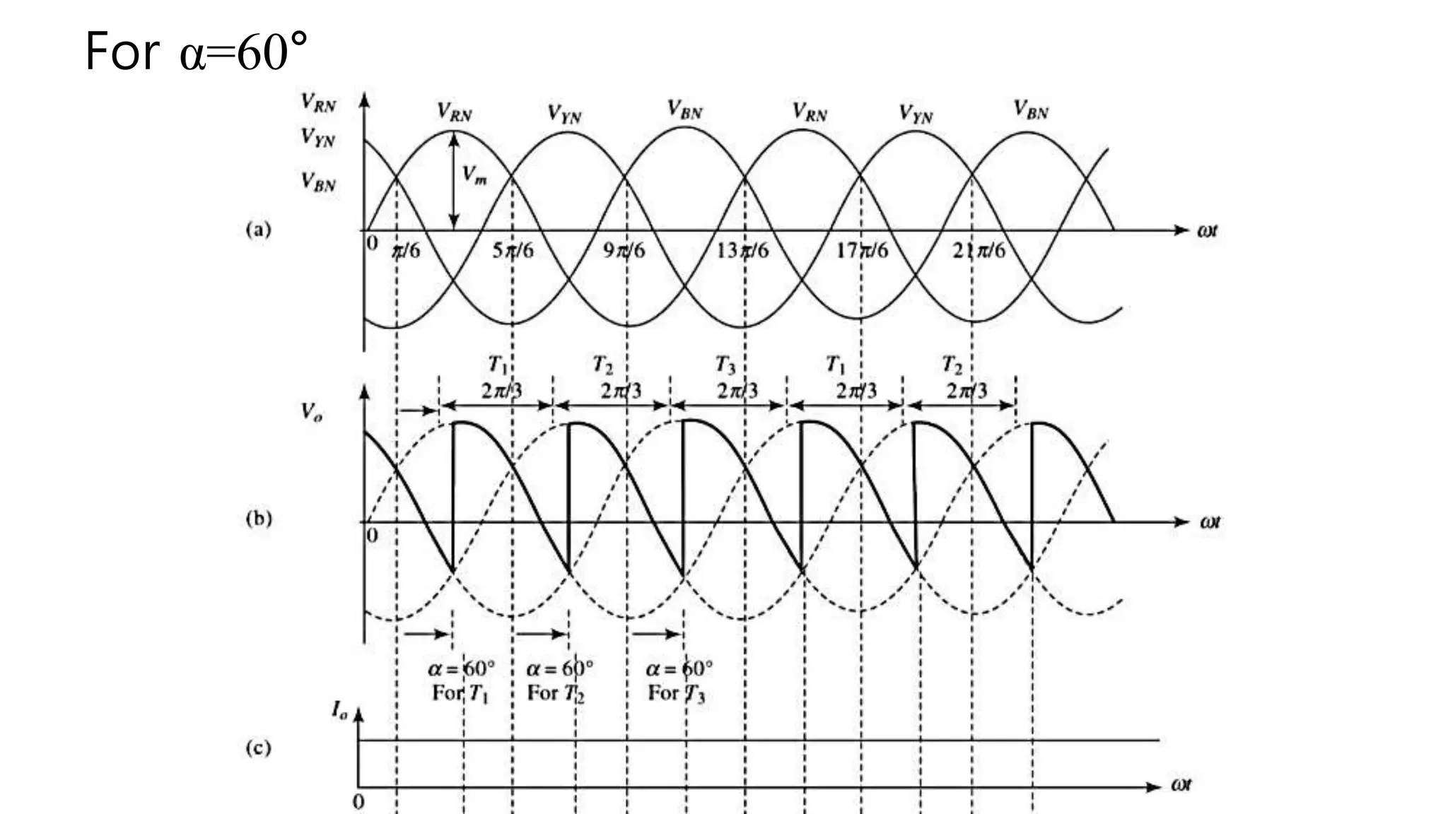
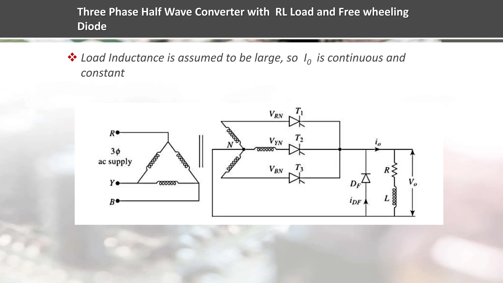
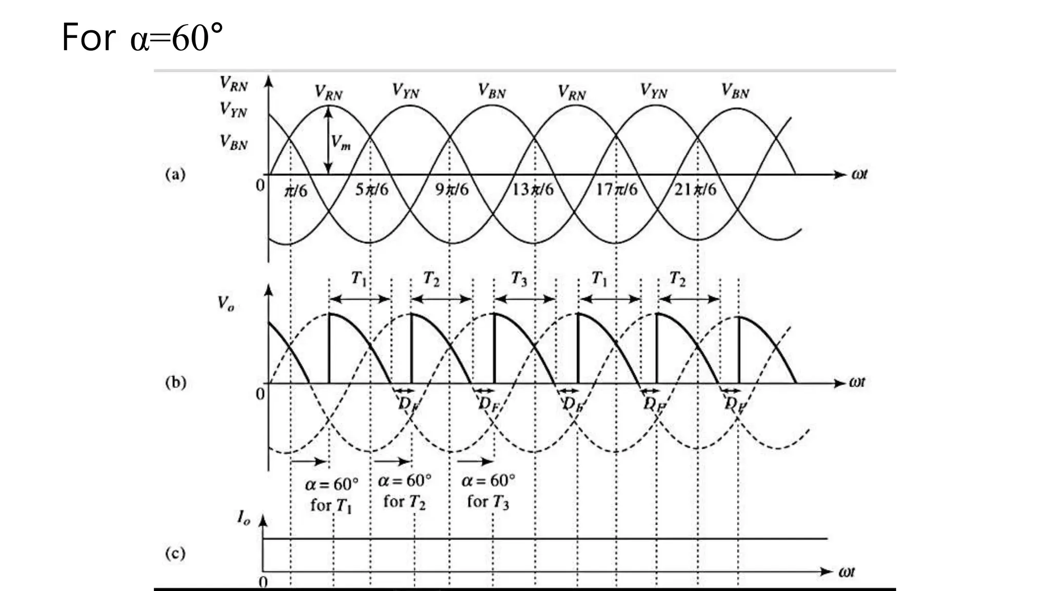
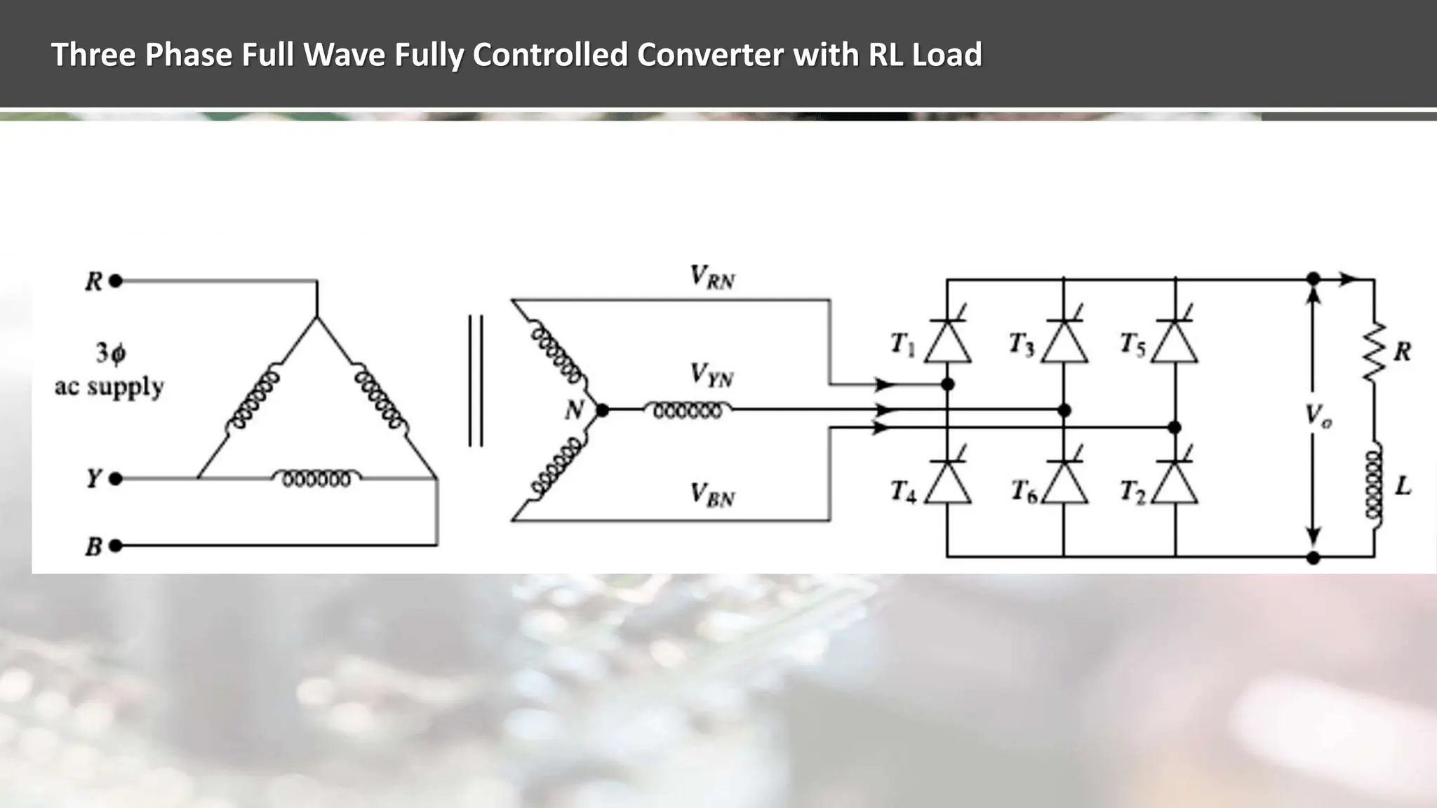
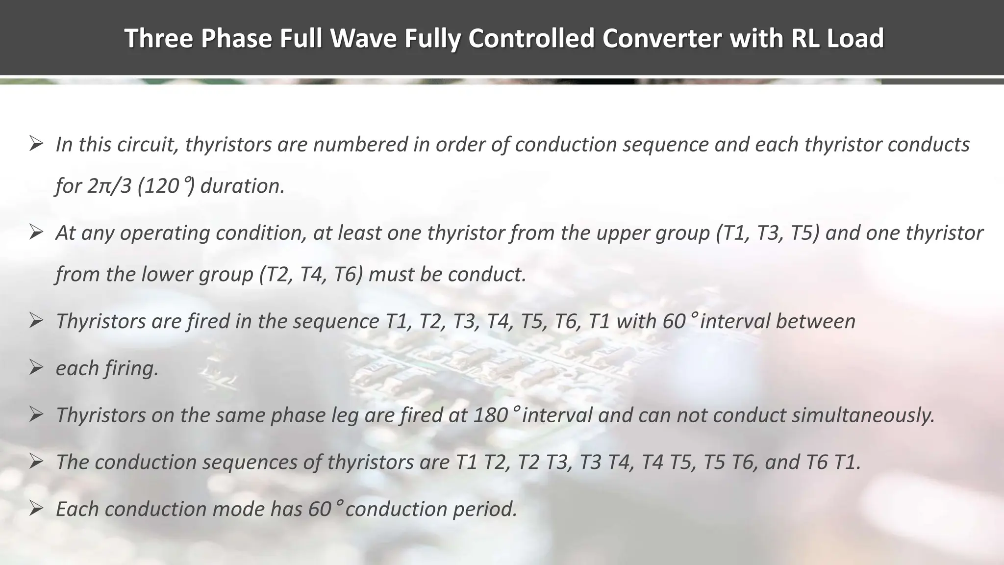
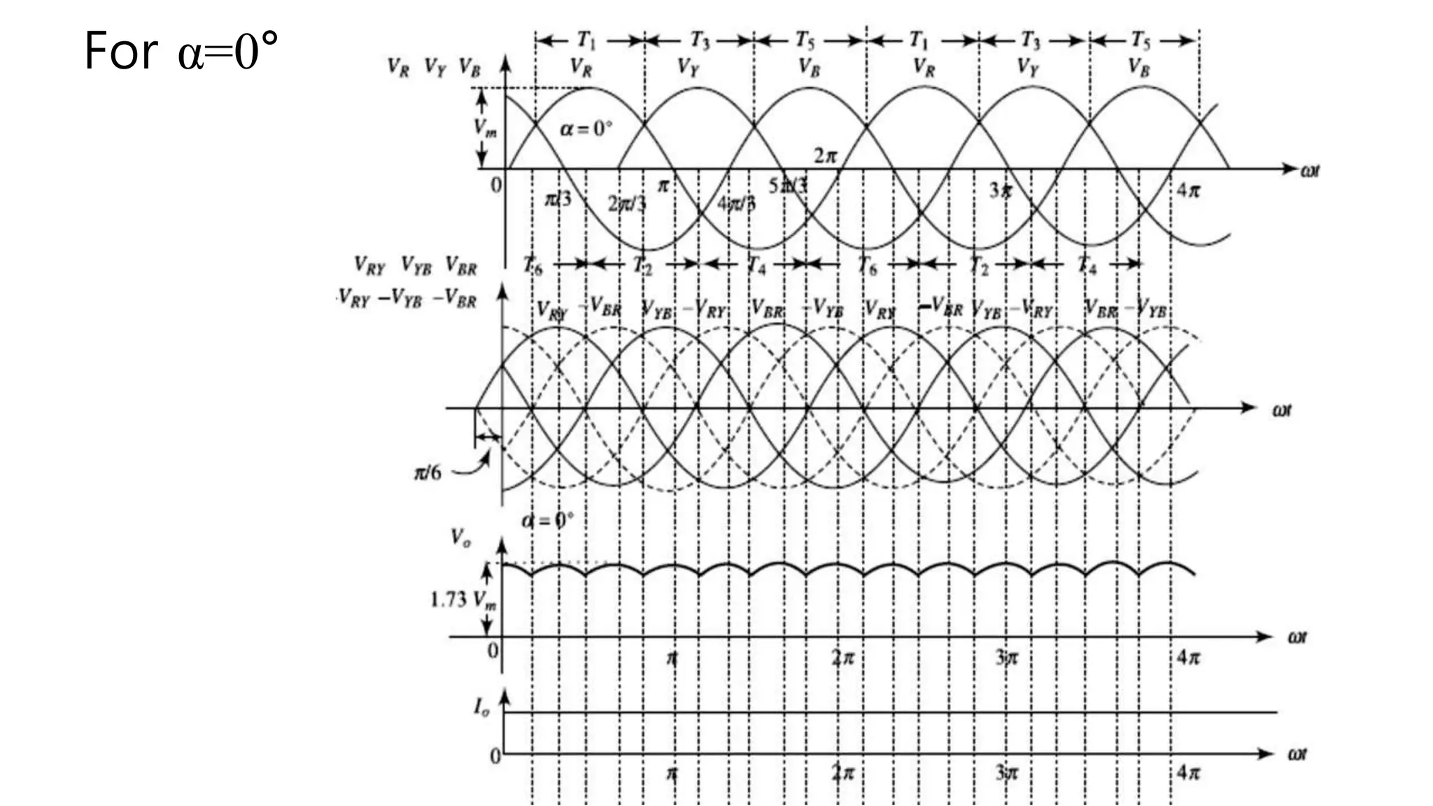
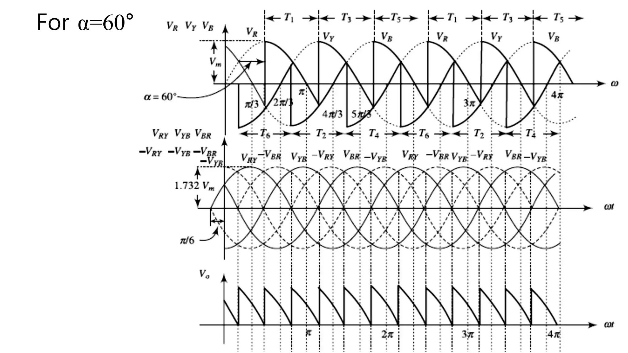
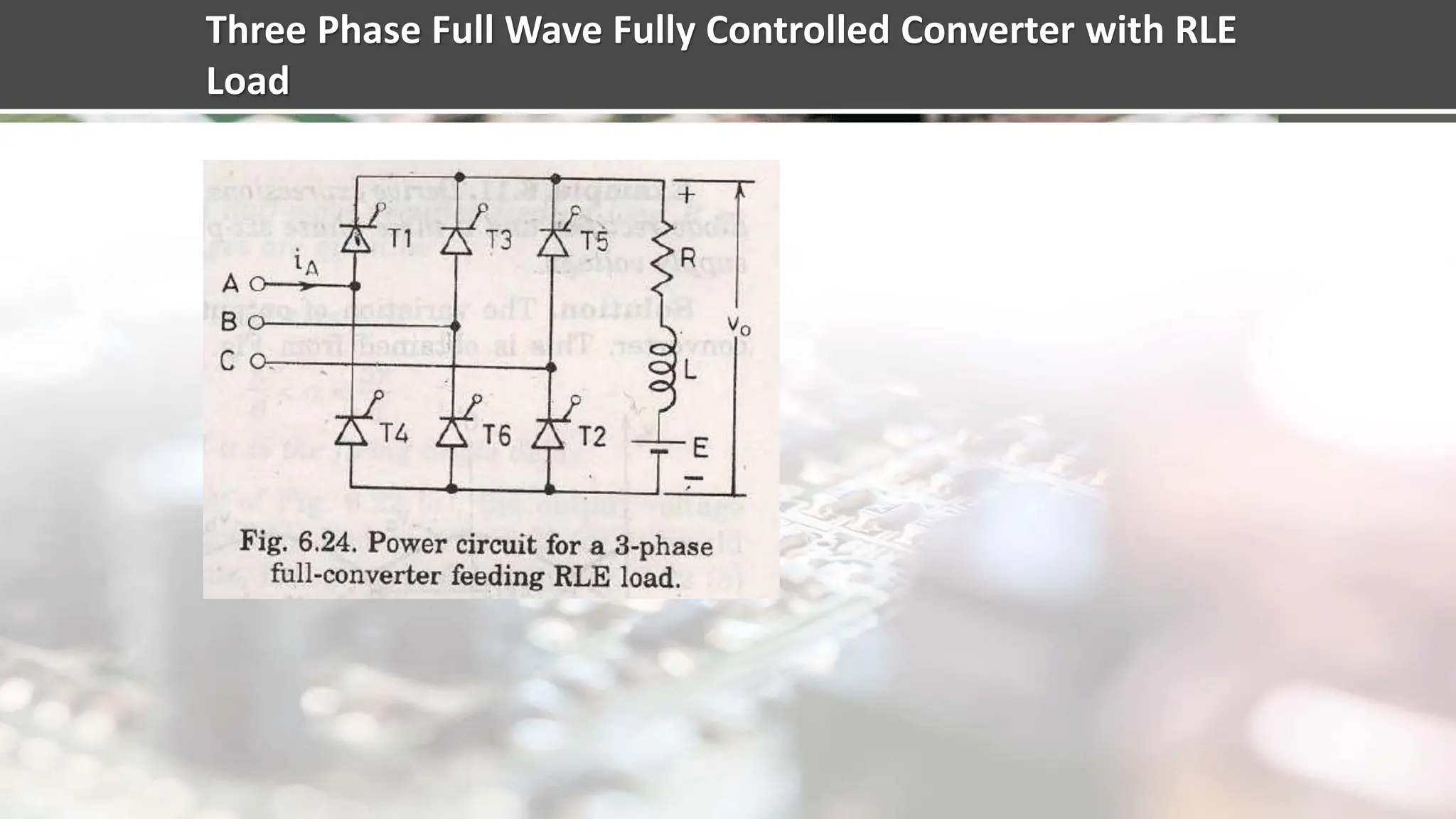
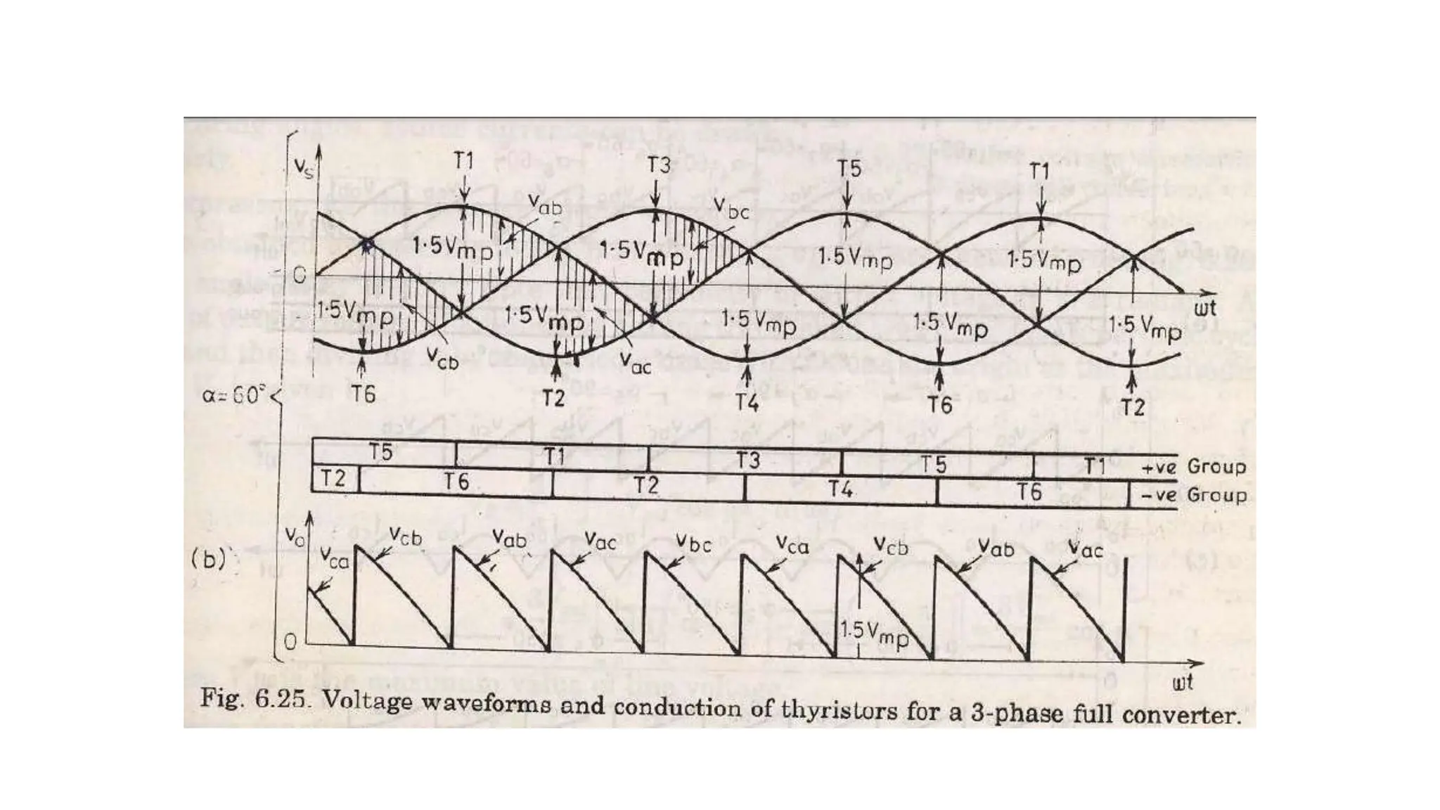
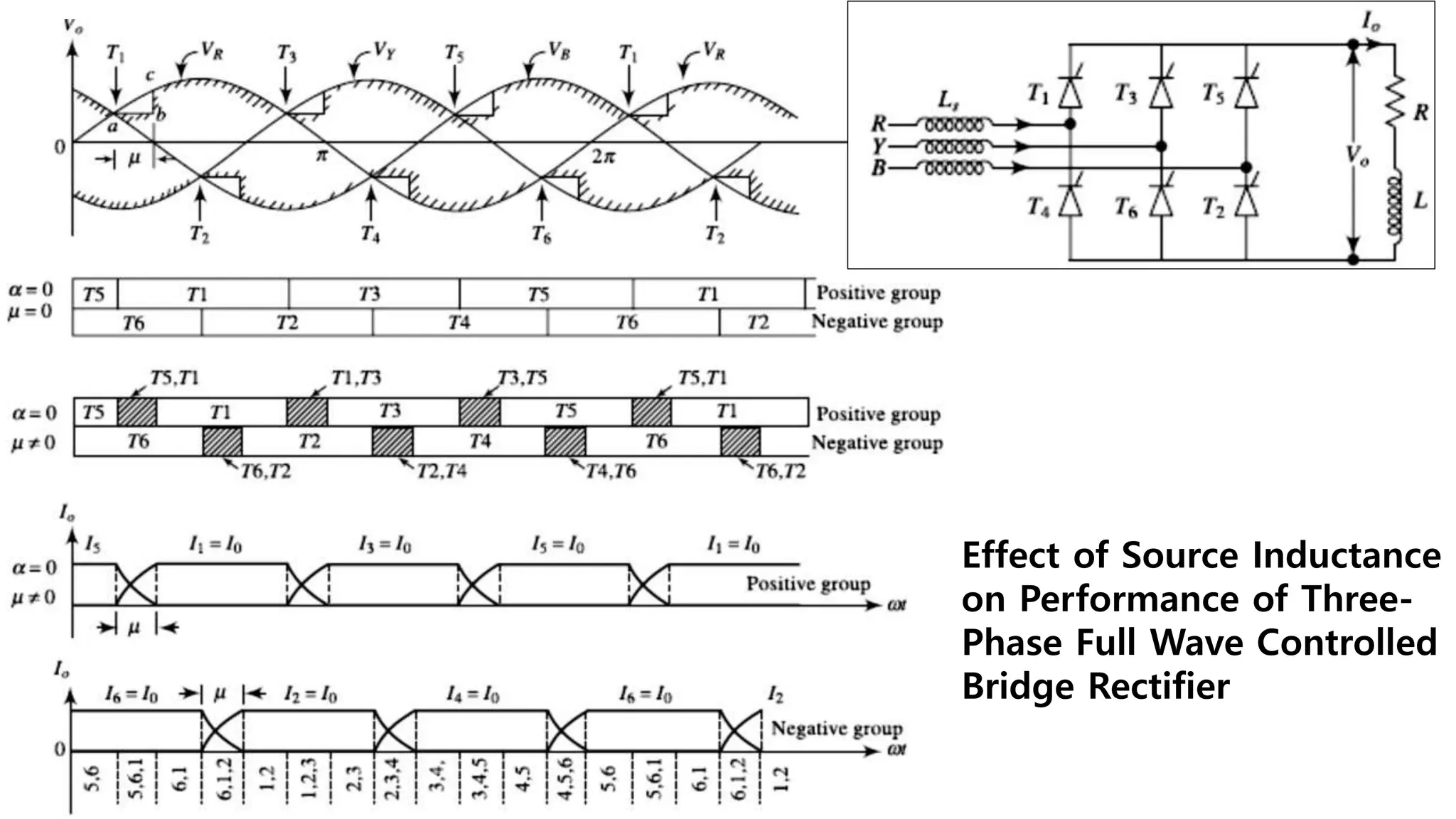
Introduction to three-phase thyristor converters, their advantages, types, and operational modes.
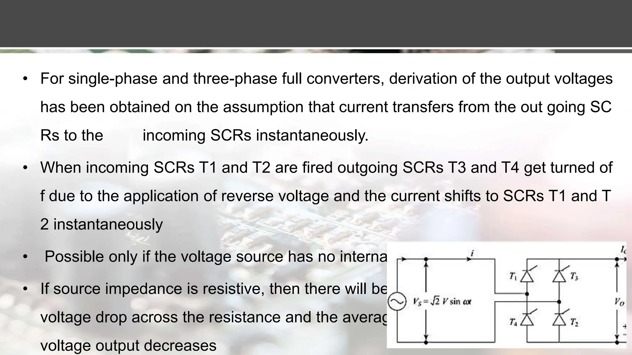
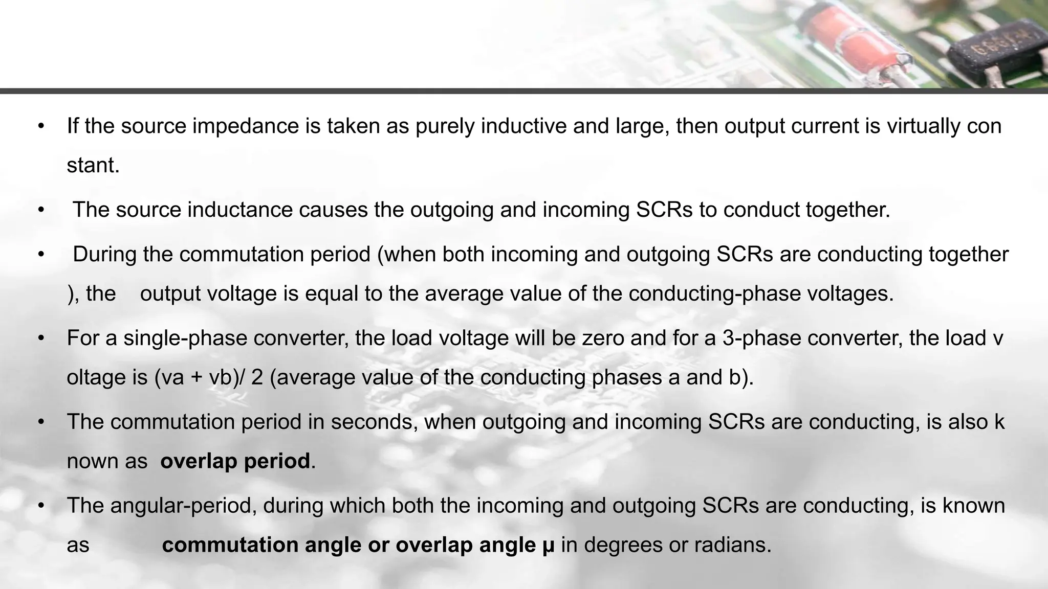
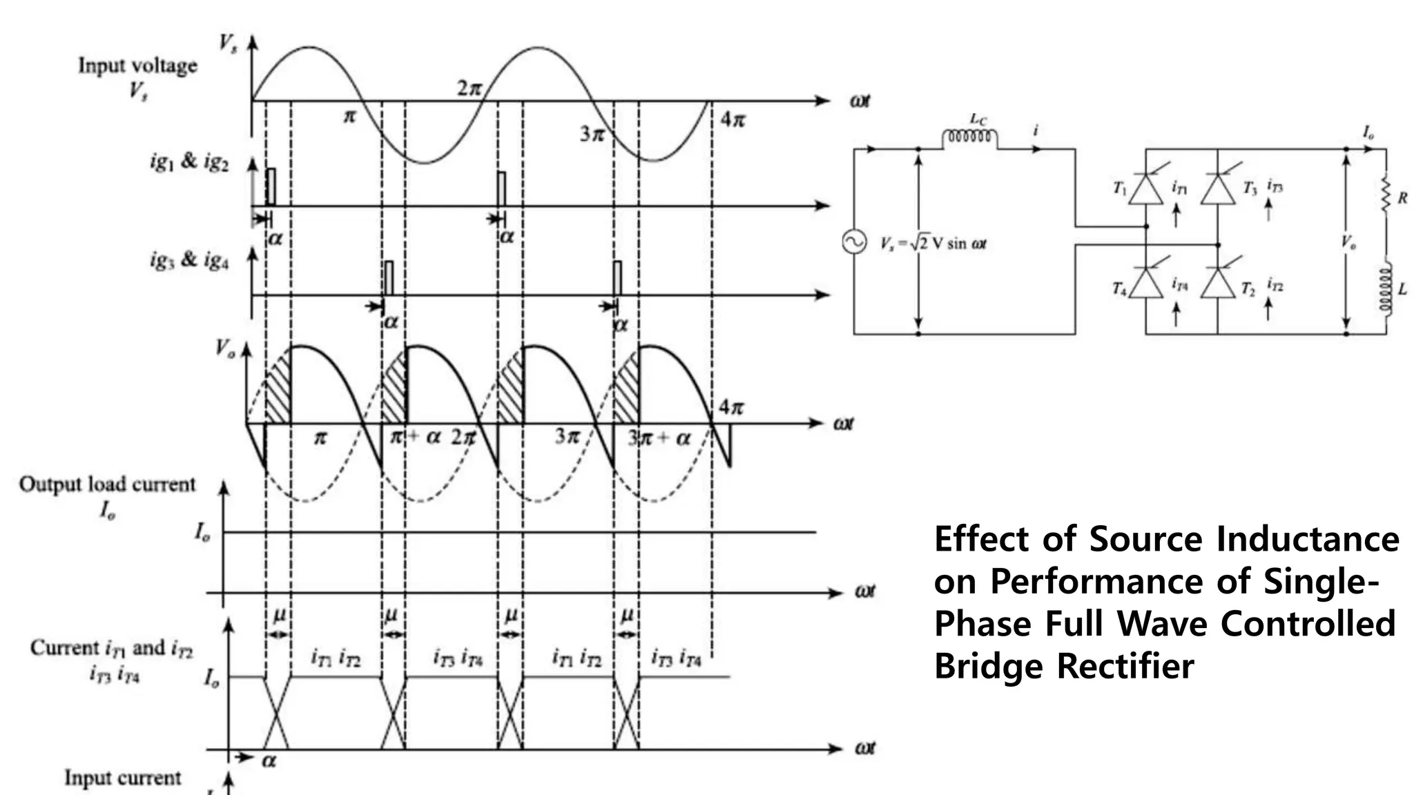
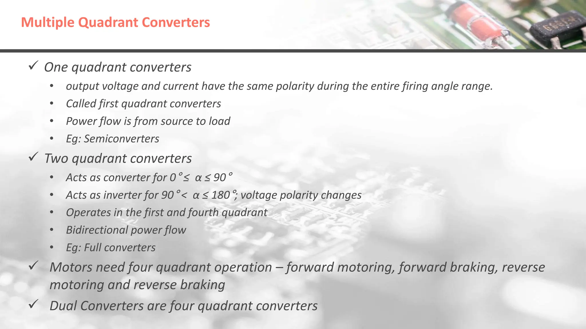
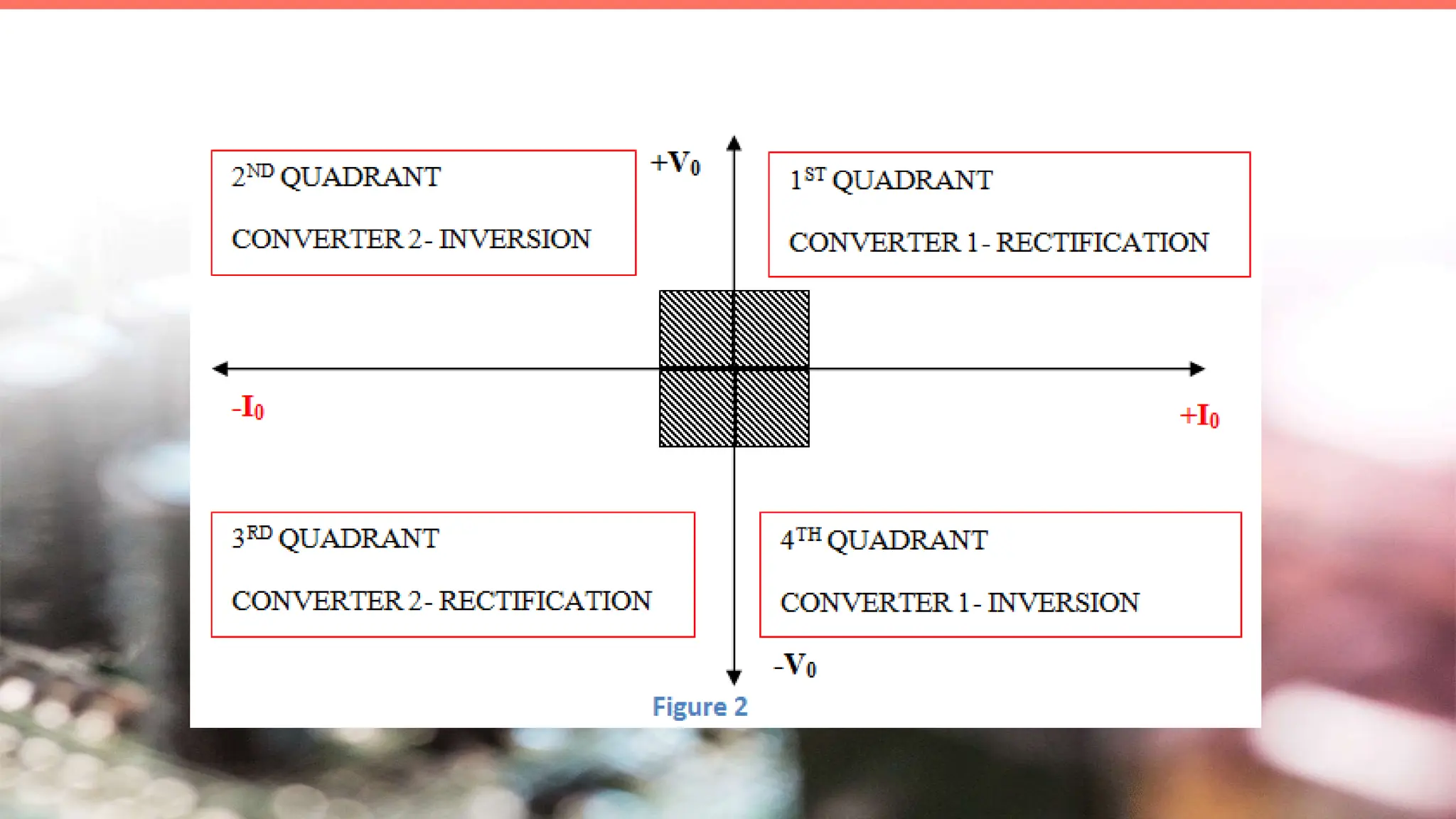
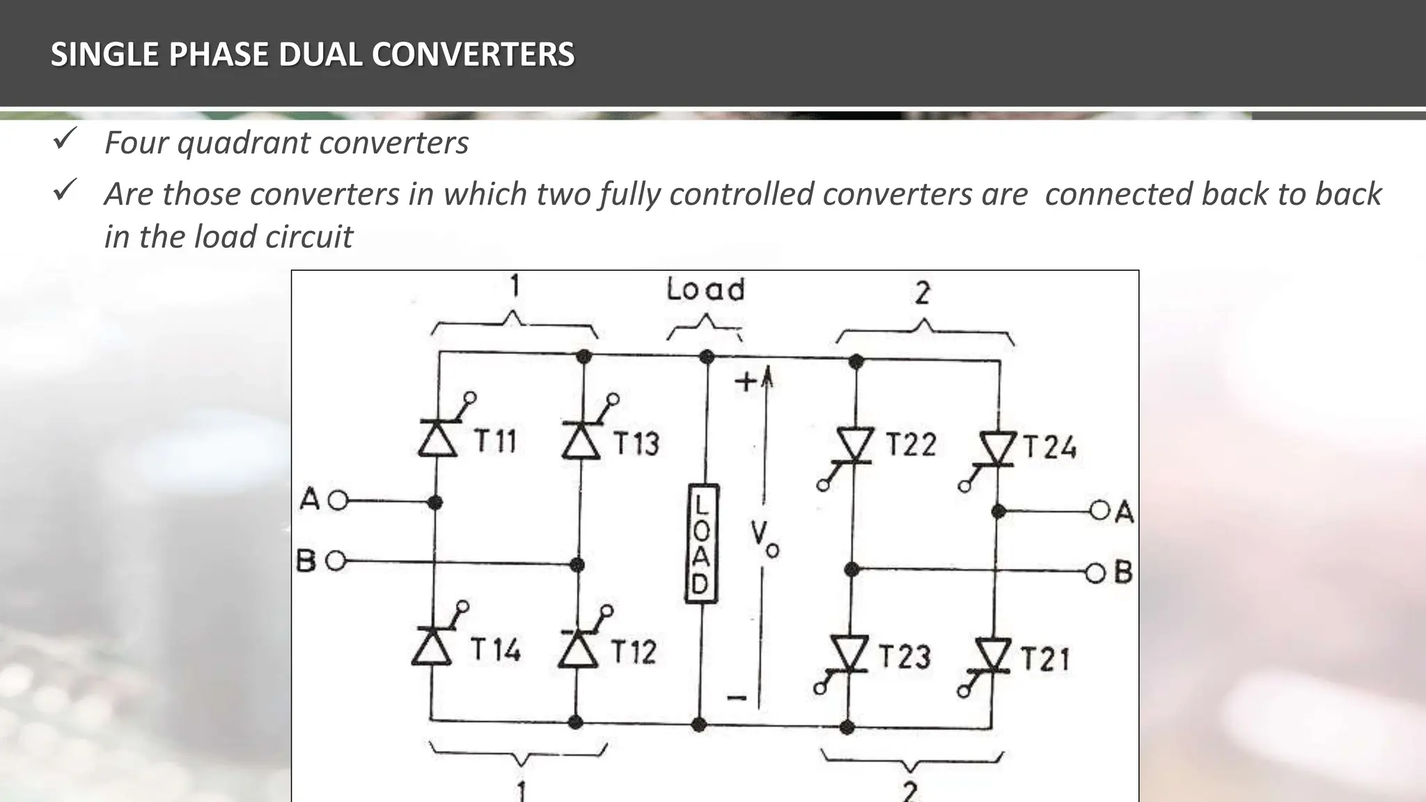
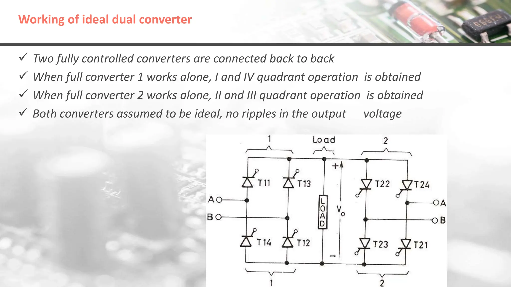
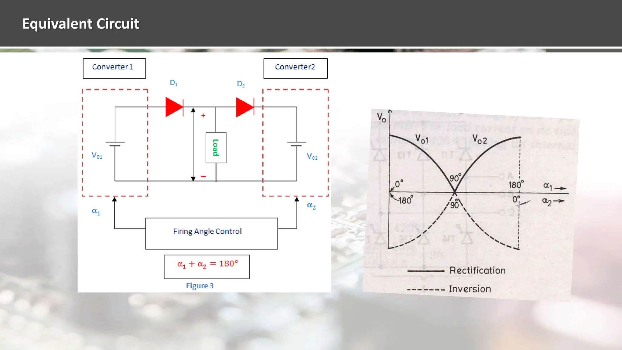
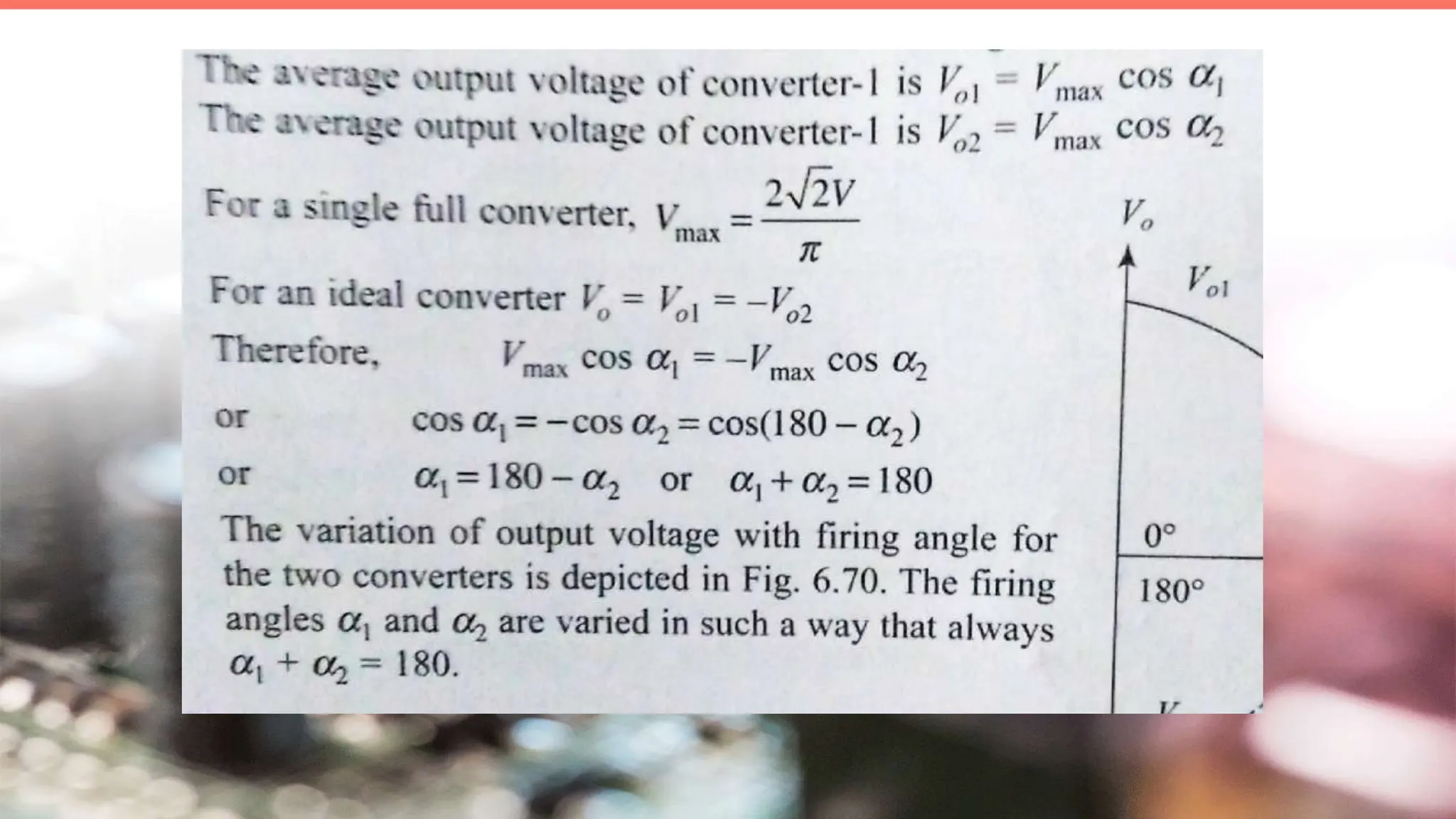
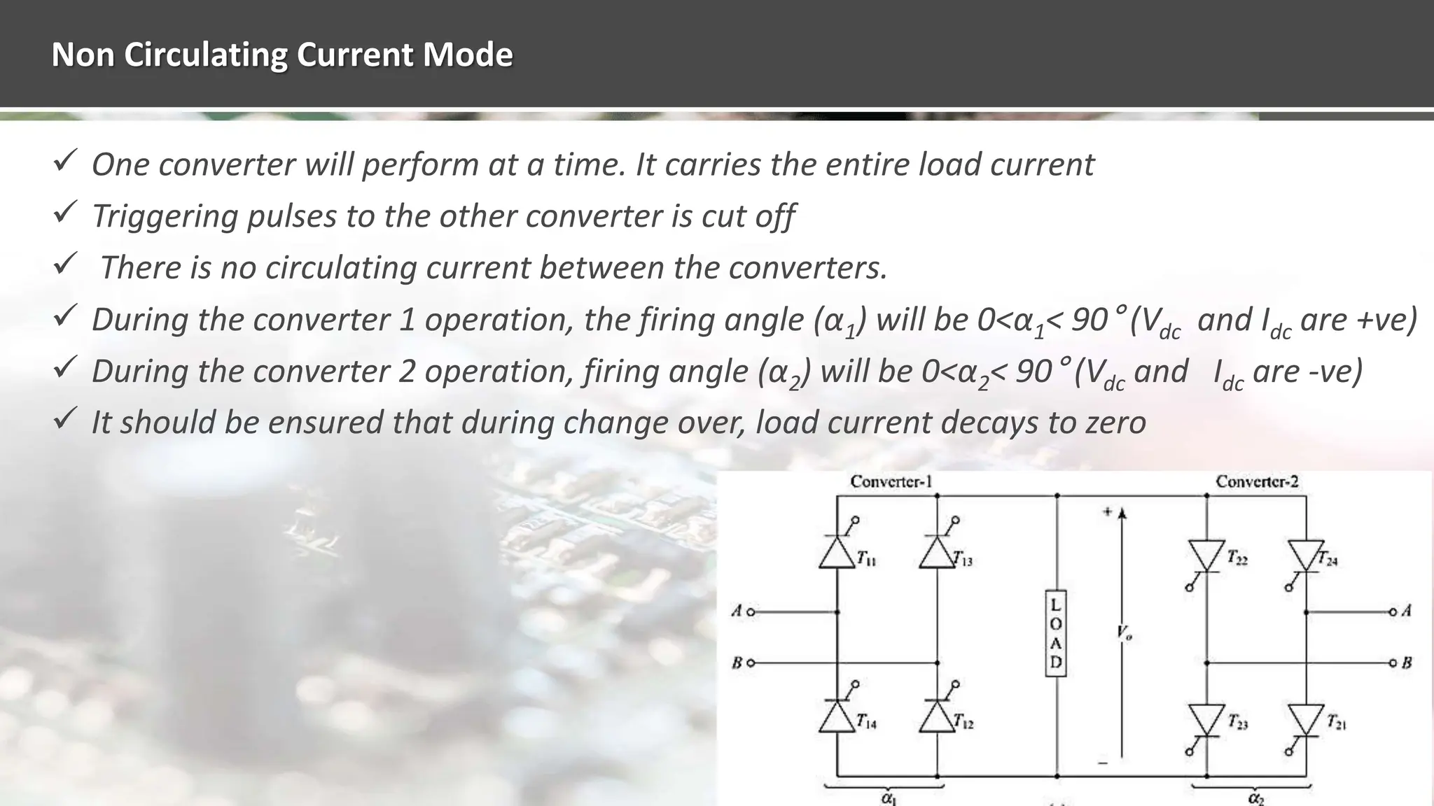
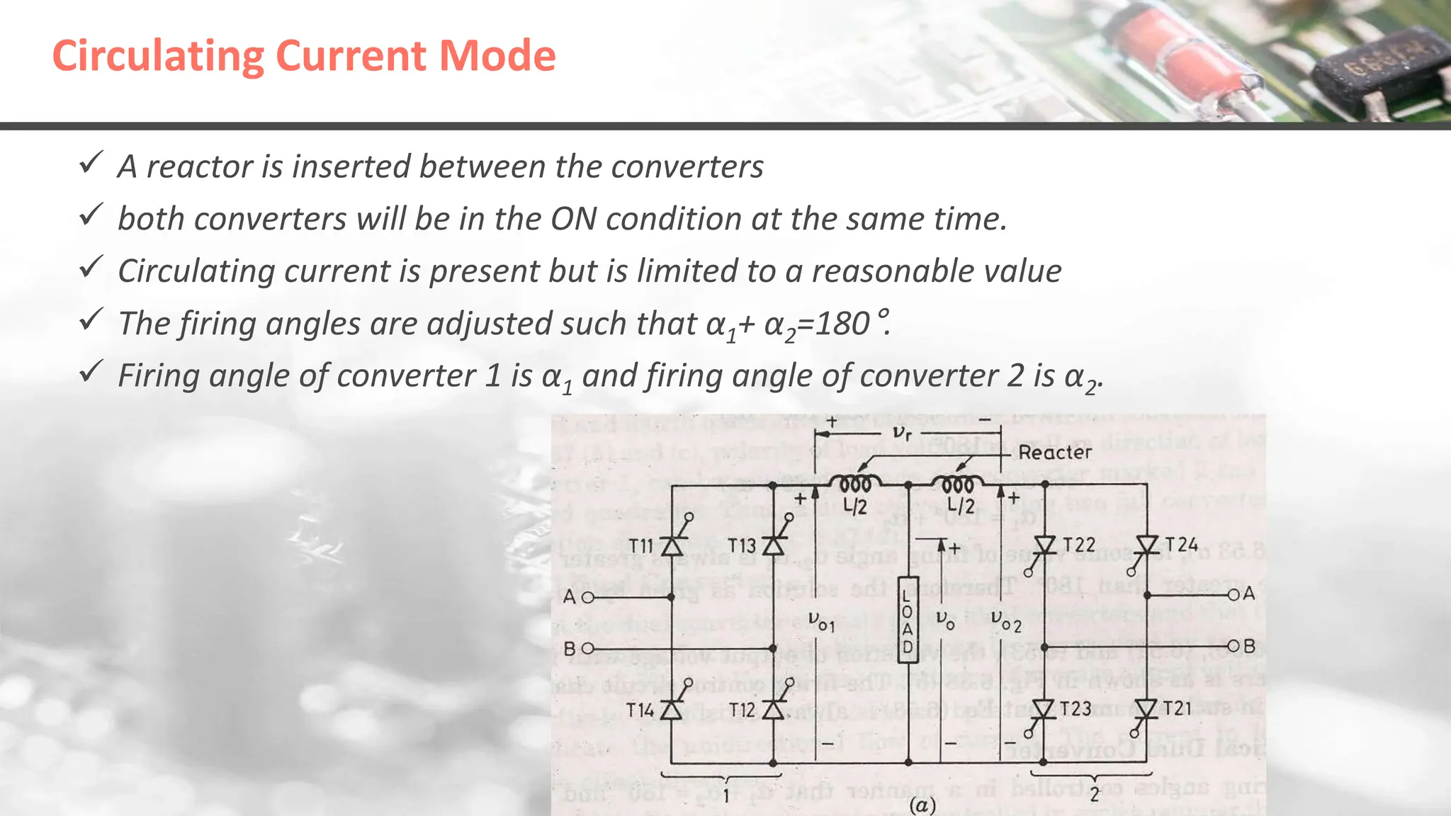
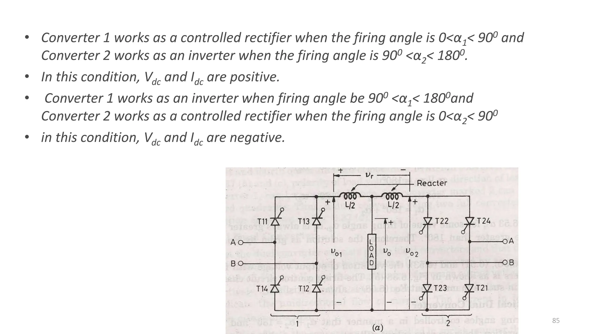
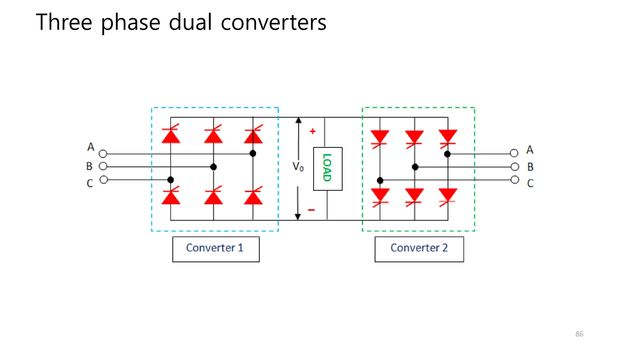
Evaluates the impact of source inductance on converters, and describes the functioning and applications of dual converters.