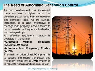
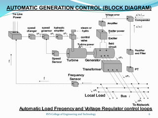
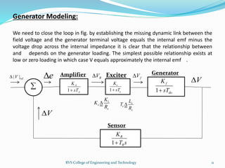
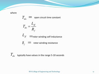
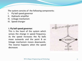
1RVS College of Engineering and Technology
•Automatic generation control An Introduction
•The need of Automatic Generation Control
•Reasons for limiting frequency deviations
•Automatic generation control (Block diagram)
•Automatic voltage regulator(AVR)
•Automatic load frequency control(ALFC)
•Exciter modelling
•Generator modeling
•Speed governing system
•Future work
2RVS College of Engineering and Technology
In an electric power system, automatic
generation control (AGC) is a system for
adjusting the power output of multiple
generators at different power plants, in
response to changes in the load. Since a
power grid requires that generation and load
closely balance moment by moment, frequent
adjustments to the output of generators are
necessary. The balance can be judged by
measuring the system frequency; if it is
increasing, more power is being generated
than used, which causes all the machines in
the system to accelerate. If the system
frequency is decreasing, more load is on the
system than the instantaneous generation can
provide, which causes all generators to slow
down.
3RVS College of Engineering and Technology
As our development has increased,
there has been a higher demand of
electrical power loads both on industrial
and domestic scale. As the number
increases, it is also imperative to
manage load properly since a failure to
do so results in frequency fluctuation
and voltage drops.
An effective regulatory strategy is
available in the form of
•Automatic Voltage Regulator
Systems (AVR) and
•Automatic Load Frequency Control
(ALFC)
The main function of ALFC system is
to assess and rectify the power and
frequency while that of AVR system is
to regulate voltage and reactive power.
The Need of Automatic Generation Control
4RVS College of Engineering and Technology
REASONS FOR LIMITING FREQUENCY DEVIATIONS
There are few reasons as to why there should be strict limitations on
frequency deviations and keeping the system frequency constant. They
are as follows:
•The three phase a.c. motors running speed are directly proportional to
the frequency. So the variation of system frequency will directly affect the
motor performance.
•The blades of the steam turbine and the water turbines are designed to
operate at a particular speed and the frequency variations will cause
change in the speed. This will lead to excessive vibration and cause
damage to the turbine blades.
•The frequency error may produce havoc in the digital storage and
retrieval process.
5RVS College of Engineering and Technology
AUTOMATIC GENERATION CONTROL (BLOCK DIAGRAM)
6RVS College of Engineering and Technology
The exciter is the main
component in the AVR loop. It
delivers the DC power to the
generator field. It must have
adequate power capacity and
sufficient speed of response.
The basic role of the AVR is to
provide constancy of the
generator terminal voltage
during normal and slow
changes in the load.
Automatic Voltage Regulator(AVR)
7RVS College of Engineering and Technology
| | | |refV V e   
Exciter Modelling:
Mathematical modelling of the exciter and its controls follows:
and
R Av K e  
where is amplifier gainAK
Laplace Transformation of these two equations yields
| | ( ) | | ( ) ( )refV s V s e s   
and ( )
( )
R
A A
v s
G K
e s

 

where is amplifier transfer functionAG
In reality the amplifier will have a delay that can be represented by a time constant AT
and its transfer function will then be of the form
( )
( ) 1
R A
A
A
v s K
G
e s sT

 
 
8RVS College of Engineering and Technology
If and represent respectively the resistance and inductance of the exciter field
we have for voltage equilibrium in the latter
eR eL
( )e
R e e e
d i
v R i L
dt

   
Measured across the main field the exciter produces armature volts per ampere of
field current , that is, we have the proportionality
1K
ei
1f ev K i  
Upon Laplace Transformation of the last two equations and elimination of we
obtain the transfer function of the exciter
ei
( )
( ) 1
f e
e
R e
v s K
G
v s sT

 
 
where 1
e
e
K
K
R

e
e
e
L
T
R
and
The time constants and have values in the ranges 0.02-0.10 and 0.5-1.0 seconds
respectively.
AT eT
9RVS College of Engineering and Technology
| |refV e
1
A
A
K
sT
RV
1
e
e
K
sT
fV
1
e
e
K
K
R

e
e
e
L
T
R


Linear model of the comparator-amplifier-exciter portion of AVR loop
V
10RVS College of Engineering and Technology
Amplifier Exciter
Comparator
Generator Modeling:
We need to close the loop in fig. by establishing the missing dynamic link between the
field voltage and the generator terminal voltage equals the internal emf minus the
voltage drop across the internal impedance it is clear that the relationship between
and depends on the generator loading. The simplest possible relationship exists at
low or zero loading in which case V equals approximately the internal emf .
| |refV e
1
A
A
K
sT
RV
1
e
e
K
sT
fV
1
e
e
K
K
R
 e
e
e
L
T
R

 1
f
do
K
sT
V
V
11RVS College of Engineering and Technology
1
R
R
K
T s
Amplifier Exciter Generator
Sensor
ff
do
f
L
T
R

where
doT  open circuit time constant
ffL rotor winding self inductance
fR  rotor winding resistance
doT typically have values in the range 5-10 seconds
12RVS College of Engineering and Technology
RVS College of Engineering and Technology 13
MATLAB Simlation of AVR
Amplifier KA=10 TA=0.1
Exciter Ke=1 Te=0.4
Generator Kf=1 Tdo=0.2
Sensor Kr=2 Tr=0.05
RVS College of Engineering and Technology 14
AUTOMATIC LOAD FREQUENCY CONTROL(ALFC)
The basic role of ALFC is :
•To maintain desired megawatt output of a generator unit matching
with the changing load
•To assist in controlling the frequency of larger interconnection
•To keep the net interchange power between pool members at the
predetermined value
The ALFC loop will maintain control only during normal (small and
slow) changes in load and frequency. It is typically unable to provide
adequate control during emergency situations, when large megawatt
imbalance occur. Then more drastic emergency control must be
applied.
15RVS College of Engineering and Technology
SPEED GOVERNI`NG SYSTEM
16RVS College of Engineering and Technology
The system consists of the following components:
I. Fly ball speed governor
II. Hydraulic amplifier
III. Linkage mechanism
IV. Speed changer
I. Fly ball speed governor:
This is the heart of the system which
senses the change in speed frequency.
As the speed increases the fly balls
move outwards and the point B on
linkage mechanism moves downwards.
The reverse happens when the speed
decreases
17RVS College of Engineering and Technology
II.Hydraulic amplifier:
It comprises a pilot valve and main piston arrangement. Low power level pilot
valve movement is converted into high power level piston valve movement. This
is necessary in order to open or close the steam valve against high pressure
steam.
III.Linkage mechanism:
ABC is a rigid link pivoted at B and CDE is another rigid link pivoted at D.
This link mechanism provides a movement to the control valve in proportion
to change in speed. It also provides a feedback from the steam valve
movement
18RVS College of Engineering and Technology
IV. Speed changer:
It provides a steady state power output setting
for the turbine. Its downward movement opens
the upper pilot valve so that more steam is
admitted to the turbine under steady
conditions. The e reverse happens for upward
movement of speed changer
19RVS College of Engineering and Technology
RVS College of Engineering and Technology 20
1
sg
sg
K
T s 1
t
t
K
T s 1
ps
ps
K
T s
1
R
 
Speed Governer Turbine Generator Load
Sensor
Modeling of Automatic Load Frequency Control
( )cP s
( )EY s ( ) ( )t gP s P s  
( )DP s
( )F s
RVS College of Engineering and Technology 21
MATLAB Simlation of ALFC
Speed Governor Ksg=1 Tsg=0.2
Turbine Kt=1 Tt=0.5
Generator Load Kps=1 Tps=10
Sensor R=0.05
RVS College of Engineering and Technology 22
23RVS College of Engineering and Technology

Automatic Generation Control

  • 1.
    1RVS College ofEngineering and Technology
  • 2.
    •Automatic generation controlAn Introduction •The need of Automatic Generation Control •Reasons for limiting frequency deviations •Automatic generation control (Block diagram) •Automatic voltage regulator(AVR) •Automatic load frequency control(ALFC) •Exciter modelling •Generator modeling •Speed governing system •Future work 2RVS College of Engineering and Technology
  • 3.
    In an electricpower system, automatic generation control (AGC) is a system for adjusting the power output of multiple generators at different power plants, in response to changes in the load. Since a power grid requires that generation and load closely balance moment by moment, frequent adjustments to the output of generators are necessary. The balance can be judged by measuring the system frequency; if it is increasing, more power is being generated than used, which causes all the machines in the system to accelerate. If the system frequency is decreasing, more load is on the system than the instantaneous generation can provide, which causes all generators to slow down. 3RVS College of Engineering and Technology
  • 4.
    As our developmenthas increased, there has been a higher demand of electrical power loads both on industrial and domestic scale. As the number increases, it is also imperative to manage load properly since a failure to do so results in frequency fluctuation and voltage drops. An effective regulatory strategy is available in the form of •Automatic Voltage Regulator Systems (AVR) and •Automatic Load Frequency Control (ALFC) The main function of ALFC system is to assess and rectify the power and frequency while that of AVR system is to regulate voltage and reactive power. The Need of Automatic Generation Control 4RVS College of Engineering and Technology
  • 5.
    REASONS FOR LIMITINGFREQUENCY DEVIATIONS There are few reasons as to why there should be strict limitations on frequency deviations and keeping the system frequency constant. They are as follows: •The three phase a.c. motors running speed are directly proportional to the frequency. So the variation of system frequency will directly affect the motor performance. •The blades of the steam turbine and the water turbines are designed to operate at a particular speed and the frequency variations will cause change in the speed. This will lead to excessive vibration and cause damage to the turbine blades. •The frequency error may produce havoc in the digital storage and retrieval process. 5RVS College of Engineering and Technology
  • 6.
    AUTOMATIC GENERATION CONTROL(BLOCK DIAGRAM) 6RVS College of Engineering and Technology
  • 7.
    The exciter isthe main component in the AVR loop. It delivers the DC power to the generator field. It must have adequate power capacity and sufficient speed of response. The basic role of the AVR is to provide constancy of the generator terminal voltage during normal and slow changes in the load. Automatic Voltage Regulator(AVR) 7RVS College of Engineering and Technology
  • 8.
    | | ||refV V e    Exciter Modelling: Mathematical modelling of the exciter and its controls follows: and R Av K e   where is amplifier gainAK Laplace Transformation of these two equations yields | | ( ) | | ( ) ( )refV s V s e s    and ( ) ( ) R A A v s G K e s     where is amplifier transfer functionAG In reality the amplifier will have a delay that can be represented by a time constant AT and its transfer function will then be of the form ( ) ( ) 1 R A A A v s K G e s sT      8RVS College of Engineering and Technology
  • 9.
    If and representrespectively the resistance and inductance of the exciter field we have for voltage equilibrium in the latter eR eL ( )e R e e e d i v R i L dt      Measured across the main field the exciter produces armature volts per ampere of field current , that is, we have the proportionality 1K ei 1f ev K i   Upon Laplace Transformation of the last two equations and elimination of we obtain the transfer function of the exciter ei ( ) ( ) 1 f e e R e v s K G v s sT      where 1 e e K K R  e e e L T R and The time constants and have values in the ranges 0.02-0.10 and 0.5-1.0 seconds respectively. AT eT 9RVS College of Engineering and Technology
  • 10.
    | |refV e 1 A A K sT RV 1 e e K sT fV 1 e e K K R  e e e L T R   Linearmodel of the comparator-amplifier-exciter portion of AVR loop V 10RVS College of Engineering and Technology Amplifier Exciter Comparator
  • 11.
    Generator Modeling: We needto close the loop in fig. by establishing the missing dynamic link between the field voltage and the generator terminal voltage equals the internal emf minus the voltage drop across the internal impedance it is clear that the relationship between and depends on the generator loading. The simplest possible relationship exists at low or zero loading in which case V equals approximately the internal emf . | |refV e 1 A A K sT RV 1 e e K sT fV 1 e e K K R  e e e L T R   1 f do K sT V V 11RVS College of Engineering and Technology 1 R R K T s Amplifier Exciter Generator Sensor
  • 12.
    ff do f L T R  where doT  opencircuit time constant ffL rotor winding self inductance fR  rotor winding resistance doT typically have values in the range 5-10 seconds 12RVS College of Engineering and Technology
  • 13.
    RVS College ofEngineering and Technology 13 MATLAB Simlation of AVR Amplifier KA=10 TA=0.1 Exciter Ke=1 Te=0.4 Generator Kf=1 Tdo=0.2 Sensor Kr=2 Tr=0.05
  • 14.
    RVS College ofEngineering and Technology 14
  • 15.
    AUTOMATIC LOAD FREQUENCYCONTROL(ALFC) The basic role of ALFC is : •To maintain desired megawatt output of a generator unit matching with the changing load •To assist in controlling the frequency of larger interconnection •To keep the net interchange power between pool members at the predetermined value The ALFC loop will maintain control only during normal (small and slow) changes in load and frequency. It is typically unable to provide adequate control during emergency situations, when large megawatt imbalance occur. Then more drastic emergency control must be applied. 15RVS College of Engineering and Technology
  • 16.
    SPEED GOVERNI`NG SYSTEM 16RVSCollege of Engineering and Technology
  • 17.
    The system consistsof the following components: I. Fly ball speed governor II. Hydraulic amplifier III. Linkage mechanism IV. Speed changer I. Fly ball speed governor: This is the heart of the system which senses the change in speed frequency. As the speed increases the fly balls move outwards and the point B on linkage mechanism moves downwards. The reverse happens when the speed decreases 17RVS College of Engineering and Technology
  • 18.
    II.Hydraulic amplifier: It comprisesa pilot valve and main piston arrangement. Low power level pilot valve movement is converted into high power level piston valve movement. This is necessary in order to open or close the steam valve against high pressure steam. III.Linkage mechanism: ABC is a rigid link pivoted at B and CDE is another rigid link pivoted at D. This link mechanism provides a movement to the control valve in proportion to change in speed. It also provides a feedback from the steam valve movement 18RVS College of Engineering and Technology
  • 19.
    IV. Speed changer: Itprovides a steady state power output setting for the turbine. Its downward movement opens the upper pilot valve so that more steam is admitted to the turbine under steady conditions. The e reverse happens for upward movement of speed changer 19RVS College of Engineering and Technology
  • 20.
    RVS College ofEngineering and Technology 20 1 sg sg K T s 1 t t K T s 1 ps ps K T s 1 R   Speed Governer Turbine Generator Load Sensor Modeling of Automatic Load Frequency Control ( )cP s ( )EY s ( ) ( )t gP s P s   ( )DP s ( )F s
  • 21.
    RVS College ofEngineering and Technology 21 MATLAB Simlation of ALFC Speed Governor Ksg=1 Tsg=0.2 Turbine Kt=1 Tt=0.5 Generator Load Kps=1 Tps=10 Sensor R=0.05
  • 22.
    RVS College ofEngineering and Technology 22
  • 23.
    23RVS College ofEngineering and Technology