Downloaded 278 times


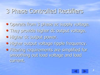


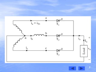
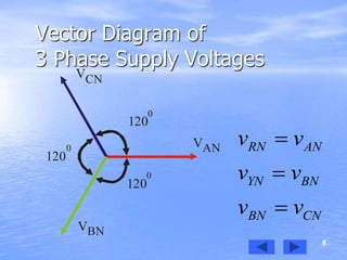

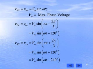
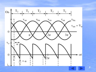
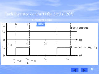

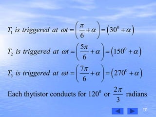
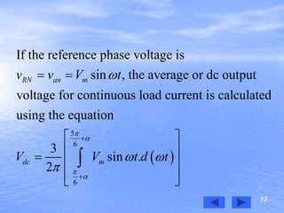
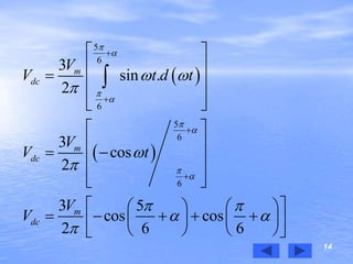
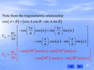
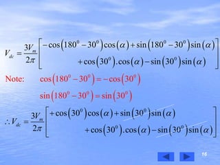
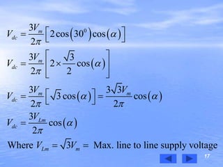
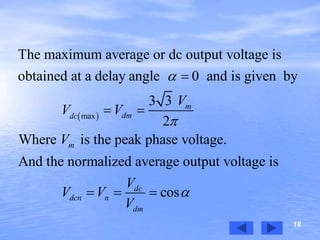
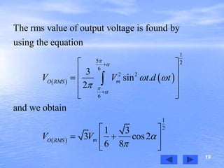

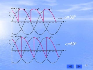
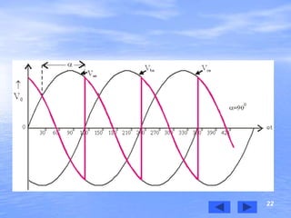

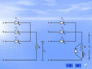


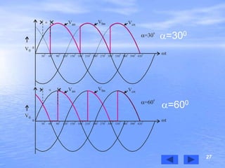

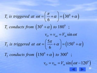
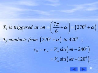
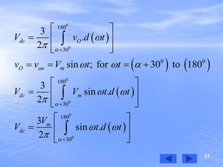
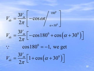


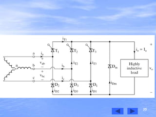

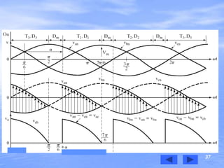
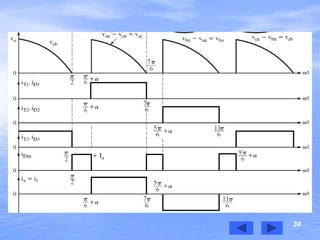
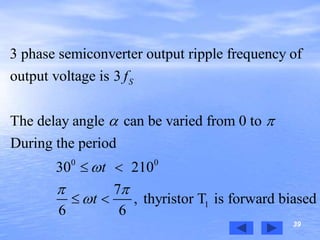


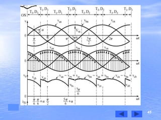
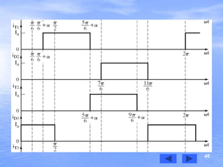
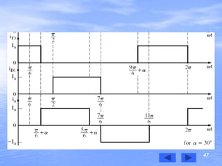

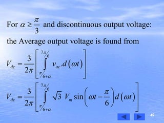
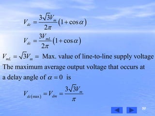
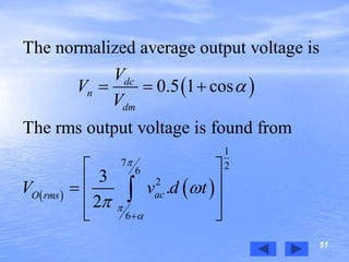
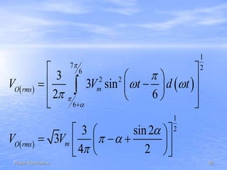
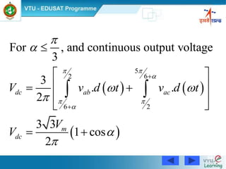
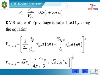
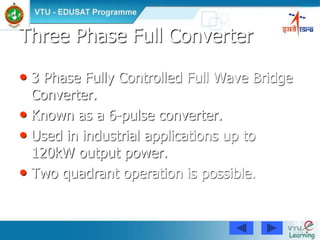
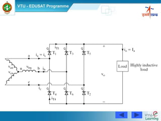
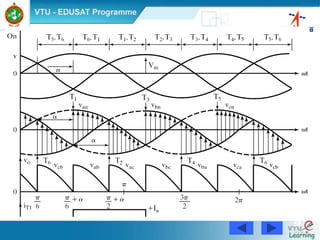

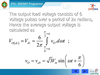
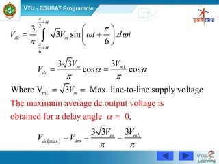
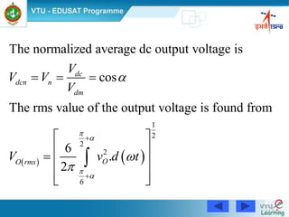
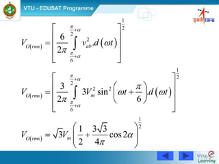
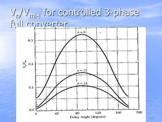
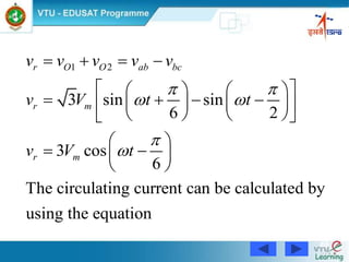
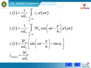
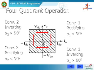


This document discusses three phase controlled rectifiers. It provides equations and diagrams for a three phase half-wave converter with an RL load operating under continuous and constant load current. The average output voltage is derived as one-third the peak phase voltage multiplied by 2/π. Waveforms at different trigger angles are shown. Methods for calculating the maximum, RMS, and normalized average output voltages are also presented.