Download as PDF, PPTX


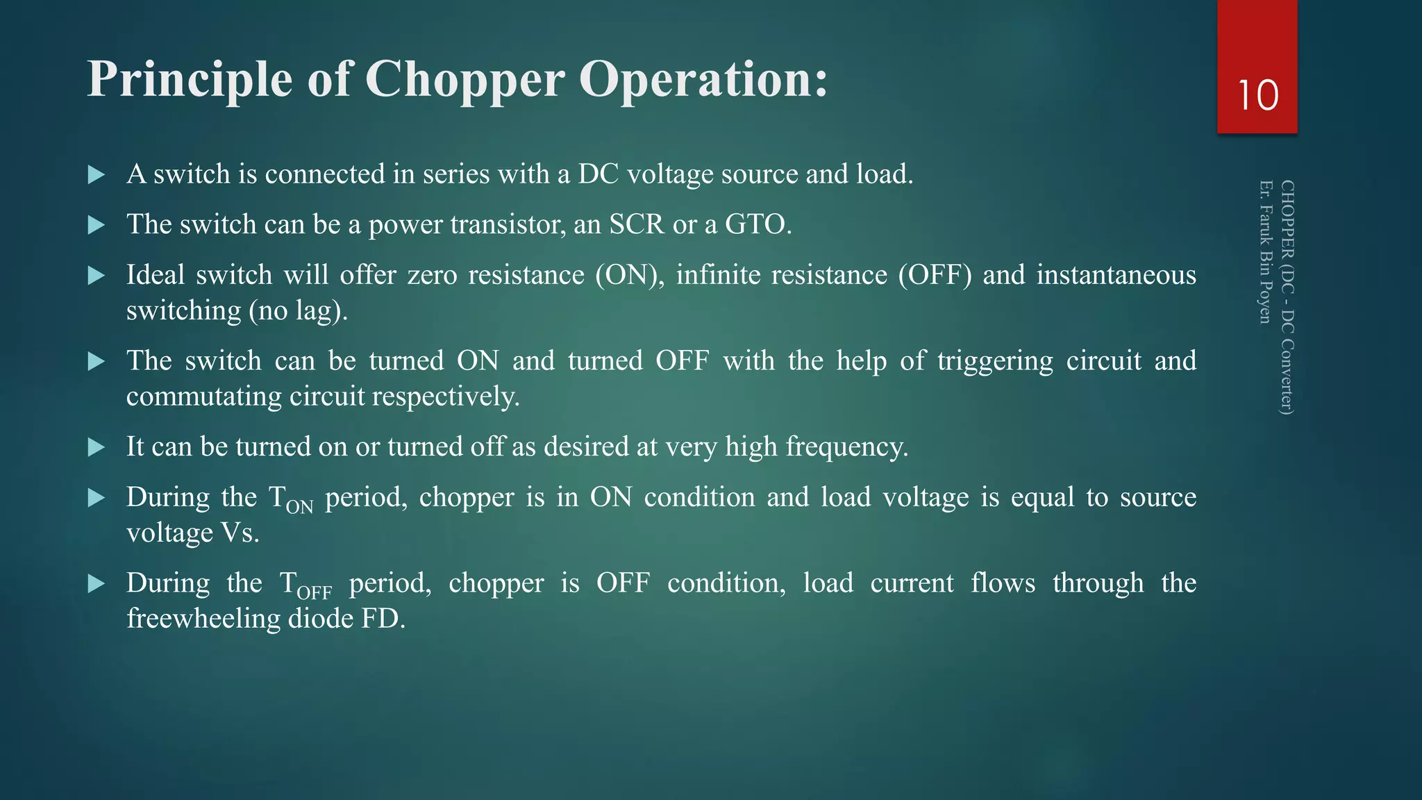

![Principle of Chopper Operation:
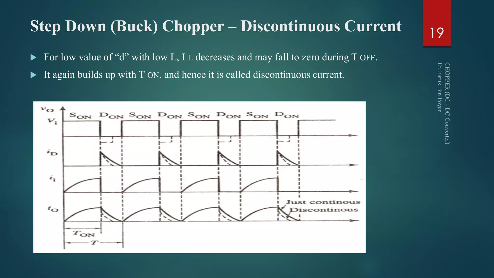
Hence it is concluded that the average load voltage can be controlled by varying the value
of TON and/of TOFF in the following two ways.
a) Varying TON and keeping the periodic time T constant. This is called constant frequency
system.
b) Variable frequency system. i.e. keeping either TON constant and varying TOFF or keeping
TOFF constant and varying TON.
VO = (TON/[TON+TOFF] )VS = (TON/T )VS = α. VS
Here α = Duty cycle = (TON/T); where T = TON +TOFF ;Chopper frequency f = 1/T
𝐸𝑓𝑓𝑒𝑐𝑡𝑖𝑣𝑒 𝑅𝑀𝑆 𝑂𝑢𝑝𝑢𝑡 𝑉𝑜𝑙𝑡𝑎𝑔𝑒 𝑉𝑂(𝑅𝑀𝑆) =
𝑉𝑖
2
𝑇𝑂𝑁
𝑇
= 𝑉𝑖
𝑇𝑂𝑁
𝑇
= 𝑉𝑖 𝑑
12](https://image.slidesharecdn.com/powerelectronics-6-171116173605/75/Power-Electronics-Chopper-dc-dc-converter-12-2048.jpg)


![C C Chopper – Design Consideration
Substituting the value of 𝐶 in 𝑉 𝑆
𝐶
𝐿
= 𝑥𝐼0, we get
𝑉 𝑆
𝐿
.
𝑇 𝐶
[𝜋−2𝑠𝑖𝑛−1 1
𝑥 ]
= 𝑥. 𝐼0
∴ 𝑳 =
𝑽 𝑺 𝑻 𝑪
𝒙. 𝑰 𝟎[𝝅 − 𝟐𝒔𝒊𝒏−𝟏 𝟏
𝒙 ]
𝐴𝑔𝑎𝑖𝑛 𝐿 =
1
𝑇 𝐶
[𝜋 − 2𝑠𝑖𝑛−1 1
𝑥 ] 𝐶
𝑪 =
𝒙. 𝑰 𝟎 𝑻 𝑪
𝑽 𝑺[𝝅 − 𝟐𝒔𝒊𝒏−𝟏 𝟏
𝒙 ]
63](https://image.slidesharecdn.com/powerelectronics-6-171116173605/75/Power-Electronics-Chopper-dc-dc-converter-63-2048.jpg)


The document provides a comprehensive overview of DC-DC converters, specifically focusing on choppers, including their features, principles, classifications, and operating modes. It covers types of choppers such as buck, boost, and buck-boost, along with their methods of control and applications in various machinery. Detailed explanations are provided on the operation, current behavior, and design considerations for efficient power conversion in different chopper configurations.