Downloaded 496 times
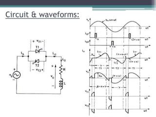
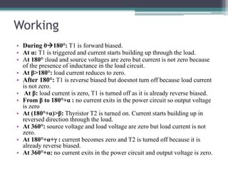
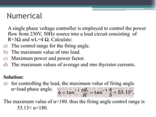
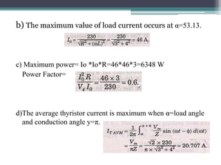
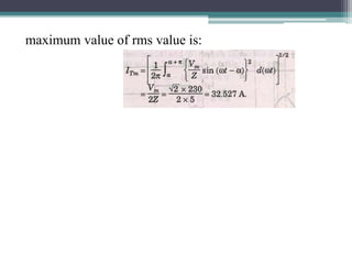

This document summarizes the operation of a single phase AC voltage controller with an RL load. It describes how the voltage is controlled using pairs of thyristors (SCRs) through phase control. During operation, the first thyristor T1 is triggered at firing angle α and conducts until 180°. The second thyristor T2 is then triggered at 180°+α and conducts until 360°+α, producing an output voltage that is variable but at the same frequency as the input supply. The document also provides an example calculation for controlling 230V, 50Hz power into a 3Ω resistor and 4Ω inductor load, determining the firing angle range, maximum load and power, power factor,


