Download as PDF, PPTX

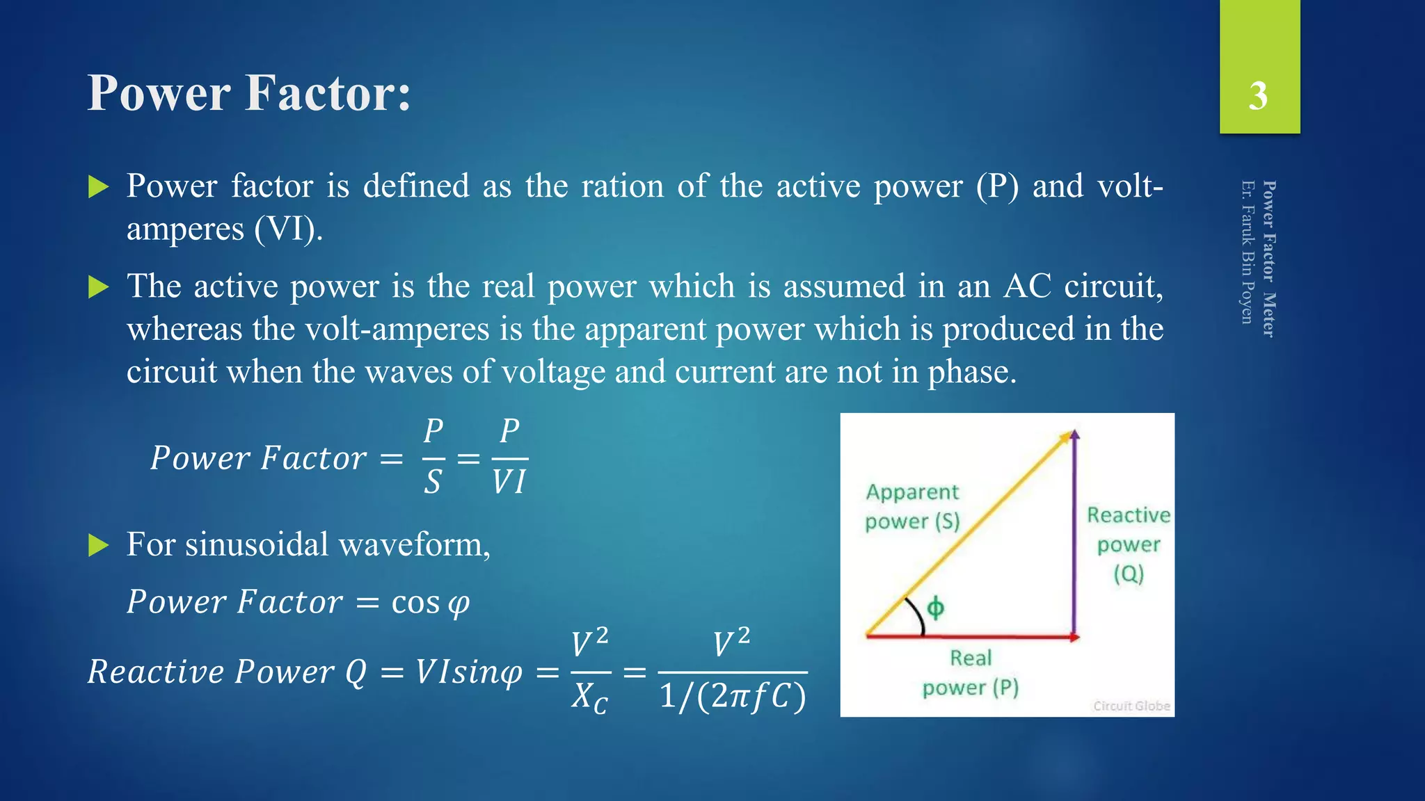


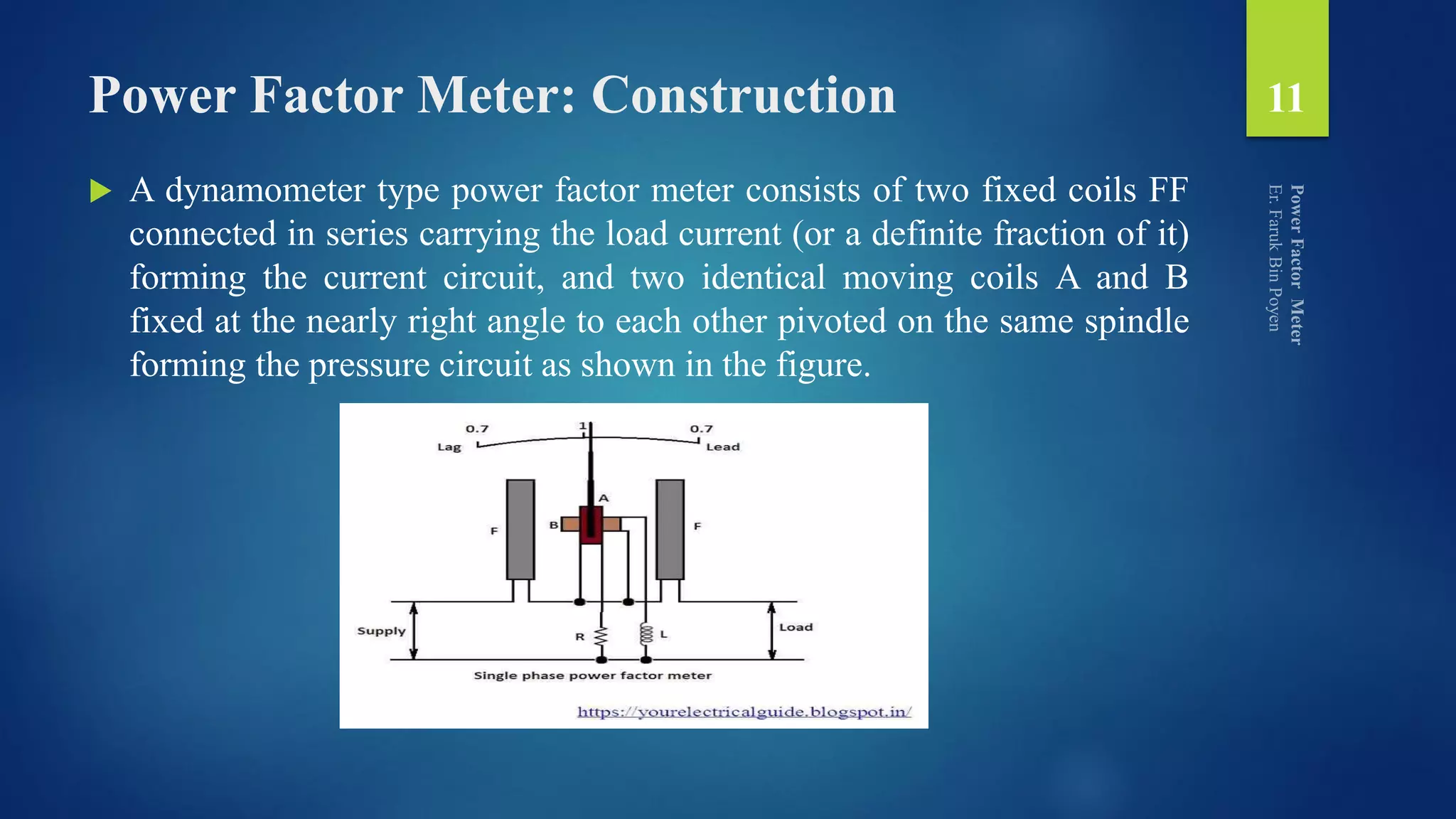


The document discusses power factor, its definition, causes of low power factor, and methods for improvement, including the use of capacitor banks, synchronous condensers, and phase advancers. It elaborates on how a power factor meter measures power factor in transmission systems, detailing its construction, working principle, and different output conditions for varying power factors. Additionally, it categorizes power factor meters into electrodynamometer and moving iron types.