This presentation explains the basics of rectifiers, including their types, working principles, and applications in electronic circuits. Ideal for students in electronics.
RECTIFIERS
This presentation providesa comprehensive overview of rectifiers,
essential components in power conversion that transform alternating
current (AC) into direct current (DC). We will begin with an introduction
to rectification principles, followed by a detailed exploration of different
rectifier types, including half-wave and full-wave rectifiers. We will
analyze the operation and circuit diagrams of each, culminating in a
comparison of their respective characteristics and applications. The
presentation will cover key concepts such as output DC voltage
calculation and efficiency considerations for each rectifier type.
3.
Overview of Rectifiers
1Introduction
Rectifiers are electrical devices that convert alternating current (AC) to direct current (DC). This process,
known as rectification, is fundamental in power electronics and electrical engineering.
2 Types of Rectifiers
There are three main types of rectifiers: half-wave rectifiers, full-wave rectifiers, and bridge rectifiers. Each
type has its own characteristics and applications in various electronic circuits.
3 Output Waveforms
The output waveforms of rectifiers vary depending on the type. Understanding these waveforms is crucial for
analyzing rectifier performance and designing power supply systems.
4.
Introduction to Rectification
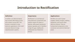
Definition
Arectifier is an electrical device
that converts alternating current
(AC) to direct current (DC). This
process is essential in many
electronic applications, from small
consumer devices to large
industrial power systems.
Importance
Rectification is crucial because
many electronic components and
systems require DC power to
operate, while power distribution
systems typically use AC. Rectifiers
bridge this gap, enabling the
widespread use of electronic
devices.
Applications
Rectifiers are used in power
supplies, battery chargers, welding
equipment, and various other
electronic devices. They are
fundamental components in the
conversion and control of electrical
power.
5.
Types of Rectifiers
Half-waveRectifier
A simple rectifier design that utilizes only one diode and conducts current during only half of the AC input waveform. This results in a
pulsating DC output with significant ripple and lower efficiency compared to full-wave rectifiers. It is primarily used in low-power applications
where cost and simplicity are prioritized over efficiency.
Full-wave Rectifier
A more efficient rectifier design that utilizes both halves of the AC input waveform to produce a DC output. This is typically achieved using
two diodes and a center-tapped transformer or a bridge rectifier configuration with four diodes. Full-wave rectifiers provide a smoother DC
output with less ripple than half-wave rectifiers, leading to improved efficiency and better performance for many electronic applications.
Bridge Rectifier
A common full-wave rectifier configuration using four diodes arranged in a bridge topology. This design eliminates the need for a center-
tapped transformer, reducing cost and size. Bridge rectifiers offer the advantages of full-wave rectification—higher efficiency and a smoother
DC output—while maintaining relative simplicity and being cost-effective. The output voltage is approximately the peak AC voltage minus
two diode voltage drops.
6.
Half-wave Rectifier
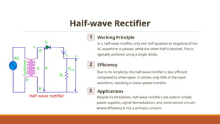
1 WorkingPrinciple
In a half-wave rectifier, only one half (positive or negative) of the
AC waveform is passed, while the other half is blocked. This is
typically achieved using a single diode.
2 Efficiency
Due to its simplicity, the half-wave rectifier is less efficient
compared to other types. It utilizes only 50% of the input
waveform, resulting in lower power transfer.
3 Applications
Despite its limitations, half-wave rectifiers are used in simple
power supplies, signal demodulation, and some sensor circuits
where efficiency is not a primary concern.
7.
Half-wave Rectifier Circuit
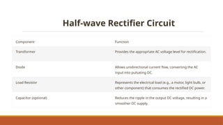
ComponentFunction
Transformer Provides the appropriate AC voltage level for rectification.
Diode Allows unidirectional current flow, converting the AC
input into pulsating DC.
Load Resistor Represents the electrical load (e.g., a motor, light bulb, or
other component) that consumes the rectified DC power.
Capacitor (optional) Reduces the ripple in the output DC voltage, resulting in a
smoother DC supply.
8.
Half-wave Rectifier Operation
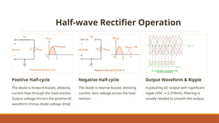
PositiveHalf-cycle
The diode is forward-biased, allowing
current flow through the load resistor.
Output voltage mirrors the positive AC
waveform (minus diode voltage drop).
Negative Half-cycle
The diode is reverse-biased, blocking
current; zero voltage across the load
resistor.
Output Waveform & Ripple
A pulsating DC output with significant
ripple (VDC 0.318Vm). Filtering is
≈
usually needed to smooth the output.
9.
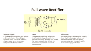
Full-wave Rectifier
Working Principle
Afull-wave rectifier converts both positive
and negative halves of the AC input
waveform to DC. This results in a more
efficient power conversion process
compared to half-wave rectifiers.
Types
There are two main types of full-wave
rectifiers: center-tapped transformer
rectifiers and bridge rectifiers. Both achieve
full-wave rectification but differ in their
component requirements and circuit
configurations.
Advantages
Full-wave rectifiers provide higher efficiency,
lower ripple in the output voltage, and
better transformer utilization. These
characteristics make them preferred for
many power supply applications.
10.
Comparison of RectifierTypes
Characteristic Half-wave Full-wave (Center-Tapped) Full-wave (Bridge)
Efficiency Low (40.6%) ~81.2% ~81.2%+
Output Ripple High (1.21 ripple factor) Moderate (0.48 ripple factor) Low (0.48 ripple factor)
Transformer Utilization Inefficient Good Excellent
Component Count Minimal (1 diode) Moderate (2 diodes, center-
tapped transformer)
Moderate (4 diodes)
Peak Inverse Voltage (PIV) 2Vm Vm Vm
Cost Lowest Moderate Moderate to High
Typical Applications Low-power applications Medium-power applications High-power applications
11.
Full Wave RectifierWorking Animation
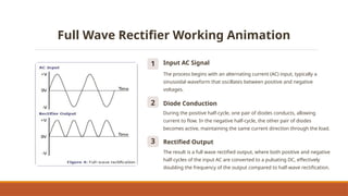
1 Input AC Signal
The process begins with an alternating current (AC) input, typically a
sinusoidal waveform that oscillates between positive and negative
voltages.
2 Diode Conduction
During the positive half-cycle, one pair of diodes conducts, allowing
current to flow. In the negative half-cycle, the other pair of diodes
becomes active, maintaining the same current direction through the load.
3 Rectified Output
The result is a full wave rectified output, where both positive and negative
half-cycles of the input AC are converted to a pulsating DC, effectively
doubling the frequency of the output compared to half-wave rectification.
12.
Output Waveforms
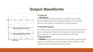
InputAC
Waveform
The top waveform displays the typical sinusoidal AC input voltage,
alternating between positive and negative polarities. This originates
from the mains supply or a transformer's secondary winding.
Rectified Output
The middle waveform shows the full-wave rectified output. Note that both
positive and negative half-cycles of the input are converted into positive
pulses, resulting in a ripple frequency double that of the input.
Smoothed DC
Output
The bottom waveform demonstrates the DC output after smoothing with a
capacitor. This significantly reduces the ripple voltage, providing a more
stable and usable DC voltage for electronic circuits.
13.
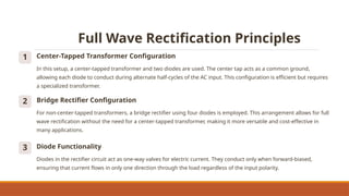
Full Wave RectificationPrinciples
1 Center-Tapped Transformer Configuration
In this setup, a center-tapped transformer and two diodes are used. The center tap acts as a common ground,
allowing each diode to conduct during alternate half-cycles of the AC input. This configuration is efficient but requires
a specialized transformer.
2 Bridge Rectifier Configuration
For non-center-tapped transformers, a bridge rectifier using four diodes is employed. This arrangement allows for full
wave rectification without the need for a center-tapped transformer, making it more versatile and cost-effective in
many applications.
3 Diode Functionality
Diodes in the rectifier circuit act as one-way valves for electric current. They conduct only when forward-biased,
ensuring that current flows in only one direction through the load regardless of the input polarity.
14.
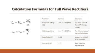
Calculation Formulas forFull Wave Rectifiers
Parameter Formula Description
Average DC Voltage
(Vdc)
2Vm / π 0.637Vm
≈ The mean value of
the rectified output
voltage
RMS Voltage (Vrms) Vm / 2 0.707Vm
√ ≈ The effective value of
the rectified voltage
Ripple Factor (RF) 0.482 Measure of residual
AC in the output
Form Factor (FF) 1.11 Ratio of RMS to
average value
15.
Bridge Rectifier: TheVersatile Full Wave
Solution
1 Diode Arrangement
Four diodes are arranged in a diamond configuration, creating two parallel paths
for current flow that alternate with each AC input half-cycle.
2 Current Flow
During positive half-cycles, diodes D1 and D2 conduct. During negative half-cycles,
D3 and D4 conduct, ensuring a consistently unidirectional current through the load.
3 Output Characteristics
This design delivers a full-wave rectified output without needing a center-tapped
transformer, resulting in enhanced efficiency and design flexibility.
4 Applications
The robustness and simplicity of bridge rectifiers make them ideal for diverse
applications, including electronic device power supplies, battery chargers, and
industrial power conversion systems.
16.
Positive and NegativeHalf Cycles in Bridge
Rectifiers
Positive Half Cycle
Diodes D1 and D2 conduct during the positive half-cycle. Current
flows from the positive terminal, through D1, the load, D2, and
back to the transformer's negative terminal.
Negative Half Cycle
During the negative half-cycle, D3 and D4 conduct. Current flows
from the now-positive lower terminal, through D3, the load, D4,
and back to the transformer's upper terminal.
17.
Conclusion: The Powerof Full Wave Rectification
Enhanced Efficiency
Full-wave rectifiers surpass half-wave rectifiers by utilizing both AC cycles, resulting in significantly improved efficiency and reduced ripple voltage.
Wide-ranging Applications
From compact consumer electronics to robust industrial systems, full-wave rectifiers are indispensable in modern power electronics, providing the
stable DC power essential for countless devices and applications.
Design Adaptability
Center-tapped and bridge configurations offer design flexibility, allowing engineers to optimize rectifier choice based on application demands, cost
factors, and performance targets.
Continuous Innovation
As power electronics advance, full-wave rectifiers will remain central, with ongoing research dedicated to enhancing efficiency, miniaturization, and
seamless integration with sophisticated power management systems.