Downloaded 1,229 times
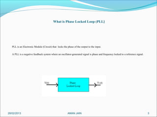
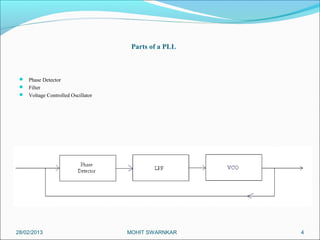
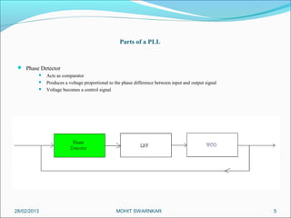
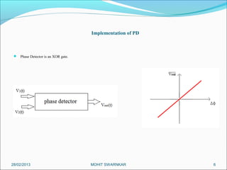
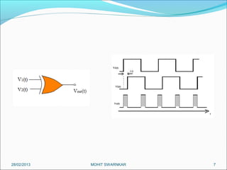
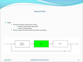
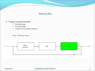
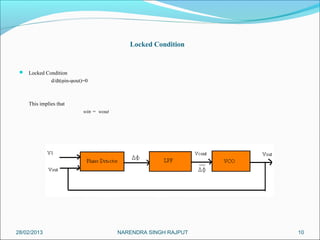
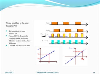
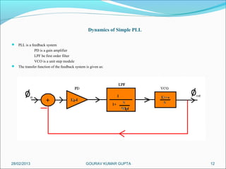
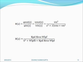
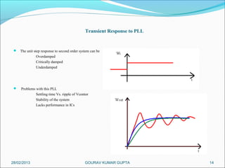
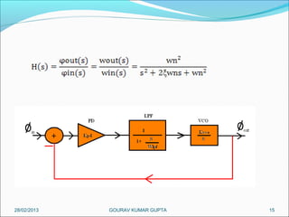
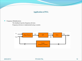
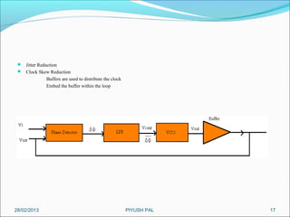


This presentation summarizes the key aspects of a Phase Locked Loop (PLL) circuit. It was presented by Aman Jain, Gourav Gupta, Mohit Swarnkar, Narendra Singh Rajput, and Piyush Pal to Ravitesh Mishra. The presentation outlines what a PLL is, the main components of a PLL including the phase detector, filter, and voltage controlled oscillator. It also discusses the locked condition of a PLL, the dynamics and transient response of PLL circuits, and applications of PLLs such as frequency multiplication, jitter reduction, and clock recovery.